Electron HS 12/24-30 Operating instructions
- Type
- Operating instructions

Part-No. 323 996 (Englisch) 01/09
Operating Instructions GB
Battery Charger
HS 12/24-30
Charger for 12 V and 24 V lead-acid batteries,
charging current up to 30 A
ELEKTRON-BREMEN GmbH Am Hohentorshafen 17-19 D-28197 Bremen Phone: +49/421/54906906 ·Fax: 5490619

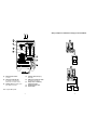
(1) Voltage selector switch (4) Charging cable, red clip (+),
(0 = OFF) black clip (-)
(2) Charging current indicator (5) Battery type changeover switch
the charging current flowing is (at bottom of the charger)
indicated (IN = nominal current) (6) Backup mode normal duty /
(3) Floating charge, illuminates green changeover switch
when battery is charged (7) Indication backup mode
(8) Fault indicator
LED = light-emitting diode
- 1 -
- 6 -
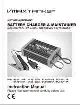
Wiring examples for simultaneous charging of several batteries

Fault indicator (8) illuminates with
steady light:
There is a system fault in the charger.
Switch off the charger - switch (1) in
position „0“ - and contact the
authorized workshop or your expert
dealer.
5.0 Technical data
Mains voltage 230 V
Mains frequency 50/60 Hz
Nominal voltage
12 V and 24 V
lead-acid
batteries
Constant voltage 2.4 / 2.35 V/cel
Charging current 30 A and 15 A
Charging characteristic
IUoU
Protection type IP 21
Metal housing
(W x H x D in mm) 135 x 260 x 275
Weight 5,2 kg
Length of charging
cable (incl. clips)
2 m
Length of mains cable 1.5 m
Subject to technical changes without prior
notice
The HS 12/24-30 Battery Charger
complies with the requirements of the
automotive industry and in particular
fulfils DIN EN 60335-2-29 and IEC 801.
- 5 -
Contents
1.0 Safety notes
2.0 Description of the unit
3.0 Startup
3.1 Charging
3.2 Backup mode
3.3 Floating mode/trickle charge
4.0 Fault indication and
troubleshooting
5.0 Technical data
1.0 Safety notes
Caution! Explosive gases are
generated during charging of
batteries!
Only charge batteries in well
ventilated areas. Explosion hazard
on account of generation of
oxyhydrogen gas!
Avoid all forms of fire, naked light
and sparking!
Wear protective goggles!
If acid splashes on to skin or
clothing, wash off immediately
with generous quantities of water!
Caution!
If there is a pungent smell of gas,
acute explosion hazard is present!
Do not switch the charger off!
Do not remove the charging clips!
Thoroughly ventilate the area
immediately!
After adequate ventilation, switch
the charger off!
Check the battery!
Protect the charger from damp and
wet!
Install the charger such that the air
outlet is free!
Ensure stable location of the
charger!
- 2 -
Electrical safety:
Mains and charging cable must be in perfect
condition. If these cables are damaged in
any way, contact the authorized workshop or
your expert dealer.
Before start-up of the unit read the
operating instructions carefully.
Always operate the charger according to
these instructions.
2.0 Description of the unit
With the battery charger HS 12/24-30 (in the
following „HS“) all 12- and 24V wet batteries
(also lead calcium), maintenance-free gel
batteries, fleece batteries and
AGM-batteries can be charged.
The required voltage can be selected with the
„charging voltage switch“ (1).
The unit is switched on, the lower yellow
LED (0%) flashes:
Either there is no battery connected or there is
no contact with the battery.
With changeover switch (5) you choose the
battery type:
2.4 V/cell for wet batteries / AGM-batteries
2.35 V/cell for gel batteries
The microprocessor of the HS controls the
charging current according to the discharge
degree of the battery and automatically
provides optimum charging.
Working on the open
unit may only be done
by an authorized and
skilled expert!

Charging current indicator
The present charging current is being
indicated by 5 LED’s.
At the start of the charging process all
5 LED’s illuminate. With proceeding
charging the charging current will decrease
and the LED’s will extinguish from the top to
the bottom one.
When only the last LED (IN = 0%) is still
illuminated, the battery is charged.
When in addition the green LED (3) =
floating charge is on, the HS has switched
over to floating operation.
Maximum charging current:
For 12 V: IN = 30 A
For 24 V: IN = 15 A
For being charged the battery can
stay in the vehicle and does not
have to be disconnected from the
vehicle electrical system.
Absolute protection of the on-board
electronic system, as no current
and voltage peaks occur.
Backup mode
The HS replaces the vehicle battery in case
it has to be changed. The on-board voltage
will be maintained.
Floating mode
In the floating mode the HS ensures
optimum charging and floating charging of
the battery.
Wrong polarity protection
The HS detects wrong polarity connection
and will not commence the charging
process.
Release of clips
The HS surely detects, when clips become
detached from the battery during the
charging process.
- 3 -
Exhausted batteries
The HS also detects exhausted batteries
and will commence the charging process
carefully.
The HS will adjust the charging current
automatically.
3.0 Start-up
Observe the precautions in the
safety notes!
Observe the handling instructions
of the battery manufacturer!
Determine the battery type.
Set the battery type with
changeover switch (5):
2.35 V/cell for gel batteries
2.4 V/cell for standard batteries /
AGM-batteries
3.1 Charging
Attention: Check the correct position of
the switch S1 12V-0-24V when setting
the charge voltage.
Connect charging clips to battery
terminals with correct polarity. Red
clip (+) to the positive terminal,
black clip (-) to the negative
terminal!
Set charging voltage with switch (1).
Charging indicators (2) illuminate.
When only the last LED (0%) is still
illuminated, the battery is charged.
Switch off the HS with switch (1).
Detach the clips from battery
terminals.
Charging exhausted batteries
The HS detects exhausted batteries.
The HS will commence the charging
process carefully with low charging
current and will subsequently adjust
the charging current to the battery
condition.
Battery voltage has to be at least 0,6 V.
3.2 Backup mode
Set battery type with changeover
switch (5).
Set backup mode with changeover
switch (6).
Connect charging clips to battery
terminals with correct polarity.
Red clip (+) to the positive
terminal, black clip (-) to the
negative terminal!
Caution!
During battery change the
charging clips must not come
loose from the battery terminals.
Select required voltage with
switch (1). The yellow LED (7) will
illuminate.
During backup mode the current is
limited to 5 A.
A minimum load current of 0.6 A
must flow, e. g. the parking light of
the vehicle must be switched on.
Otherwise backup charging is not
possible.
With changeover switch (6) set back
the HS to „normal operation“.
3.3 Floating mode/trickle charge
Connect charging clips to battery
terminals with correct polarity.
Red clip (+) to the positive
terminal, black clip (-) to the
negative terminal!
Select required voltage with
switch (1).
- 4 -
Charging indicators (2) illuminate.
When only the last LED (0%) is still
illuminated, the battery is charged.
If in addition the green LED (3) = floating
charge illuminates, the HS has switched
over to floating mode.
If the battery is being discharged by a
consumer during floating operation, the
HS automatically provides suitable
charging.
Floating mode can be carried out during
an unlimited period of time.
Observe the maintenance instructions
of the battery manufacturer.
Fault indicator (8) flashes:
- If temperature in the charger is too high
Is the air outlet at the rear panel of the
charger free?
Are the air intakes at the bottom of the
charger free?
After cooling down the HS automatically
continues the charging process.
- If charging clips have been connected
with wrong polarity
Connect the clips with correct polarity.
After elimination of the fault the fault
indicator (8) extinguishes.
- When battery voltage is too high
Determine voltage of the battery and set
accordingly with switch (1).
After correction of the voltage setting the
fault indicator (8) extinguishes.
- If battery is not correct or faulty
Check:
- the battery for defective cells
- the charging voltage which
has been chosen.
Connect new battery, switch
off the HS and subsequently
detach the charging clips.
4.0 Fault indication and troubleshooting
-
 1
1
-
 2
2
-
 3
3
-
 4
4


Electron HS 12/24-30 Operating instructions
- Type
- Operating instructions
Ask a question and I''ll find the answer in the document
Finding information in a document is now easier with AI
Other documents
-
Telair TBC3i PRO 30-20-250 Carica batterie triplo User manual
-
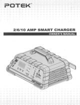 POTEK 2-6-10 Amp Smart Charger Owner's manual
-
 VDC Electronics BatteryMINDer 12248-AA-S1 User manual
-
RetroSound Exile EX-1 Battery Keeper Owner's manual
-
Century CC1206 Owner's manual
-
Sealey BSCU25 Operating instructions
-
-
TBB CF Series User manual
-
Medion AUTO XS MD 19787 User manual
-
 VMAXTANKS BC8S1212A User manual


