Form 51005 Rev. D
12-02-2002
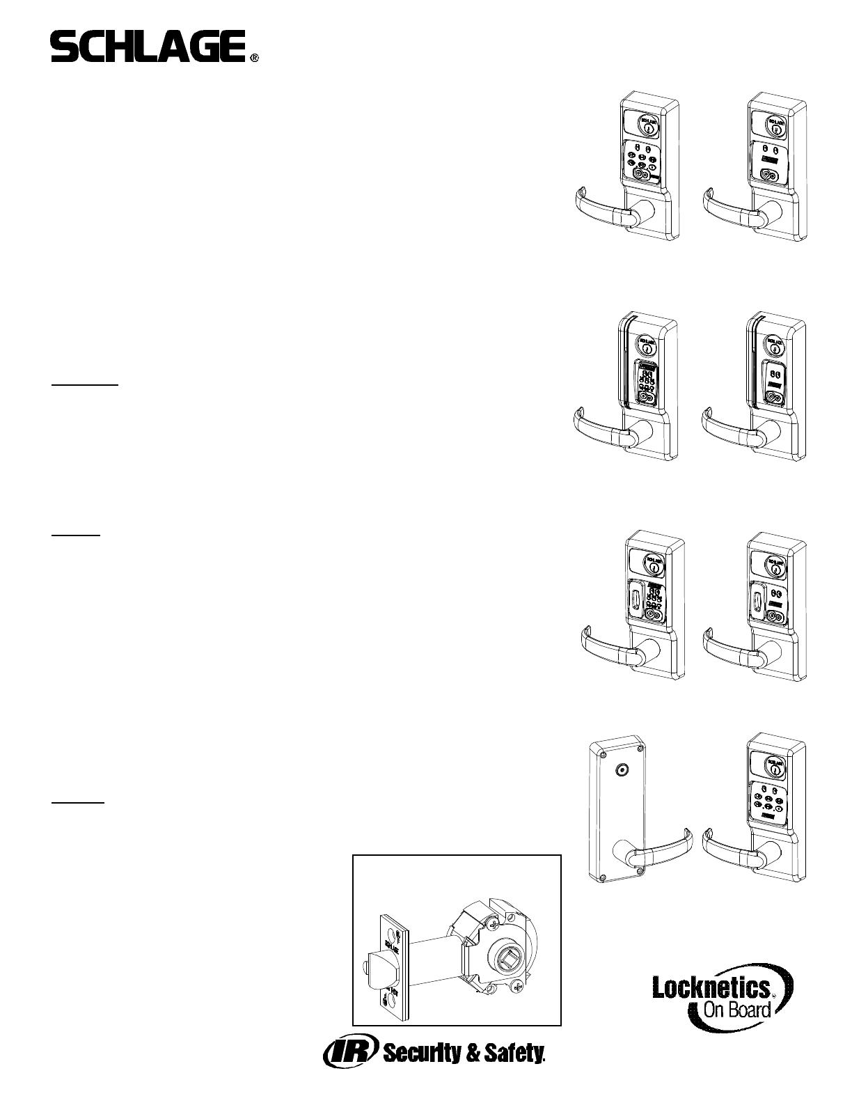
CM5100 COMPUTER MANAGED CYLINDRICAL LOCK
INSTALLATION MANUAL
CM5100-KPI CM5100-IBO
CM5100-MGK CM5100-MGI
PRO5100
The 5100 series lock is a stand-alone, microprocessor controlled, electromechani-
cal locking system. The 5100 employs a heavy-duty mechanical design with fewer
moving parts than a standard cylindrical lockset, for ease of installation and high
reliability. It is powered by four, standard AA batteries, providing up to 80,000 acti-
vations.
Operationally, the outside lever is normally locked and the inside lever is always
free to allow egress. Electronic access control is achieved by entering an ”Access
Credential” (magnetic stripe card, code, iButton Key, or Prox fob or card).
Electronic access control capabilities are listed below by model. All models are
designed to accommodate an emergency mechanical key override. Standard fea-
tures of the CM models include up to 1000 user memory, real time features includ-
ing time zones and holidays, and audit trail of up to 1000 events. Optional ATK
(audit trail - key override) will note any use of the mechanical key on the audit trail
report. Manual and computer programming is supported by all models. The PRO
models are manually programmed to accept up to 100 codes.
Functions
:
5190: Office Function - has “Lock” and “Unlock” buttons on inside escutcheon -
function not available on PRO
5196: Storeroom/Classroom Function - can be unlocked by “toggle” credential and
relocked again by same. See programming guide for more information.
5198: Classroom Function with inside iButton reader - can be toggled unlocked by
iButton plus pin (code). Can be relocked immediately from inside iButton reader in
an emergency.
Models
:
KPI: iButton reader and keypad
IBO: iButton reader only
MGK: Magnetic stripe card reader, iButton reader and keypad
MGI: Magnetic stripe card reader and iButton reader
PXK: HID Prox card reader, iButton reader, and keypad
PXI: HID Prox card reader and iButton reader
PPK: interflex ProxIF Prox card reader, iButton reader, and keypad
PPI: interflex ProxIF Prox card reader and iButton reader
PCK: Casi Rusco Prox card reader, iButton reader, and keypad
PCI: Casi Rusco Prox card reader and iButton reader
PRO: Keypad only - no computer programming, 100 code memory
Options:
ATK: Audit trail of mechanical key use (not available on PRO)
HSS: High security screws on inside escutcheon
SLB: 2-3/4” backset, 1/2” latch bolt
OLB: 2-3/8” backset, 1/2” latch bolt
ELB: 2-3/4” backset, 3/4” latch bolt
T3: Track 3 card reader (data on track 3
must be ABA track 2 format) - MGI/MGK only
KD: Keyed Different, includes Schlage
Everest cylinder
LC: Less Cylinder
5100 CYLINDRICAL
LOCKSET - STANDARD
CM5198
SAFE SCHOOL LOCK
WITH iBUTTON
READER ON INSIDE
CM5100-PXK
CM5100-PPK
CM5100-PCK
CM5100-PXI
CM5100-PPI
CM5100-PCI


