
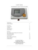
Differential Controller Solar Installations
Two or Three Sensors
Manual (02VDCS3-2013) GB
V-DCS3
www.vageo.gr
Thank you for buying this device.
Please read carefully the instructions to help you get all the bene-
fits of this device.
Page 2 Safety - Installation Specifications
Page 3.4 Applications & Links
Page 5 Operation - First Boot Screen
Page 6 Symbolisms Screen
Page 7 Operation
Page 8 Menu Setting Description Parameters
Page 9 Diagnostic Fault - Sensors
accessories

2
Safety instructions:
! Note: The placement of the device should be done by a licensed electrician journeyman
burners .
! Caution : This device is designed for installations electricity 230Volts AC/50Hz. Make
sure the power supply is interrupted before connecting the device and when for any rea-
son remove the plastic front cover and is mounted on the wall or in a box rail .
! Caution : This product should not be used in critical applications for human life. If the
product does not work as directed by the manufacturer consult the service department of
the manufacturing company (0030 210 2323345 ) .
Installing Installation:
The V-DCS3 device is enclosed in a box DIN RAIL BOX 6 fuses and can be mounted on
top hat rail box, table rail (see page 9) or directly on the wall.
The space that the device is positioned V-DCS3 should not wetted or not has a high mois-
ture level .
External cables connecting the power supply and signal cables is not necessary to cross to
exceed 1mm 2x1mm.
The cables connect the sensors of the device is not necessary that the cross-section not
exceed 0,50 mm 2x0, 50mm.
! Caution : The sensor cables should not be combined with power cords power and the
maximum length of these should not exceed 50m.
It is not necessary to open the device as you may create irreparable damage to electronic
circuits. The connection terminals are accessible immediately.
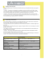
Specifications
Area Imaging Sensors & Setup Con-
trollers
-10,0 ⁰ C till +150,0 ⁰ C with a pitch 1 ⁰ C
Setting Precision Sensors Adjustable -3,0 ⁰ C to +3,0 ⁰ C with a pitch 1 ⁰ C.
dimensions
Power Supply ~ 230V AC/50Hz ± 10%
Resistance relay contacts 6A / 250 VAC
remote sensors Extension to 50 meters (V-KTYxxx)
temperature Operation -10,0 ⁰ C to +50,0 ⁰ C

3
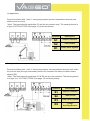
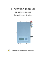
1st application:
Forced circulation with 1 sink, 1 solar pump system and two temperature sensors (one
collector and one sink).
! Note: The terminals with symbolism R1 are the dry contact relay. The sensing device is
of type V-KTY50 KTY200 (See page 10) and have polarity.
2nd application:
Forced circulation with 1 sink, 1 solar pump system, two temperature sensors (one collec-
tor and one sink) through a secondary source for domestic hot water circulator means
second (R2).
! Note: The terminals with symbolism R1 & R2 are dry relay contacts. The sensing device
is of type V-or V-KTY50 KTY200 (See page 10) and have polarity.
Symbols Description
S1
Sensor Collector
S2
Tank sensor
R1
Pump Solar System
Symbols Description
S1
Sensor Collector
S2
Tank sensor
R1
Pump Solar System
R2
Pump
Auxiliary Source

4
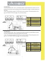
3rd Application:
Forced circulation with 1 sink, 1 solar pump system, three temperature sensors (one col-
lector & 2 sink) and control auxiliary source for domestic hot water circulator means sec-
ond (R2).
! Note: The terminals notation R1 & R2 are dry relay contacts. The sensing device of a
type V-KTY50 KTY200 (See page 10) and have polarity.
4th Application:
Forced circulation with 1 sink, 2 pumps solar collector system for each different orienta-
tion and 3 temperature sensors (two panels and one sink).
! Note: The terminals notation R1 & R2 are dry relay contacts. The sensing device of a
type V-or V-KTY50 KTY200 (See page 10) and have polarity.
Symbols
Description
S1
Sensor Collector
S2
Lower Tank Sensor
S3
Over Tank Sensor
R1
Solar Pump System
R2
Auxiliary Pump Source
Symbols
Description
S1
Sensor Collector No1
S2
Tank Sensor
S3
Collector Sensor no2
R1
Solar Pump System No1
R2
Solar Pump System No2

5
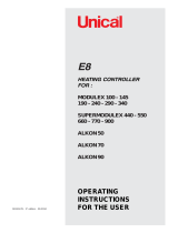
With the key you can browse the main setup menu (See page 8), and to reduce the val-
ues for each parameter we choose to modify. The button with the symbol functions as ON
-OFF to use the no auxiliary source applications 2 and 3 (see page 3 & 4), while in the main
menu setting as options to amend the parameter value as a ENTER fee and the modified pa-
rameter value.
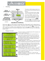
The device V-DCS3 adjusted with 3 but-
tons on the left of the screen as shown in
Figure 1.
The device once placed under voltage
works according to the factory settings
(see page 8 TABLE 1) shown in the
menu. To see these settings or modify
them to press simultaneously for 3sec
and 2 buttons with symbols
With the key you can browse the
main menu setting or increase the values
for each parameter we choose to modify.
Handling:
Display first start:
The device features a V-DCS3 backlit LCD 8 characters x 2
lines on a green background .
Connecting the power supply device is going through a
phase where starting and shown the first two screens se-
quentially as shown in Figure 2 . After booting the device
has started working normally reflecting successively 3,4,5
and 6 display continuously and repeatedly while making
temperature and other controls .
Screen 3: Message << SYS: number >> abbreviation of the
word SYSTEM is the first and basic parameter in the setup
menu to select the application you want to control our de-
vice ( see page 3 & 4) . Message << AUX: ON, OFF or NA
>> abbreviation AUXILIARY and reports the status of
OPEN , CLOSED or NO auxiliary source of DHW .
Screen 4 & 5: Message on screen 4 << S1: ° C >>, << S2: °
C >> and screen 5 << S3: NA >>, << S4: NA >> refers to
values of Celsius sensors at that time and detected accord-
ing to the application that we have chosen . The sensor S4
model V-DCS3 not applicable .
Screen 6 : Message << R1 R2 R3 >> shows the relay
status as controlled by our device at that time . The relay R3
model V-DCS3 not applicable .
FIGURE1
FIGURE 2

6
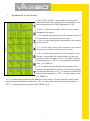
Symbolisms on the Screen:
FIGURE 3
<< AUX: OFF or ON >> as example on the screen 1,
shows the state of the controller checks whether or not
the auxiliary source for DHW applications 2 & 3.
<< Error >> like the example on the screen 2 means
damage to the sensor.
<< 0 >> below relay symbol as in the example screen 3
shows that the contact exists and is open.
<< NA >> under relay symbol indicates that the contact
does not exist.
<< 1 >> under relay symbol like the example on the screen 4
shows that the contact exists and that it is closed.
<< M >> below relay symbol as in the example on the
screen 5, shows that the contact exists, but the tem-
perature sensor collectors << S1 >> is below the value
of the parameter << MCT >> low temperature collector
(See . p.8 TABLE 1).
<< F >> under relay symbol like the example on the
screen 6 shows that the contact exists but the tempera-
ture sensor collectors << S1 >> is equal to or below the
value of the parameter << FPC >> frost protection (see
p.8 TABLE 1).
<< T >> under relay symbol like the example on the screen 7 shows that the contact exists
but the temperature sensor collectors << S1 >> has reached the value of the parameter <<
MTC >> overheat protection panel (See TABLE 1 p.8).

7
Cases Activation R2
* Abbreviations are explained in Table 1 ( see p.8 ) .
Enabling first implemented 2 when S2 <MST-DAS.
Enabling a second application 3 when the S3 <MST-DAS.
! Caution : In applications 2 & 3 have control auxiliary source , the message << AUX >> should
be << ON >>.
3rd Enabling Implementation 4 when (S3-S2) ≥ DTS & S3 ≥ MCT when the elapsed time of the
delay parameter CPD.
4th Enabling Implementation 4 when S3 ≤ FPC frost protection panels. The process of opening
and closing operation of R2 is a time (120 sec) by repeating S3> FPC.
5th Enabling Implementation 4 when S3 ≥ MTC overheat protection panels. The R2 will be dis-
abled when S3 <MTC at 3 ° C or HST = MTC.
Operation:
The device V-DCS3 the time to be fed with electricity constantly performs checks proper func-
tioning sensory outputs and relay contacts are available . The green screen background after
10 sec disappears , comes back with the click of one of the three buttons .
Cases Trigger R1
* Abbreviations are explained in Table 1 ( see p.8 ) .
It is activated when the first (S1-S2) ≥ DTS & S1 ≥ MCT applies to all applications when the
elapsed time of the delay parameter CPD.
Enabling second when S1 ≤ FPC frost protection panels apply to all applications. The process
of opening and closing operation of R1 is a time (120 sec) by repeating S1> FPC.
Enabling third when S1 ≥ MTC overheat protection panels apply to all applications. The R1 will
be disabled when S1 <MTC at 3 ° C or HST = MTC.

8
Α/Α
Abbreviation
Description of Parameters
FROM TO
1
SYSTEM
Select Application ( See pages 3 & 4) .
1 4 1
2
HST
Higher Sink Temperature
Maximum desired temperature heat sink .
20°C 95°C 80°C
3
DTS
Differential Temperature Sensors
Differential temperature S1-S2 ( for all applications ) and
the S3-S2 ( only for application 4 ) which will trigger the
R1 ( for all applications ) and the R2 ( only for application
4 ) respectively.
ODT 30°C 8°C
4
ODT
Off Difference Temperature
Differential temperature S1-S2 ( for all applications ) and
the S3-S2 ( embodiment 4 only ) which will turn off the R1
( for all applications ) and the R2 ( only for application 4 )
respectively.
1°C DTS 3°C
5
CPD
Clock Pump Delay
Delay activate circulators collectors.
0 sec 240 sec 30 sec
6
MCT
Minimum Collector Temperature
Low temperature collectors for which actuated pumps col-
lectors.
10°C 80°C 10°C
7
MTC
Maximum Temperature Collector
Overheat protection panels.
100°C 150°C 110°C
8
FPC
Frost Protection for Collector
Frost protection panels.
-10°C 5°C 3°C
9
MST
Minimum Sink Temperature
Minimum temperature in the DHW storage tank (only ap-
plications 2 and 3 ) .
20°C 80°C 35°C
10
DAS
Differential Auxiliary source
Different minimum temperature in DHW storage tank
(only applications 2 and 3 )
10°C 3°C 5°C
11
EXIT
Exit from Menu
Setup Menu: TABLE 1
default

9
Fault diagnosis:
The device V-DCS3 the time to be fed with electricity, check the status of the sensors continu-
ously. If any of the sensors has a problem or the cable is then cut on the screen shows the mes-
sage << Error >> next to the corresponding sensor (See page 6 example display 2).
CAUTION: For safety reasons, if a fault is detected in the collector sensor or sensors collectors
(application 4), the relay or relays (application 4) circulators will be activated and the relay R2
applications 2 and 3 will be disabled.
Sensors & Accessories:
Immersion Sensor (+180 ° C) V-KTY 50 with 50cm cable length and
diameter cup 6mm. The type of cable is 2x0, 50mm silicone.
Immersion Sensor (+180 ° C) V-KTY200 with cable length 2 m and di-
ameter cup 6mm. The type of cable is 2x0, 50mm silicone.
The VAGEO HVAC products designed and manufactured in Greece
by INTELCO Electronics PELEKIS E. & Co.
Christos Karvouni 27 Ta.K.136 71 Axarnai Attica
T.+30 2102323345 F.+30 2102386382
vageo@intelco.gr www.intelco.gr - www.vageo.gr
-
 1
1
-
 2
2
-
 3
3
-
 4
4
-
 5
5
-
 6
6
-
 7
7
-
 8
8
-
 9
9


Ask a question and I''ll find the answer in the document
Finding information in a document is now easier with AI
Other documents
-
 Thermo Products USDT2004 User manual
-
Alpha innotec EP Owner's manual
-
Alpha innotec Comfort-Platine II Owner's manual
-
DOMUSA TEKNIK DS-matic 1.15 Duo Installation And Operating Instructions Manual
-
Baxi POWER HT+ 1.90 Installation and Service Manual
-
 ZilanSolar SR981S Operating instructions
-
Buderus Logamatic 2107 Installation And Service Instructions Manual
-
-
STIEBEL ELTRON SOM 8 plus Installation guide
-
 Unical ALKON 50 C Owner's manual


