Sunny Health & Fitness SF-RW5727 User manual
- Type
- User manual

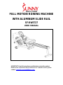
FULL MOTION ROWING MACHINE
WITH ALUMINUM SLIDE RAIL
SF-RW5727
USER MANUAL
IMPORTANT! Read all instructions carefully before using this product.
Retain owner’s manual for future reference. For customer service, please
contact: [email protected]

1
IMPORTANT SAFETY INFORMATION
We thank you for choosing our product. To ensure your safety and health, please use this
equipment correctly. It is important to read this entire manual before assembling and using the
equipment. Safe and effective use can only be achieved if the equipment is assembled, maintained
and used properly. It is your responsibility to ensure that all users of the equipment are informed of
all warnings and precautions.
1. Before starting any exercise program you should consult your physician to determine if you have
any medical or physical conditions that could put your health and safety at risk, or prevent you
from using the equipment properly. Your physician’s advice is essential if you are taking
medication that affects your heart rate, blood pressure or cholesterol level.
2. Be aware of your body’s signals. Incorrect or excessive exercise can damage your health. Stop
exercising if you experience any of the following symptoms: pain, tightness in your chest,
irregular heartbeat, shortness of breath, lightheadedness, dizziness or feelings of nausea. If you
do experience any of these conditions, you should consult your physician before continuing with
your exercise program.
3. Keep children and pets away from the equipment. The equipment is designed for adult use only.
4. Use the equipment on a solid, flat level surface with a protective cover for your floor or carpet. To
ensure safety, the equipment should have at least 2 feet (60 CM) of free space all around it.
5. Ensure that all nuts and bolts are securely tightened before using the equipment. The safety of
the equipment can only be maintained if it is regularly examined for damage and/or wear and
tear.
6. Always use the equipment as indicated. If you find any defective components while assembling
or checking the equipment, or if you hear any unusual noises coming from the equipment during
exercise, discontinue use of the equipment immediately and do not use until the problem has
been rectified.
7. Wear suitable clothing while using the equipment. Avoid wearing loose clothing that may become
entangled in the equipment.
8. Do not place fingers or objects into the moving parts of the equipment
9. The maximum weight capacity of this unit is 300 pounds (135 KG).
10. The equipment is not suitable for therapeutic use.
11. Use caution when lifting and moving the equipment. Always use proper lifting technique and
seek assistance if necessary.
12. Your product is intended for use in cool, dry conditions. You should avoid storage in extreme cold,
hot or damp areas as this may lead to corrosion and other related problems.
13. This equipment is designed for indoor and home use only! It is not intended for commercial use!
WARNING: This product can expose you to one or more chemicals known to the State of
California to cause cancer and birth defects or reproductive harm. For more information go
to www.P65Warnings.ca.gov.

2
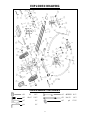
EXPLODED DRAWING
HARDWARE PACKAGE
#39 M8 2PCS #15 Φ10*60 2PCS
#43 M8*15 13PCS #53 M2*150 2PCS
#17 1PC #45 φ8 15PCS
#14 1PC

3
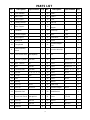
PARTS LIST
No.
Description
Specification
Qty
No.
Description
Specification
Qty
1
Front Stabilizer
1
28
Pedal L
1
2
Main Frame
1
29
Pedal R
1
3
Rear Support
1
30
Cover
1
4
Rotating Armrest
1
31
End Cap
1
5
Meter Support
1
32
Armrest Limit
Stopper
2
6
Handlebar
2
33
Foam Grip
L200
2
7
Handrail Support
1
34
Meter
L300
1
8
Seat Support
1
35
Trunk Wire F
L750
1
9
Sliding Rail
1
36
Sensor
1
10
Fixing Board
1
37
Induction Magnet
Seat
1
11
Rear Supporting
Board
1
38
Induction Wire Clip
1
12
Inner Sleeve Shaft
φ20*60(M10)
1
39
Nut
M8
8
13
Hydraulic Cylinder
φ42*300
1
40
Screw
M10*15 S
=
6
2
14
Allen Wrench
5#
1
41
Screw
M8*30 15 S
=
4
4
15
Bolt
φ10*60
2
42
Screw
M8*40 20 S
=
5
2
16
Foot Rest shaft
φ12*250
2
43
Screw
M8*15 S
=
5
19
17
Spanner
S=10、13、17、19
1
44
Screw
M6*15
4
18
Cir Clip
φ12
2
45
Washer
8
27
19
Seat
1
46
Screw
M5*12
2
20
Bearing
4
47
Washer
5
2
21
End Cap
30*70
2
48
Pedal Strap
2
22
End Cap
30*70*1.5
2
49
Induction Magnet
Φ15*3
1
23
Adjustable Pad
2
50
Tablet Bracket
1
24
Plastic Axle Sleeve
φ42*φ20*19
2
51
Screw
ST2.6*8
2
25
End Cap
φ28*2.0
2
52
Washer
10
2
26
End Cap
φ42*2.0
2
53
Bolt
φ12*150
2
27
Limit Mat
4

4
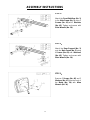
ASSEMBLY INSTRUCTIONS
STEP 1:
Attach the Front Stabilizer (No. 1)
to the Main Frame (No. 2) using 2
Screws (No. 43) and 2 Washers
(No. 45). Tighten and secure with
Allen Wrench (No. 14).
STEP 2:
Attach the Rear Support (No. 3)
onto the Main Frame (No. 2) using
4 Screws (No. 43) and 4 Washers
(No. 45). Tighten and secure with
Allen Wrench (No. 14).
STEP 3:
Remove 2 Screws (No. 46) and 2
Washers (No. 47) from the back of
the Meter (No. 34) with Allen
Wrench (No. 14).

5
STEP 4:
Insert the Meter (No. 34) into the
Meter Support (No. 5). Then
attach the Meter (No. 34) onto the
Meter Support (No. 5) using 2
Screws (No. 46) and 2 Washers
(No. 47). Tighten with Allen
Wrench (No. 14).
STEP 5:
Connect E with F. Attach the Meter
Support (No. 5) onto the Main
Frame (No. 2) using three Screws
(No. 43) and three Washers (No.
45). Tighten and secure with Allen
Wrench (No. 14).
STEP 6:
Insert the 2 Bolts (No. 53) into the
Main Frame (No. 2) with the
Spanner (No. 17). Then insert the
2 Foot Rest Shafts (No. 16)
through the Pedals L/R (No. 28 &
29) and fix into the Meter Support
(No. 5).

6
The assembly is complete!
STEP 7:
Attach the Handlebar (No. 6) into
the Rotating Arm Rest (No. 4)
using 2 Bolts (No. 15), 2 Washers
(No. 45) and 2 Nuts (No. 39).
Tighten and secure with Allen
Wrench (No. 14) and Spanner
(No. 17).
STEP 8:
Make sure the arrow on the Seat
(No. 19) points to the pedals.
Attach the Seat (No. 19) to the
Seat Support (No. 8) using 4
Screws (No. 43) and 4 Washers
(No. 45). Tighten and secure with
Allen Wrench (No. 14).

7
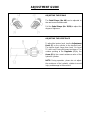
ADJUSTMENT GUIDE
ADJUSTING THE PEDALS
The Pedal Straps (No. 48) can be adjusted to
the user’s own foot/shoe size.
Pull the Pedal Straps (No. 28/29) to adjust the
degree of tightness.
ADJUSTING THE RESISTANCE
To adjust the tension level, turn the Adjustment
Knob (C) on the cylinder to the desired level.
The tension levels range from Level 1 to Level
12, with Level 1 being the lowest resistance. The
number pointing to the Regulator (C) by the
Arrow (B) is the current resistance value of the
hydraulic cylinder.
NOTE: During operation, please do not adjust
the resistance of the hydraulic cylinder to avoid
injury and damage to the machine.

8
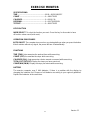
EXERCISE MONITOR
SPECIFICATIONS:
TIME--------------------------------------------------00:00—99:59 MIN/SEC
COUNT-----------------------------------------------0—9999 TIMES
CALORIES------------------------------------------0—999.9 CAL
REPS/MIN-------------------------------------------0—999 TIMES/MIN
TOT.CNT---------------------------------------------0—9999 TIMES
KEY FUNCTION
MODE/SELECT: To select the function you want. Press the key for 4seconds to have
all function values reset (total reset).
OPERATION PROCEDURES
AUTO ON/OFF: The computer turns on when you start pedaling or when you press the button.
After 4 minutes without any signal, the power will turn off automatically.
FUNCTIONS
TIME (TMR): Auto-memorize the workout time while exercising.
COUNT (CNT): Accumulate the steps while exercising.
CALORIES (CAL): Auto-memorize calories amount consumed while exercising.
TOTAL CNT (TOT.CNT): Display the steps you have exercised.
COUNT/MIN (CN/M): Display the steps per minute while exercising.
BATTERY
The exercise computer uses 2 AAA batteries. If there is a problem with the display try
changing the batteries first. Dispose of old batteries according to your regional guidelines.
Replace the batteries at the same time.
Version 1.1
-
 1
1
-
 2
2
-
 3
3
-
 4
4
-
 5
5
-
 6
6
-
 7
7
-
 8
8
-
 9
9


Sunny Health & Fitness SF-RW5727 User manual
- Type
- User manual
Ask a question and I''ll find the answer in the document
Finding information in a document is now easier with AI
Related papers
-
 Sunny Health & Fitness SF-RW5856 User guide
-
 Sunny Health & Fitness SF-BH6506 User manual
-
 Sunny Health & Fitness SF-B1423 User manual
-
 Sunny Health & Fitness SF-RW5515 User manual
-
 Sunny Health & Fitness SF-B1735 User guide
-
Sunny Health & Fitness SF-S0870 User guide
-
 Sunny Health & Fitness SF-B1002C User guide
-
 Sunny Health & Fitness SF-RB4806 User guide
-
 Sunny Health & Fitness ZEPHYR AIR BIKE User manual
-
 Sunny Health & Fitness NO. 077 Installation guide


Other documents
-
 SUNNY Health Fitness SF-S0978 Total Body Stepper Machine User manual
-
Patio Festival PF18223 Operating instructions
-
HomeSullivan 40E031-AMC2PCBU Operating instructions
-
 ARTIVA AF20203BG Installation guide
-
SereneLife SLRWMC10 Owner's manual
-
Kmart 42956990 User manual
-
ANGELES HOME CK70-OP424GR+ Operating instructions
-
Fitness Reality 2338Y Owner's manual
-
-

