Page is loading ...

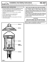
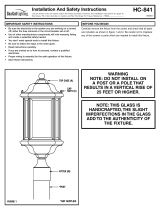
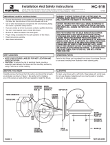
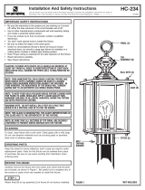
FINIAL (A)
FIGURE 1
*NOT INCLUDED
FITTER (E)
Installation And Safety Instructions
Line art shown may not exactly match the fixture enclosed. However, the installation instructions do apply to
this fixture. Fill in Item Number on Carton and File This Sheet For Future Reference. ITEM#_______________
HC-920
0
71508
• Be sure the electricity to the system you are working on is turned
off; either the fuse removed or the circuit breaker set at off.
• Use of other manufacturers components will void warranty, listing
and create a potential safety hazard.
• If you are unclear as to how to proceed, contact a qualified
electrician.
• You don’t need special tools to install this fixture.
•
Be sure to follow the steps in the order given.
• Proper wiring is essential for the safe operation of this fixture.
•
Fixtures with photocells should be mounted at least 48" from all
sides to avoid reflection of light back onto photocell, causing the
photocell to malfunction or flicker.
• Read instructions carefully.
• Save these instructions.
IMPORTANT SAFETY INSTRUCTIONS
NOTE: DO NOT INSTALL ON A POST OF A POLE THAT RESULTS IN A
VERTICAL RISE OF 25 FEET OR HIGHER.
NOTE: THIS GLASS IS HANDCRAFTED, THE SLIGHT IMPERFECTIONS IN
THE GLASS ADD TO THE AUTHENTICITY OF THE FIXTURE.
NOTE FOR FIXTURES THAT ARE SOLID BRASS OR SOLID COPPER:
YOUR HANDCRAFTED, SOLID BRASS/SOLID COPPER LIGHTING
FIXTURE HAS BEEN COATED WITH A DURABLE, BAKED ON ACRYLIC
LACQUER WHICH GIVES MAXIMUM PROTECTION AGAINST THE
WEATHER. IN TIME, HOWEVER, THE BRIGHTNESS OF THE BRASS WILL
TARNISH GIVING WAY TO AN AUTHENTIC OLD WORLD BRASS FINISH.
NOTE: TO KEEP YOUR SOLID POLISHED BRASS/COPPER FIXTURE
LOOKING NEW FOR YEARS TO COME, REGULARLY APPLY A GOOD
QUALITY NON-ABRASIVE CAR WAX TO ALL METAL SURFACES, GIVING
THE FIXTURE AN EXTRA PROTECTIVE COATING. IF THIS ADDITIONAL
CARE IS NOT TAKEN, YOUR FIXTURE WILL TURN INTO A PATINA
FINISH OVER TIME
To clean, wipe fixture with a soft cloth. Clean glass with a mild soap.
Do not use abrasive materials such as scouring pads or powders,
steel wool or abrasive paper
.
CLEANING
Keep this sheet for future r
eference, and in case you need to or
der
r
eplacement parts. Parts for this fixture can be ordered from place of
purchase. Be sure to use exact wording from illustration when
ordering parts.
ORDERING PARTS
Carefully remove the fixture from the carton and check that all parts
are included, as shown in figure 1. Be careful not to misplace
any of the screws or parts which are needed to install this fixture.
BEFORE YOU BEGIN
DECORATIVE
CUP (F)
ROOF
ASSEMBLY (E)
GLASS
(D)

IMPORTANT: DO NOT ATTACH FIXTURE DIRECTLY TO OUTLET BOX.
A. Take note of the color of the wire(s) on your fixture. Identify which
g
roup your fixture wire(s) falls into and connect the wires according
to the directions below:
*Note: When parallel wire is used, the tracer wire is square shaped or
ridged and less tracer wire is round in shape or smooth
(Seen best when viewed from wire end). To separate wires, grasp the
ends of each wire and pull apart.
B. Take your fixture wire(s) from group A and place evenly against
the black wire from the outlet box.
DO NOT twist wires together
before using wire connectors.
C. Fit a wire connector (not supplied) over the wires and thread the
connector clockwise until you feel a firm resistance.
D. Gently try to remove the wires from the connector, If you can
remove the wires, carefully re-do steps B and C, as above and check
again for a firm connection.
E. Connect the fixture wire from group B to the white wire from the
outlet box in the same manner
.
I
nstall self ballasted lamp (B) by twisting into socket (C) gently.
Make sure no bare wires can be seen outside wire connectors.
I
nstall glass (D) and roof assembly (E), decorative cup (F) over center
rod and secure with finial (A).
STEP 1:
INSTALLATION HC-920 FINAL ASSEMBLY
STEP 1:
STEP 2:
*PARALLEL WIRE (ROUND & SMOOTH) *PARALLEL WIRE (SQUARE & RIDGED)
BLACK WHITE
GROUP A:
CONNECT TO BLACK HOUSE WIRE
GROUP B:
CONNECT TO WHITE HOUSE WIRE
Hg
MARK MEANS LAMP CONT
AINS MERCUR
Y
.
FOLLOW DISPOSAL LAWS.
SEE WWW.LAMPRECYCLE.ORG
FIGURE 2
FIXTURES WITH A ONE PIECE
LAMP / BALLAST COMBINATION
LAMP (A)
SOCKET (F)
GROUNDING INSTRUCTIONS: Connect the ground wire from the
fixtur
e (bare metal or green insulated wire) to the ground wire from
the power supply (bare metal or green insulated wire) using a small
wire connector (not supplied).
NEVER CONNECT GROUND WIRE
TO BLACK OR WHITE POWER SUPPLY WIRES.
STEP 2:
Slide fitter (F) onto post. Secure in place with screws if applicable.
STEP 3:

FLEURON (A)
FIGURE 1
*PAS INCLUS
INSTALLATEUR (E)
Installation et consignes de sécurité
Line art illustré peut ne pas correspondre exactement l'appareil ci-joint. Toutefois, les instructions d'installation ne s'appliquent à
ce luminaire. Remplissez Numéro de l'article sur le carton et le fichier Cette fiche pour référence ultérieure. ARTICLE #_______________
HC-920
071508
• Assurez-vous de l'électricité au système sur lequel vous travaillez est activé
large; retirer le fusible ou disjoncteur mis en tension.
L'utilisation d'autres composants des fabricants annulera la garantie, la liste
et créer un risque de sécurité potentiel.
Si vous n'êtes pas sûr de savoir comment procéder, contactez un électricien
qualié.
Vous n'avez pas besoin d'outils spéciaux pour installer cet appareil.
Assurez-vous de suivre les étapes dans l'ordre donné.
Câblage adéquat est essentiel pour le bon fonctionnement de cet appareil.
Calendrier avec cellules photoélectriques doivent être montés à au moins
48 "de tous côtés pour éviter la réexion de la lumière en arrière sur la cellule
photoélectrique, provoquant la
cellule photoélectrique d'un dysfonctionnement ou de scintillement.
Lisez attentivement les instructions.
Conservez ces instructions.
•
•
CONSIGNES DE SÉCURITÉ IMPORTANTES
ATTENTION: NE PAS INSTALLER SUR UN POSTE D'UN POLE QUI SE
TRADUIT PAR UN DÉNIVELÉ DE 25 PIEDS OU PLUS.
ATTENTION: CE VERRE EST FABRIQUÉ À LA MAIN, LES LÉGÈRES
IMPERFECTIONS DANS LE VERRE AJOUTENT À L'AUTHENTICITÉ DE
L'APPAREIL.
ATTENTION: LES APPAREILS QUI SONT EN LAITON MASSIF OU EN
CUIVRE MASSIF: VOTRE ARTISANALE, LAITON MASSIF / SOLIDE
ÉCLAIRAGE DE CUIVRE APPAREIL A ÉTÉ REVÊTU D'UNE SOLUTION
DURABLE, CUIT SUR LAQUE ACRYLIQUE QUI OFFRE UNE
PROTECTION MAXIMALE CONTRE LES INTEMPÉRIES. AVEC LE
TEMPS, CEPENDANT, LA LUMINOSITÉ DE LAITON SE TERNIRA
CÉDER TI UNE VIEILLE FINITION AUTHENTIQUE EN LAITON DU
MONDE.
ATTENTION:POUR GARDER VOTRE APPAREIL LAITON POLI
SOLIDE / CUIVRE À LA RECHERCHE DE NOUVEAU POUR LES
ANNÉES À VENIR, APPLIQUER RÉGULIÈREMENT UNE CIRE NON
ABRASIVE DE VOITURE DE BONNE QUALITÉ SUR TOUTES LES
SURFACES MÉTALLIQUES, DONNANT LA FIXATION D'UN
REVÊTEMENT DE PROTECTION SUPPLÉMENTAIRE. SI CES SOINS
SUPPLÉMENTAIRES NE SONT PAS PRISES, VOTRE APPAREIL VA SE
TRANSFORMER EN UNE PATINE AU FIL DU TEMPS.
NETTOYAGE
COMMANDE DE PIÈCES
BEFORE YOU BEGIN
DECORATIVE
CUP (F)
ASSEMBLAGE
DE TOIT (E)
VERRE
(D)
•
•
•
•
•
•
Pour nettoyer, essuyez l 'appareil avec un chion doux. Nettoyez la
vitre avec un savon doux.
Ne pas utiliser de matériaux abrasifs tels que les tampons à récurer
ou de poudres, de laine d'acier ou de papier abrasif.
Gardez cette feuille pour référence future, et en cas yo besoin de
commander la pièce de remplacement. Pièces pour cet appareil
peuvent être commandés auprès du lieu d'achat. Assurez-vous
d'utiliser une formulation exacte de l'illustration quand
Retirez délicatement l'appareil du carton et vériez que
toutes les pièces sont incluses, comme le montre la gure
1 Veillez à ne pas égarer de vis ou des pièces qui sont
nécessaires pour installer cet appareil.

IMPORTANT: NE PAS FIXER APPAREIL DIRECTEMENT BOÎTE
DE SORTIE.
A.
B.
C.
D.
E.
Installer soi lampe ballast (b) en le tournant dans la prise (c) en douceur.
Assurez-vous qu'aucun fil dénudé ne dépasse des connecteurs.
ÉTAPE 1:
029-CHNOITALLATSNI FINAL ASSEMBLY
ÉTAPE 1:
ÉTAPE 2:
* FIL PARALLÈLE (ROND ET LISSE) * CÂBLE PARALLÈLE (CARRÉ ET STRIÉE)
GROUPE A:
CONNECTER AU FIL DE MAISON NOIRE
GROUPE B:
CONNECTER AU FIL BLANC DE LA MAISON
Hg
MARK MEANS LAMP CONT AINS MERCUR Y.
FOLLOW DISPOSAL LAWS.
SEE WWW.LAMPRECYCLE.ORG
FIGURE 2
AMPOULE (A)
DOUILLE (F)
ÉTAPE 2:
Faites glisser monteur (F) sur poste. Fixez en place avec les vis le cas échéant.
ÉTAPE 3:
Prenez note de la couleur du l (s) sur votre appareil. identier les votre
groupe l (s) de xation tombe dans et brancher les ls selon les
instructions ci-dessous:
NOIRE BLANC
* Remarque: Lorsque le l parallèle est utilisé, le l traceur est de forme carrée
ou l traceur striée et moins est de forme ronde ou lisse (Vu lorsqu'on la
visionne à partir de l'extrémité du l). Pour ls séparés, saisir les extrémités de
chaque l et séparer.
Prenez votre l (s) de xation du groupe A et placer uniformément sur le l
noir de la boîte de sortie. NE PAS tourner ls ensemble avant en utilisant les
connecteurs.
Monter un connecteur de câble (non fourni) sur les ls et visser le raccord vers
la droite jusqu'à ce que vous sentez une résistance ferme.
Essayez de retirer délicatement les ls du connecteur, Si vous pouvez enlever les
ls soigneusement refaire les étapes B et C, comme ci-dessus et vérier à nouveau
pour une connexion ferme.
Connectez le l de xation du groupe B au l blanc de la boîte de sortie de la
même manière
INSTRUCTIONS DE MISE À LA TERRE : Connectez le l de masse de
l'appareil (métal nu ou l isolé vert) pour le l de terre de l'alimentation
(métal nu ou l isolé vert) à l'aide d'un petit connecteur du câble
(non fourni). NE JAMAIS CONNECTER FIL DE TERRE AU NOIR OU BLANC
FILS D'ALIMENTATION.
LUMINAIRES AVEC UN COMBINAISON
D'UN BALLAST D'UNE
AMPOULE D’UNE PIÈCE
Installer du verre (D) et l'assemblage du toit (E), tasse décorative (F) sur la
tige de centre et le xer avec euron (A).
/
