Page is loading ...

MUSTANG 4000 SWITCH SERIES
DG-FS4510
INSTALLATION GUIDE
V1.0
2012-07-12
As our products undergo continuous development the specifications are subject to change without prior notice

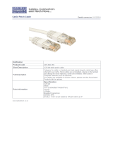
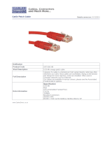
DG-FS4510 FAST ETHERNET MANAGED SWITCH
Layer 2 Switch
with 8 10/100BASE-T (RJ-45) Ports,
and 2 Gigabit Combination Ports (RJ-45/SFP)
DG-FS4510
E012011-R02

– i –
About This Guide
PURPOSE
This guide details the hardware features of the switch, including the physical and
performance-related characteristics, and how to install the switch.
AUDIENCE
The guide is intended for use by network administrators who are responsible for
installing and setting up network equipment; consequently, it assumes a basic
working knowledge of LANs (Local Area Networks).
CONVENTIONS
The following conventions are used throughout this guide to show information:
RELATED PUBLICATIONS
The following publication gives specific information on how to operate and use
the management functions of the switch:
The Management Guide
Also, as part of the switch’s software, there is an online web-based help that
describes all management related features.
N
OTE
:
Emphasizes important information or calls your attention to
related features or instructions.
C
AUTION
:
Alerts you to a potential hazard that could cause loss of data,
or damage the system or equipment.
W
ARNING
:
Alerts you to a potential hazard that could cause personal
injury.

A
BOUT
T
HIS
G
UIDE
– ii –
REVISION HISTORY
This section summarizes the changes in each revision of this guide.
NOVEMBER REVISION
This is the First revision of this guide

Contents
INTRODUCTION 1
Overview 1
Description of Hardware 3
NETWORK PLANNING 7
Introduction to Switching 7
Application Examples 8
Application Notes 12
Selecting a Site 13
Ethernet Cabling 14
Equipment Checklist 15
Mounting 15
Installing an Optional SFP Transceiver 17
Connecting to a Power Source 18
Connecting to the Console Port 19
MAKING NETWORK CONNECTIONS 21
Connecting Network Devices 21
Twisted-Pair Devices 21
Fiber Optic SFP Devices 23
Connectivity Rules 25
Cable Labeling and Connection Records 27
TROUBLESHOOTING 29
Diagnosing Switch Indicators 29
Power and Cooling Problems 30
Installation 30
In-Band Access 30
CABLES 31


– v –
Tables
Table 1: Supported SFP Transceivers 3
Table 2: 10/100 Mbps Port Status LEDs (1~8) 5
Table 3: 1000 Mbps Port Status LEDs (9~10) 5
Table 4: System Status LEDs 5
Table 5: Serial Cable Wiring 19
Table 6: Maximum 1000BASE-T Gigabit Ethernet Cable Length 25
Table 7: Maximum 1000BASE-SX Gigabit Ethernet Cable Lengths 25
Table 8: Maximum 1000BASE-LX Gigabit Ethernet Cable Length 26
Table 9: Maximum 1000BASE-LH Gigabit Ethernet Cable Length 26
Table 10: Maximum Fast Ethernet Cable Lengths 26
Table 11: Maximum Ethernet Cable Length 26
Table 12: Troubleshooting Chart 29
Table 13: 10/100BASE-TX MDI and MDI-X Port Pinouts 32
Table 14: 1000BASE-T MDI and MDI-X Port Pinouts 34
Table 15: Fiber Standards 35

T
ABLES
– vi –

– vii –
Figures
Figure 1: Front Panel 1
Figure 2: Rear Panel 2
Figure 3: Port LEDs 4
Figure 4: Power Supply Socket 6
Figure 5: Collapsed Backbone 8
Figure 6: Network Aggregation Plan 9
Figure 7: Remote Connections with Fiber Cable 10
Figure 8: Making VLAN Connections 11
Figure 9: RJ-45 Connections 14
Figure 10: Attaching the Adhesive Feet 16
Figure 11: Inserting an SFP Transceiver into a Slot 17
Figure 12: Power Socket 18
Figure 13: Console Cable 19
Figure 14: Making Twisted-Pair Connections 22
Figure 15: Making Fiber Port Connections 24
Figure 16: RJ-45 Connector Pin Numbers 31
Figure 17: Straight-through Wiring 33
Figure 18: Crossover Wiring 33

F
IGURES
– viii –

– 1 –
INTRODUCTION
OVERVIEW
The DG-FS4510 is a Fast Ethernet Layer 2 switch with 8 100BASE-TX ports, and
two combination 1000BASE-T ports: RJ-45/Small Form Factor Pluggable (SFP)
transceiver slots
1
(see Figure 1-1, Ports 9-10). The switch also includes an
SNMP-based management agent, which provides both in-band and out-of-band
access for managing the switch.
The DG-FS4510 provides a broad range of powerful features for Layer 2
switching, delivering reliability and consistent performance for your network
traffic. It brings order to poorly performing networks by segregating them into
separate broadcast domains with IEEE 802.1Q compliant VLANs, and empowers
multimedia applications with multicast switching and CoS services.
Figure 1: Front Panel
1. If an SFP transceiver is plugged in, the corresponding RJ-45 port is disabled for
ports 9-10.
Port Status Indicators
1000BASE-T/SFP Combination Ports
System Indicators
Console Port
100 Mbps RJ-45 Ports

C
HAPTER
|
Overview
– 2 –
Figure 2: Rear Panel
SWITCH ARCHITECTURE
The switch employs a wire-speed, non-blocking switching fabric. This permits
simultaneous wire-speed transport of multiple packets at low latency on all
ports. The switch also features full-duplex capability on all ports, which
effectively doubles the bandwidth of each connection.
This switch uses store-and-forward switching to ensure maximum data integrity.
With store-and-forward switching, the entire packet must be received into a
buffer and checked for validity before being forwarded. This prevents errors
from being propagated throughout the network.
NETWORK MANAGEMENT OPTIONS
With a comprehensive array of LEDs, the switch provides “at a glance”
monitoring of network and port status. The switch can be managed over the
network with a web browser or Telnet application, or via a direct connection to
the console port. The switch includes a built-in network management agent that
allows it to be managed in-band using SNMP or RMON (Groups 1, 2, 3, 9)
protocols. It also has a serial port (RJ-45 connector) on the front panel for out-
of-band management. A PC may be connected to this port
for configuration and
monitoring out-of-band via a
null-modem serial cable.
For a detailed description of the management features, refer to the Management
Guide.
Power Socket

C
HAPTER
|
Description of Hardware
– 3 –
DESCRIPTION OF HARDWARE
RJ-45 PORTS
The switch contains 8 100BASE-TX RJ-45 ports and 2 shared
1000BASE-T RJ-45/SFP ports. All RJ-45 ports support automatic MDI/MDI-X
operation, so you can use straight-through cables for all network connections to
PCs or servers, or to other switches or hubs. (See "1000BASE-T Pin
Assignments" on page 46.)
Each of these ports support auto-negotiation, so the optimum transmission
mode (half or full duplex), and data rate (10, or 100 Mbps - ports 1~8, and 10,
100, or 1000 - ports 9~10) can be selected automatically
2
.
Each port also supports IEEE 802.3x auto-negotiation of flow control, so the
switch can automatically prevent port buffers from becoming saturated.
SFP TRANSCEIVER SLOTS
The Small Form Factor Pluggable (SFP) transceiver slots are shared with the two
1000BASE-T RJ-45 ports (ports 9~10). In the default configuration, if an SFP
transceiver (purchased separately) is installed in a slot and has a valid link on
the port, the associated RJ-45 port is disabled. The switch can also be
configured to force the use of an RJ-45 port or SFP slot, as required.
The following table shows a list of transceiver types which have been tested with
the switch. For an updated list of vendors supplying these transceivers, contact
your local dealer. For information on the recommended standards for fiber optic
cabling, see "1000 Mbps Gigabit Ethernet Collision Domain" on page 37.
2. The 1000BASE-T standard does not support forced mode. Auto-negotiation must
always be used to establish a connection over any 1000BASE-T port or trunk.
Table 1: Supported SFP Transceivers
Media Standard Cable Diameter
(microns)
Wavelength (nm)
Maximum Distance
*
1000BASE-SX 50/125 850 550 m
62.5/125 850 400 m

C
HAPTER
|
Description of Hardware
– 4 –
PORT AND SYSTEM STATUS LEDS
The switch includes a display panel for key system and port indications that
simplify installation and network troubleshooting. The LEDs, which are located
on the front panel for easy viewing, are shown below and described in the
following tables.
Figure 3: Port LEDs
1000BASE-LX 50/125 1300 550 m
62.5/125 1300 550 m
9/125 1300 10 km
1000BASE-LH 9/125 1310 35 km
1550 80 km
1000BASE-T 100 m
* Maximum distance may vary for different SFP vendors.
Table 1: Supported SFP Transceivers
Media Standard Cable Diameter
(microns)
Wavelength (nm)
Maximum Distance
*
Port Status LEDs
System Status LEDs

C
HAPTER
|
Description of Hardware
– 5 –
ch
Table 2: 10/100 Mbps Port Status LEDs (1~8)
LED Condition Status
(Link/Activity) On/Flashing Green Port has established a valid 10/100 Mbps network
connection. Flashing indicates activity.
Off There is no valid link on the port.
Table 3: 1000 Mbps Port Status LEDs (9~10)
LED Condition Status
(Link/Activity) On/Flashing Green Port has established a valid 1000 Mbps network
connection. Flashing indicates activity.
On/Flashing Amber Port has established a valid 10/100 Mbps network
connection. Flashing indicates activity.
Off There is no valid link on the port.
Table 4: System Status LEDs
LED Condition Status
Power On Green The unit’s internal power supply is operating
normally.
On Amber The unit has an internal power supply fault.
Off The unit has no power connected.
Diag On Green The system diagnostic test has completed
successfully.
On Amber The system diagnostic test has detected a fault if
Amber LED doesn’t turn green after system
bootup (Approx 45Sec.)

C
HAPTER
|
Description of Hardware
– 6 –
POWER SUPPLY SOCKET
There is one power socket on the rear panel of the switch. The standard power
socket is for the AC power cord.
Figure 4: Power Supply Socket

– 7 –
NETWORK PLANNING
INTRODUCTION TO SWITCHING
A network switch allows simultaneous transmission of multiple packets via non-
crossbar switching. This means that it can partition a network more efficiently
than bridges or routers. The switch has, therefore, been recognized as one of
the most important building blocks for today’s networking technology.
When performance bottlenecks are caused by congestion at the network access
point (such as the network card for a high-volume file server), the device
experiencing congestion (server, power user, or hub) can be attached directly to
a switched port. And, by using full-duplex mode, the bandwidth of the dedicated
segment can be doubled to maximize throughput.
When networks are based on repeater (hub) technology, the distance between
end stations is limited by a maximum hop count. However, a switch turns the
hop count back to zero. So subdividing the network into smaller and more
manageable segments, and linking them to the larger network by means of a
switch, removes this limitation.
A switch can be easily configured in any Ethernet, Fast Ethernet, or Gigabit
Ethernet network to significantly boost bandwidth while using conventional
cabling and network cards.

C
HAPTER
|
Application Examples
– 8 –
APPLICATION EXAMPLES
The switch is not only designed to segment your network, but also to provide a
wide range of options in setting up network connections. Some typical
applications are described below.
COLLAPSED BACKBONE
The switch is an excellent choice for mixed Ethernet, Fast Ethernet, and Gigabit
Ethernet installations where significant growth is expected in the near future.
You can easily build on this basic configuration, adding direct full-duplex
connections to workstations or servers. When the time comes for further
expansion, just connect to another hub or switch using one of the Fast Ethernet
ports built into the front panel or a Gigabit Ethernet port on a plug-in SFP
transceiver.
In the figure below, the switch is operating as a collapsed backbone for a small
LAN. It is providing dedicated 10 Mbps full-duplex connections to workstations,
100 Mbps full-duplex connections to power users, and 1 Gbps full-duplex
connections to servers.
Figure 5: Collapsed Backbone

C
HAPTER
|
Application Examples
– 9 –
NETWORK AGGREGATION PLAN
With 10 parallel bridging ports (i.e., 10 distinct collision domains), the switch can
collapse a complex network down into a single efficient bridged node, increasing
overall bandwidth and throughput.
In the figure below, the 100BASE-TX ports on the switch are providing 100 Mbps
connectivity for up to 8 segments. In addition, the switch is also connecting
several servers at 1000 Mbps.
Figure 6: Network Aggregation Plan

C
HAPTER
|
Application Examples
– 10 –
REMOTE CONNECTIONS WITH FIBER CABLE
Fiber optic technology allows for longer cabling than any other media type. A
1000BASE-SX (MMF) link can connect to a site up to 550 meters away, a
1000BASE-LX (SMF) link up to 10 km, and a 1000BASE-LH link up to 80 km.
This allows the switch to serve as a collapsed backbone, providing direct
connectivity for a widespread LAN.
The figure below illustrates the switch connecting multiple segments with fiber
cable.
Figure 7: Remote Connections with Fiber Cable
/