Page is loading ...

LZhiZgbdIZaZ^cYjhig^67
lll#lZhiZgbd#Xdb
>cYjhig^Va<^\VW^i:i]ZgcZi
H;EBZY^V8dckZgiZg
MCI-211G
Fj^X`>chiVaaVi^dc<j^YZ

The MCI-211G Industrial Gigabit Ethernet Converter, conforming IEEE 802.3 10Base-T, 802.3u
100Base-TX and 1000Base-T/SX/LX standard, supports RJ-45 copper to Gigabit fiber conversion using
store and forward technology. The MCI-211G adopts rugged metal case design to operate in harsh
environments (-25~70
o
C); It also provides IP-31 standard protection. It features Link Fault Forwarding
to raise an alarm when a remote fault occurs and also adopts one relay output to alarm users if a port
link fails or if the power fails. Alarms can be enabled/ disabled by dip switch. The fiber port supports
SFP socket for several of SFP transceiver to achieve different link distance.
MCI-211G is recommended to be powered by DC 24V with 12~48V range from the 6-pin removable
terminal block.
Introduction
Box contents
MCI-211G
Quick Installation Guide
Mounting the Unit
Din-Rail mount: Mount the din-rail clip screwed
on the rear of MCI-211G on the DIN rail.
Wiring the Power Inputs
1. Insert the positive and negative wires into the
V+ and V- contact on the terminal block connector.
2. Tighten the wire-clamp screws to prevent the
DC wires from being loosened. See Figure-1
Notes: The recommended working voltage
is DC24V (DC12~ 48V)
Package contents Check List
Figure-1
MCI-211G
MCI-211G
DC1 DC2Alarm
AB
LZhiZgbdIZaZ^cYjhig^67
lll#lZhiZgbd#Xdb
>cYjhig^Va<^\VW^i:i]ZgcZi
H;EBZY^V8dckZgiZg
MCI-211G
Fj^X`>chiVaaVi^dc<j^YZ

Wiring the Relay Output
The relay output alarm contacts are in the middle of
the terminal block connector as shown in figure-3.
By inserting the wires and settings the DIP switch
of the respective alarm function to “ON”, relay
output alarm will detect port or power fault, and form
a short circuit. The alarm relay output is “Normal Open”. See, Figure -2.
Wiring the Earth Ground
In an industrial environment, there might be devices
that generate electromagnetic noise, such as AC
motors, electric welding machine, or a power
generator. These devices will generate electric
noise or surges that might disturb communications.
To prevent those noises, the device should be well earthed. In the Figure- 3 shows how to make
connection.
Connecting to Network
1. Connecting the Ethernet Ports: Connect one end of an Ethernet cable into the UTP port of
MCI-211G, while the other end is connected to the attached networking device. The UTP ports
support auto MDI/MDIX function. The Speed LED will turn on for 1000M link and blinking for
100Mbps link; the LNK/ACT LED will turn on for link up and blinking for packet transmits and
receives.
2. Install Gigabit SFP transceiver and make the connection:
Connect the fiber port on your MCI-211G to another Gigabit Fiber Ethernet device, by following the
figure below. Wrong connection will cause the fiber port not working properly.
Maximum 1A current / DC 24V
Figure-2
Alarm
System
Extra Power
System
PWR
Port LFF
Alarm control
DC1 DC2Alarm
AB
Earth Ground
Screw
Earth Ground
Warning: Do not connect to AC line-Natural
Figure-3
PWR
Port LFF
Alarm control
DC1 DC2Alarm
AB

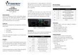
DIP Switch Settings for Alarm Relay Output and Link
Loss Forwarding
Ȋ
This is a Class 1 Laser/LED product.
Don’t stare into the Laser/LED Beam.
ATTENTION
# 1
Port Event Alarm
#2
Power Event Alarm
#3
LFF
(Link Fault Forwarding)
Pin No. # Status
ON
ON
ON
Off
Off
Off
Description
To enable port link down alarm at this port.
To enable power failure alarm.
To disable port link down alarm at this port.
To disable power failure alarm.
To disable Link Fault Forwarding function.
To enable Link Fault Forwarding function at both of fiber and copper
port. Once either one of copper or fiber port is disconnected, the
MCI-211G will forced to turn-off the other port to alert the end of
attached device.
Note: Once the LFF is active and the cable event is recovered,
the LFF DIP-switch must be re-triggered to arouse this function.
The SFP Fiber port supports 2 LEDs for link/activity and full duplex/collision; once the gigabit fiber
port is link up, the link LED will be trigger to “ON”.
/