Dell EMC PowerSwitch N3100 Series Owner's manual

Category
Network switches
Type
Owner's manual

This manual is also suitable for

Dell Networking
N2128PX-ON/N3132PX-ON
Switches
Getting Started Guide
Guide de mise en route
Guia de Noções Básicas
Guía de introducción
Regulatory Model: N2128PX-ON/
N3132PX-ON
Regulatory Type: E05W003/E06W003
Dell Networking
N2128PX-ON/N3132PX-ON
Switches
Getting Started Guide
Regulatory Models: N2128PX-ON/
N3132PX-ON
Notes, Cautions, and Warnings
NOTE: A NOTE indicates important information that helps you make better use of
your switch.
CAUTION: A CAUTION indicates either potential damage to hardware or loss of
data and tells you how to avoid the problem.
WARNING: A WARNING indicates a potential for property damage, personal
injury, or death.
____________________
Copyright © 2016 Dell Inc. All rights reserved. This product is protected by U.S. and international
copyright and intellectual property laws.
Dell™ and the Dell logo are trademarks of Dell Inc. in the United States and/or other jurisdictions.
All other marks and names mentioned herein may be trademarks of their respective companies.
Regulatory Models N2128PX-ON/N3132PX-ON
April 2016 P/N 1VT9M Rev. A00
Contents 3
Contents
1 Introduction. . . . . . . . . . . . . . . . . . . . . . . . 7
N2128PX-ON Hardware Overview. . . . . . . . . . . . . 7
Power Consumption for N2128PX-ON
PoE Switches
. . . . . . . . . . . . . . . . . . . . . 7
N2128PX-ON Model Summary
. . . . . . . . . . . . . . . 8
2 N2128PX-ON Installation . . . . . . . . . . . . . . 9
Rack Mounting an N2128PX-ON Switch . . . . . . . . . 9
Installing in a Rack
. . . . . . . . . . . . . . . . . . 9
Installing as a Free-standing Switch . . . . . . . . 10
Stacking Multiple N2128PX-ON Switches . . . . . . . 10
3 Starting and Configuring the
N2128PX-ON Switch . . . . . . . . . . . . . . . . 11
Connecting an N2128PX-ON Switch to a Terminal . . . 12
Connecting an N2128PX-ON Switch to a
Power Source
. . . . . . . . . . . . . . . . . . . . . . 13
AC and DC Power Connection
. . . . . . . . . . . 13
Booting the N2128PX-ON Switch
. . . . . . . . . . . . 14
4 Contents
Performing the N2128PX-ON Initial Configuration . . . 15
Enabling Remote Management
. . . . . . . . . . . 15
Initial Configuration Procedure
. . . . . . . . . . . 16
Example Session . . . . . . . . . . . . . . . . . . 17
Dell Easy Setup Wizard Console Example
. . . . . 18
Next Steps
. . . . . . . . . . . . . . . . . . . . . 22
4 N3132PX-ON Hardware Overview . . . . . 24
Power Consumption for N3132PX-ON PoE Switches . . . 24
Ventilation System
. . . . . . . . . . . . . . . . . 26
N3132PX-ON Model Summary
. . . . . . . . . . . . . . 27
5 N3132PX-ON Installation . . . . . . . . . . . . 28
Rack Mounting a N3132PX-ON Switch . . . . . . . . . 28
Rack Mounting Safety Considerations
. . . . . . . 28
Installing the Dell ReadyRail System . . . . . . . . 29
Installing as a Free-standing Switch
. . . . . . . . 33
Stacking Multiple N3132PX-ON Switches
. . . . . . . 33
6 Starting and Configuring the
N3132PX-ON Switch . . . . . . . . . . . . . . . . 34
Connecting an N3132PX-ON Switch to a Terminal . . . 35
Connecting an N3132PX-ON Switch to a
Power Source
. . . . . . . . . . . . . . . . . . . . . . 36
AC and DC Power Connection
. . . . . . . . . . . 37
Booting the N3132PX-ON Switch . . . . . . . . . . . . 37
Contents 5
Performing the N3132PX-ON Initial Configuration . . . 38
Enabling Remote Management
. . . . . . . . . . . 38
Initial Configuration Procedure
. . . . . . . . . . . 39
Example Session . . . . . . . . . . . . . . . . . . 40
Dell Easy Setup Wizard Console Example
. . . . . 41
Next Steps
. . . . . . . . . . . . . . . . . . . . . 45
7 NOM Information (Mexico Only) . . . . . . . 47
Getting Started Guide 7
Introduction
This document provides basic information about the Dell
®
Networking
N2128PX-ON/N3132PX-ON switches, including how to install a switch and
perform the initial configuration. For information about how to configure and
monitor switch features, refer to the User Configuration Guide, which is
available on the Dell Support website at dell.com/support, for the latest
updates on documentation and firmware.
NOTE: Switch administrators are strongly advised to maintain Dell Networking
switches on the latest version of the Dell Networking Operating System (DNOS).
Dell Networking continually improves the features and functions of DNOS based on
feedback from you, the customer. For critical infrastructure, pre-staging of the new
release into a non-critical portion of the network is recommended to verify network
configuration and operation with the new DNOS version.
N2128PX-ON Hardware Overview
This section contains information about device characteristics and modular
hardware configurations for the Dell Networking N2128PX-ON switch.
Power Consumption for N2128PX-ON PoE Switches
Table 1-1 describes the power consumption for N2128PX-ON PoE switches.
The system power consumption is 90 watt (W). The PoE power budget is
800W for the main power supply (PSU).
Table 1-1. Power Consumption for N2128PX-ON PoE Switches
Table 1-2 shows power consumption data for the PoE-enabled N2128PX-ON
switches operating from the Modular Power Supply (MPS) only. The PoE
power budget is 800W for MPS.
Model Input Voltage Power Supply
Configuration
Maximum Steady
Current
Consumption (A)
Maximum
Steady
Power (W)
N2128PX-ON 100V/60Hz Main PSU 9.73A 965.5W
110V/60Hz Main PSU 8.75A 960.4W
120V/60Hz Main PSU 8.03A 958.3W
220V/50Hz Main PSU 4.33A 931W
240V/50Hz Main PSU 3.97A 928.7W
8 Getting Started Guide
Table 1-2. Power Consumption Data for N2128PX-ON Switches PoE (+ MPS)
Table 1-3 shows power consumption data for the PoE-enabled N2128PX-ON
switches. The PoE power budget is 1600W for the main power supply +
Modular Power Supply (MPS).
Table 1-3. Power Consumption for N2128PX-ON PoE Switches
N2128PX-ON Model Summary
Table 1-4. N2128PX-ON Switch Regulatory Numbers
Model Input
Voltage
Power Supply
Configuration
Maximum Steady
Current Consumption
(A)
Maximum
Steady
Power (W)
N2128PX-
ON
100V/60Hz MPS 9.92A 986.5W
110V/60Hz MPS 8.93A 975.7W
120V/60Hz MPS 8.01A 955.4W
220V/50Hz MPS 4.44A 945.4W
240V/50Hz MPS 4.08A 951.4W
Model Input Voltage Power Supply
Configuration
Maximum Steady
Current
Consumption (A)
Maximum
Steady
Power (W)
N2128PX-ON 100V/60Hz Main PSU + MPS 11.83A 1175W
110V/60Hz Main PSU + MPS 10.71A 1169W
120V/60Hz Main PSU + MPS 9.84A 1168.9W
220V/50Hz Main PSU + MPS 5.4A 1138.4W
240V/50Hz Main PSU + MPS 5.93A 1141W
Marketing
Model
Name
(MMN)
Description Power Supply
Unit (PSU)
Regulatory
Model
Number
(RMN)
Regulatory
Type
Number
(RTN)
N2128PX-
ON
24x1G/4x2.5G/2x10G
SFP+/2xStacking/24x
PoE+/4xPoE 60W Ports
1000W E05W E05W003
Getting Started Guide 9
N2128PX-ON Installation
Rack Mounting an N2128PX-ON Switch
WARNING: Read the safety information in the
Safety and Regulatory Information
as well as the safety information for other switches that connect to or support the
switch.
The AC power connector is on the rear panel of the switch.
Installing in a Rack
WARNING: Do not use rack mounting kits to suspend the switch from under a
table or desk, or attach it to a wall.
CAUTION: Disconnect all cables from the switch before continuing. Remove all
self-adhesive pads from the underside of the switch, if they have been attached.
CAUTION: When mounting multiple switches into a rack, mount the switches
from the bottom up.
1
Place the supplied rack-mounting bracket on one side of the switch,
ensuring that the mounting holes on the switch line up to the mounting
holes in the rack-mounting bracket. Figure 1-1 illustrates where to mount
the brackets.
Figure 1-1. Attaching the Brackets
2
Insert the supplied bolts into the rack-mounting holes and tighten with a
screwdriver.
10 Getting Started Guide
3
Repeat the process for the rack-mounting bracket on the other side of the
switch.
4
Insert the switch into the 48.26 cm (19 inch) rack, ensuring that the rack-
mounting holes on the switch line up to the mounting holes in the rack.
5
Secure the switch to the rack with either the rack bolts or cage nuts and
cage-nut bolts with washers (depending on the kind of rack you have).
Fasten the bolts on bottom before fastening the bolts on top.
CAUTION: Make sure that the supplied rack bolts fit the pre-threaded holes in the
rack.
NOTE: Make sure that the ventilation holes are not obstructed.
Installing as a Free-standing Switch
NOTE: Dell strongly recommends mounting the switch in a rack.
Install the switch on a flat surface if you are not installing it in a rack. The
surface must be able to support the weight of the switch and the switch
cables. The switch is supplied with four self-adhesive rubber pads.
1
Attach the self-adhesive rubber pads on each location marked on the
bottom of the switch.
2
Set the switch on a flat surface, and make sure that it has proper
ventilation by leaving 5 cm (2 inches) on each side and 13 cm (5 inches) at
the back.
Stacking Multiple N2128PX-ON Switches
You can stack N2128PX-ON switches up to 12 switches high using the mini-
SAS ports located on the rear of the switch. When multiple switches are
connected together through the stack ports, they operate as a single unit with
up to 336 front panel ports. The stack operates and is managed as a single
entity. Refer to the User Configuration Guide and the CLI Reference Guide for
more information.
Getting Started Guide 11
Starting and Configuring the
N2128PX-ON Switch
The following flow chart provides an overview of the steps you use to perform
the initial configuration after the switch is unpacked and mounted.
Figure 1-2. Installation and Configuration Flow Chart
12 Getting Started Guide
Connecting an N2128PX-ON Switch to a Terminal
After completing all external connections, configure the switch by connecting
it to a terminal.
NOTE: Read the Release Notes for this product before proceeding. You can
download the Release Notes from the Dell Support website at dell.com/support.
NOTE: Dell recommends that you obtain the most recent version of the user
documentation from the Dell Support website at dell.com/support.
To monitor and configure the switch via serial console, use the console port
on the front panel of the switch to connect it to a VT100 terminal or to a
computer running VT100 terminal emulation software. The console port is
implemented as a data terminal equipment (DTE) connector.
The following equipment is required to use the console port:
VT100-compatible terminal or a computer with a serial port running
VT100 terminal emulation software,
such as HyperTerminal
®
.
A serial cable (provided) with an RJ-45 connector for the console port and
DB-9 connector for the terminal.
Perform the following tasks to connect a terminal to the switch console port:
1
Connect the DB-9 connector on the serial cable to the terminal or
computer running VT100 terminal emulation software.
2
Configure the terminal emulation software as follows:
a
Select the appropriate serial port (for example, COM 1) to connect to
the console.
b
Set the data rate to 115,200 baud.
c
Set the data format to 8 data bits, 1 stop bit, and no parity.
d
Set the flow control to none.
e
Set the terminal emulation mode to
VT100
.
f
Select Terminal keys for Function, Arrow, and Ctrl keys. Make sure
that the setting is for Terminal keys (not Microsoft Windows keys).
3
Connect the RJ-45 connector on the cable directly to the switch console
port. The Dell Networking console port is located on the right side of the
front panel and is labeled with a
|O|O|
symbol.
Getting Started Guide 13
NOTE: Serial console access to the stack manager is available from any
serial port via the local CLI. Only one serial console session at a time is
supported.
Connecting an N2128PX-ON Switch to a Power
Source
CAUTION: Read the safety information in the
Safety and Regulatory Information
manual as well as the safety information for other switches that connect to or
support the switch.
The N2128PX-ON model has one internal power supply. The
power receptacle
is on the rear panel.
AC and DC Power Connection
1
Make sure that the switch console port is connected to a VT100 terminal
or VT100 terminal emulator via the RJ-45 to DB-9 female cable.
2
Using a 5-foot (1.5 m) standard power cable with safety ground connected,
connect the power cable to the AC main receptacle located on the rear
panel.
3
Connect the power cable to a grounded AC outlet.
4
If you are using a redundant or external DC power supply, such as the Dell
Networking RPS720 or Dell Networking MPS1000 (N2128PX-ON only),
connect the DC power cable to the DC receptacle located on the rear
panel.
14 Getting Started Guide
Booting the N2128PX-ON Switch
When the power is turned on with the local terminal already connected, the
switch goes through a power-on self-test (POST). POST runs every time the
switch is initialized and checks hardware components to determine if the
switch is fully operational before completely booting. If POST detects a
critical problem, the program flow stops. If POST passes successfully, valid
firmware is loaded into RAM. POST messages are displayed on the terminal
and indicate test success or failure. The boot process runs for approximately
60 seconds.
You can invoke the Boot menu after the first part of the POST is completed.
From the Boot menu, you can perform configuration tasks such as resetting
the system to factory defaults, activating the backup image, or recovering a
password. For more information about the Boot menu functions, refer to the
CLI Reference Guide.
Getting Started Guide 15
Performing the N2128PX-ON Initial Configuration
The initial configuration procedure is based on the following assumptions:
The Dell Networking switch was never configured before.
The Dell Networking switch booted successfully.
The console connection was established, and the
Dell Easy Setup Wizard
prompt appears on the screen of a VT100 terminal or terminal equivalent.
The initial switch configuration is performed through the console port. After
the initial configuration, you can manage the switch from the already-
connected console port or remotely through an interface defined during the
initial configuration.
NOTE: The switch is not configured with a default user name, password, or IP
address.
Before setting up the initial configuration of the switch, obtain the following
information from your network administrator:
The IP address to be assigned to the management interface.
The IP subnet mask for the network.
The IP address of the management interface default gateway.
These settings are necessary to allow the remote management of the switch
through Telnet (Telnet client) or HTTP (Web browser).
Enabling Remote Management
On the N2128PX-ON/N3132PX-ON switches, you can use any of the switch
ports on the front panel for in-band management. By default, all in-band
ports are members of VLAN 1.
The Dell Easy Setup Wizard includes prompts to configure network
information for the VLAN 1 interface on the N2128PX-ON switch. You can
assign a static IP address and subnet mask or enable DHCP and allow a
network DHCP server to assign the information.
Refer to the CLI Reference Guide for commands to configure network
information.
16 Getting Started Guide
Initial Configuration Procedure
Perform the initial configuration by using the Dell Easy Setup Wizard or by
using the CLI. The wizard automatically starts when the switch configuration
file is empty. You can exit the wizard at any point by entering [ctrl+z], but all
configuration settings specified will be discarded, and the switch will use the
default values.
NOTE: If you do not run the Dell Easy Setup Wizard or do not respond to the initial
Easy Setup Wizard prompt within 60 seconds, the switch enters CLI mode. You must
reset the switch with an empty startup configuration in order to rerun the Dell Easy
Setup Wizard.
For more information about performing the initial configuration by using the
CLI, refer to the CLI Reference Guide. This Getting Started Guide shows how
to use the Dell Easy Setup Wizard for initial switch configuration. The wizard
sets up the following configuration on the switch:
Establishes the initial privileged user account with a valid password. The
wizard configures one privileged user account during the setup.
Enables CLI login and HTTP access to use the local authentication setting
only.
Sets up the IP address for the VLAN 1 routing interface, of which all
in-band ports are members.
Sets up the SNMP community string to be used by the SNMP manager at
a given IP address. You may choose to skip this step if SNMP management
is not used for this switch.
Allows you to specify the network management system IP address or
permit management access from all IP addresses.
Configures the default gateway IP address for the VLAN 1 interface.
Getting Started Guide 17
Example Session
This section describes a Dell Easy Setup Wizard session. The following
values are used by the example session:
The SNMP community string to be used is
public
.
The network management system (NMS) IP address is
10.1.2.100
.
The user name is
admin
, and the password is
admin123
.
The IP address for the VLAN 1 routing interface is
10.1.1.200
with a
subnet mask of
255.255.255.0
.
The default gateway is
10.1.1.1.
The setup wizard configures the initial values as defined above. After
completing the wizard, the switch is configured as follows:
SNMPv2 is enabled and the community string is set up as defined above.
SNMPv3 is disabled by default.
The admin user account is set up as defined.
A network management system is configured. From the management
station, you can access the SNMP, HTTP, and CLI interfaces. You may also
choose to allow all IP addresses to access these management interfaces by
choosing the (0.0.0.0) IP address.
An IP address is configured for the VLAN 1 routing interface.
A default gateway address is configured.
NOTE: In the following example, the possible user options or default values are
enclosed in [ ]. If you press <Enter> with no options defined, the default value is
accepted. Help text is in parentheses.
18 Getting Started Guide
Dell Easy Setup Wizard Console Example
The following example contains the sequence of prompts and responses
associated with running an example Dell Easy Setup Wizard session, using
the input values listed earlier.
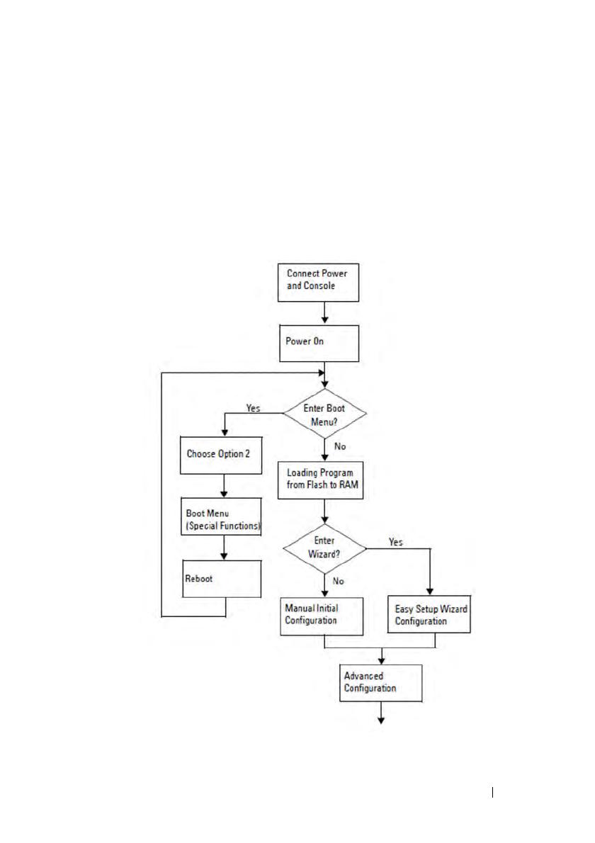
After the switch completes the POST and is booted, the following dialog
appears:
Unit 1 - Waiting to select management unit)>
___________Dell SupportAssist EULA__________________
I accept the terms of the license agreement. You can
reject the license agreement by configuring this
command 'eula-consent support-assist reject'.
By installing SupportAssist, you allow Dell to save
your contact information (e.g. name, phone number
and/or email address) which would be used to provide
technical support for your Dell products and services
Dell may use the information for providing
recommendations to improve your IT infrastructure.
Dell SupportAssist also collects and stores machine
diagnostic information, which may include but is not
limited to configuration information, user supplied
contact information, names of data volumes, IP
addresses, access control lists, diagnostics &
performance information, network configuration
information, host/server configuration & performance
information and related data (Collected Data) and
transmits this information to Dell. By downloading
SupportAssist and agreeing to be bound by these terms
and the Dell end user license agreement, available at:
http://www.dell.com/aeula, you agree to allow Dell to
provide remote monitoring services of your IT
environment and you give Dell the right to collect the
Collected Data in accordance with Dell's Privacy
Policy, available at:
http://www.dell.com/privacypolicycountryspecific, in
order to enable the performance of all of the various
functions of SupportAssist during your entitlement to
Getting Started Guide 19
receive related repair services from Dell. You further
agree to allow Dell to transmit and store the
Collected Data from SupportAssist in accordance with
these terms. You agree that the provision of
SupportAssist may involve international transfers of
data from you to Dell and/or to Dell's affiliates,
subcontractors or business partners. When making such
transfers, Dell shall ensure appropriate protection is
in place to safeguard the Collected Data being
transferred in connection with SupportAssist. If you
are downloading SupportAssist on behalf of a company
or other legal entity, you are further certifying to
Dell that you have appropriate authority to provide
this consent on behalf of that entity. If you do not
consent to the collection, transmission and/or use of
the Collected Data, you may not download, install or
otherwise use SupportAssist.
________AeroHive HiveManager NG EULA________________
This switch includes a feature that enables it to work
with HiveManager (an optional management suite), by
sending the switch's service tag number and IP Address
to HiveManager to authenticate your entitlement to use
HiveManager. If you wish to disable this feature, you
should run command 'eula-consent hiveagent reject'
immediately upon powering up the switch for the first
time, or at any time thereafter.
Applying Global configuration, please wait...
Welcome to Dell Easy Setup Wizard
The setup wizard guides you through the initial switch
configuration, and gets you up and running as quickly
as possible. You can skip the setup wizard, and enter
CLI mode to manually configure the switch. You must
respond to the next question to run the setup wizard
within 60 seconds, otherwise the system will continue
20 Getting Started Guide
with normal operation using the default system
configuration. Note: You can exit the setup wizard at
any point by entering [ctrl+z].
Would you like to run the setup wizard (you must
answer this question within 60 seconds)? [Y/N] y
Step 1:
The system is not set up for SNMP management by
default. To manage the switch using SNMP (required for
Dell Network Manager) you can
. Set up the initial SNMP version 2 account now.
. Return later and set up other SNMP accounts. (For
more information on setting up an SNMP version 1 or
3 account, see the user documentation).
Would you like to set up the SNMP management interface
now? [Y/N] y
To set up the SNMP management account you must specify
the management system IP address and the “community
string” or password that the particular management
system uses to access the switch. The wizard
automatically assigns the highest access level
[Privilege Level 15] to this account. You can use Dell
Network Manager or other management interfaces to
change this setting, and to add additional management
system information later. For more information on
adding management systems, see the user documentation.
To add a management station:
Please enter the SNMP community string to be used.
[public]: public
NOTE: If it is configured, the default access level is set to the highest available
access for the SNMP management interface. Initially only SNMPv2 will be
activated. SNMPv3 is disabled until you return to configure security access for
SNMPv3 (e.g. engine ID, view, etc.).
Please enter the IP address of the Management System
(A.B.C.D) or wildcard (0.0.0.0) to manage from any
Management Station. [0.0.0.0]: 10.1.2.100
  • Page 1 1
  • Page 2 2
  • Page 3 3
  • Page 4 4
  • Page 5 5
  • Page 6 6
  • Page 7 7
  • Page 8 8
  • Page 9 9
  • Page 10 10
  • Page 11 11
  • Page 12 12
  • Page 13 13
  • Page 14 14
  • Page 15 15
  • Page 16 16
  • Page 17 17
  • Page 18 18
  • Page 19 19
  • Page 20 20
  • Page 21 21
  • Page 22 22
  • Page 23 23
  • Page 24 24
  • Page 25 25
  • Page 26 26
  • Page 27 27
  • Page 28 28
  • Page 29 29
  • Page 30 30
  • Page 31 31
  • Page 32 32
  • Page 33 33
  • Page 34 34
  • Page 35 35
  • Page 36 36
  • Page 37 37
  • Page 38 38
  • Page 39 39
  • Page 40 40
  • Page 41 41
  • Page 42 42
  • Page 43 43
  • Page 44 44
  • Page 45 45
  • Page 46 46
  • Page 47 47
  • Page 48 48
  • Page 49 49
  • Page 50 50
  • Page 51 51
  • Page 52 52
  • Page 53 53
  • Page 54 54
  • Page 55 55
  • Page 56 56
  • Page 57 57
  • Page 58 58
  • Page 59 59
  • Page 60 60
  • Page 61 61
  • Page 62 62
  • Page 63 63
  • Page 64 64
  • Page 65 65
  • Page 66 66
  • Page 67 67
  • Page 68 68
  • Page 69 69
  • Page 70 70
  • Page 71 71
  • Page 72 72
  • Page 73 73
  • Page 74 74
  • Page 75 75
  • Page 76 76
  • Page 77 77
  • Page 78 78
  • Page 79 79
  • Page 80 80
  • Page 81 81
  • Page 82 82
  • Page 83 83
  • Page 84 84
  • Page 85 85
  • Page 86 86
  • Page 87 87
  • Page 88 88
  • Page 89 89
  • Page 90 90
  • Page 91 91
  • Page 92 92
  • Page 93 93
  • Page 94 94
  • Page 95 95
  • Page 96 96
  • Page 97 97
  • Page 98 98
  • Page 99 99
  • Page 100 100
  • Page 101 101
  • Page 102 102
  • Page 103 103
  • Page 104 104
  • Page 105 105
  • Page 106 106
  • Page 107 107
  • Page 108 108
  • Page 109 109
  • Page 110 110
  • Page 111 111
  • Page 112 112
  • Page 113 113
  • Page 114 114
  • Page 115 115
  • Page 116 116
  • Page 117 117
  • Page 118 118
  • Page 119 119
  • Page 120 120
  • Page 121 121
  • Page 122 122
  • Page 123 123
  • Page 124 124
  • Page 125 125
  • Page 126 126
  • Page 127 127
  • Page 128 128
  • Page 129 129
  • Page 130 130
  • Page 131 131
  • Page 132 132
  • Page 133 133
  • Page 134 134
  • Page 135 135
  • Page 136 136
  • Page 137 137
  • Page 138 138
  • Page 139 139
  • Page 140 140
  • Page 141 141
  • Page 142 142
  • Page 143 143
  • Page 144 144
  • Page 145 145
  • Page 146 146
  • Page 147 147
  • Page 148 148
  • Page 149 149
  • Page 150 150
  • Page 151 151
  • Page 152 152
  • Page 153 153
  • Page 154 154
  • Page 155 155
  • Page 156 156
  • Page 157 157
  • Page 158 158
  • Page 159 159
  • Page 160 160
  • Page 161 161
  • Page 162 162
  • Page 163 163
  • Page 164 164
  • Page 165 165
  • Page 166 166
  • Page 167 167
  • Page 168 168
  • Page 169 169
  • Page 170 170
  • Page 171 171
  • Page 172 172
  • Page 173 173
  • Page 174 174
  • Page 175 175
  • Page 176 176
  • Page 177 177
  • Page 178 178
  • Page 179 179
  • Page 180 180
  • Page 181 181
  • Page 182 182
  • Page 183 183
  • Page 184 184
  • Page 185 185
  • Page 186 186
  • Page 187 187
  • Page 188 188
  • Page 189 189
  • Page 190 190
  • Page 191 191
  • Page 192 192
  • Page 193 193
  • Page 194 194
  • Page 195 195
  • Page 196 196
  • Page 197 197
  • Page 198 198
  • Page 199 199
  • Page 200 200
  • Page 201 201

Dell EMC PowerSwitch N3100 Series Owner's manual

Category
Network switches
Type
Owner's manual
This manual is also suitable for

Ask a question and I''ll find the answer in the document

Finding information in a document is now easier with AI