Page is loading ...

Su cabezal motor ha sido diseñada y fabricada de conformidad
con las estrictas normas para brindar fiabilidad, facilidad de uso
y seguridad para el operador. Con el debido cuidado, le brindará
muchos años de sólido y eficiente funcionamiento.
ADVERTENCIA: Para reducir el riesgo de lesiones,
el usuario debe leer y comprender el manual del operador antes
de usar este producto.
Le agradecemos su compra.
Le bloc-moteur a été conçue et fabriquée conformément à
nos strictes normes de fiabilité, simplicité d’emploi et sécurité
d’utilisation. Correctement entretenue, elle vous donnera des années
de fonctionnement robuste et sans problème.
AVERTISSEMENT : Pour réduire les risques de
blessures, l’utilisateur doit lire et veiller à bien comprendre le
manuel d’utilisation avant d’employer ce produit.
Merci de votre achat.
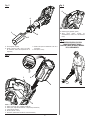
OPERATOR’S MANUAL
MANUEL D’UTILISATION/MANUAL DEL OPERADOR
40 VOLT POWER HEAD
40 V BLOC MOTEUR
40 V CABEZAL MOTOR
RY40003
CONSERVER CE MANUEL POUR
FUTURE RÉFÉRENCE
GUARDE ESTE MANUAL PARA
FUTURAS CONSULTAS
SAVE THIS MANUAL FOR FUTURE REFERENCE
Your power head has been engineered and manufactured to our high standard for dependability, ease of operation, and
operator safety. When properly cared for, it will give you years of rugged, trouble-free performance.
WARNING: To reduce the risk of injury, the user must read and understand the operator’s manual before using
this product.
Thank you for your purchase.
Page is loading ...

iii
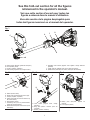
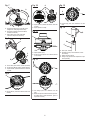
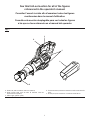
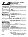
Fig. 8
A - Trigger lock-out (gâchette avec verrou,
gatillo con seguro)
B - Switch trigger (gâchette, gatillo del
interruptor)
C - Speed switch (interrupteur de vitesse,
interruptor de velocidad)
Fig. 6
A
C
B
Fig. 5
A - Knob (bouton, perilla)
B - Adjustable front handle (poignée avant
réglable, mango delantero ajustable)
A
B
Fig. 9
Fig. 10
Fig. 11
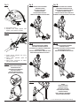
Fig. 7
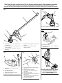
PROPER EDGER ATTACHMENT
OPERATING POSITION
ACCESSOIRE COUPE-BORDURES
POSITION DE TRAVAIL
POSICIÓN CORRECTA PARA EL
ACCESORIO PARA CORTAR BORDES
PROPER BLOWER ATTACHMENT
OPERATING POSITION
ACCESSOIRE SOUFFLANTE
POSITION DE TRAVAIL
POSICIÓN CORRECTA PARA EL
MANEJO DE ADITAMENTO PARA SOPLADOR
PROPER CULTIVATOR ATTACHMENT
OPERATING POSITION
ACCESSOIRE CULTIVATEUR POSITION DE TRAVAIL
POSICIÓN CORRECTA PARA EL
MANEJO DE ADITAMENTO PARA CULTIVAR
PROPER CURVED SHAFT TRIMMER
ATTACHMENT OPERATING POSITION
ACCESSOIRE TAILLE-BORDURES À ARBRE
COURBÉE POSITION DE TRAVAIL
POSICIÓN CORRECTA PARA EL MANEJO DE
ADITAMENTO PARA RECORTADORA DE EJE CURVO
PROPER STRAIGHT SHAFT TRIMMER
ATTACHMENT OPERATING POSITION
ACCESSOIRE TAILLE-BORDURES À ARBRE DROIT
POSITION DE TRAVAIL
POSICIÓN CORRECTA PARA EL MANEJO DE ADITA-
MENTO PARA RECORTADORA DE EJE RECTO
A
A - 60° maximum (60° maximum, 60° máximo)
PROPER
PRUNER ATTACHMENT
OPERATING POSITION
ACCESSOIRE D’ÉLAGAGE
DROIT POSITION DE TRAVAIL
POSICIÓN CORRECTA
PARA EL MANEJO DE ADITAMENTO
PARA ACCESORIO PARA PODAR
Fig. 12
Page is loading ...

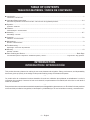
3 — English
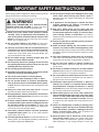
WARNING!
When using electric gardening appliances, basic safety
precautions should always be followed to reduce the risk
of fire, electric shock and personal injury.
READ ALL INSTRUCTIONS
For safe operation, read and understand all instructions
before using this product. Follow all safety instructions.
Failure to follow all safety instructions listed below, can
result in serious personal injury.
Do not allow children or untrained individuals to use this
unit.
Check the work area before each use. Remove all objects
such as rocks, broken glass, nails, wire, or string which
can be thrown or become entangled in the machine.
Always wear eye protection with side shields marked to
comply with ANSI Z87.1. Following this rule will reduce
the risk of serious personal injury.
Use Safety Glasses – Always use face or dust mask if
operation is dusty.
Protect your lungs. Wear a face or dust mask if the op-
eration is dusty. Following this rule will reduce the risk of
serious personal injury.
Dress Properly – Use of rubber gloves and substantial
footwear is recommended when working outdoors. Wear
heavy, long pants, long sleeves, boots, and gloves. Do
not wear loose fitting clothing, short pants, sandals, or
go barefoot. Do not wear loose clothing or jewelry. They
can be caught in moving parts. Secure long hair above
shoulder level to prevent entanglement in moving parts.
Keep children away – Keep all bystanders, children, and
pets at least 50 ft. away.
Stay alert – Watch what you are doing. Use common sense.
Do not operate this unit when you are tired, ill, upset, or
under the influence of alcohol, drugs, or medication.
Do not operate in poor lighting.
Keep all parts of your body away from any moving part.
Do not operate power tools in explosive atmospheres,
such as in the presence of flammable liquids, gases, or
dust. Power tools create sparks which may ignite the dust
or fumes.
Avoid Dangerous Environments – Don’t expose appliance
to rain or wet conditions. Water entering an appliance will
increase the risk of electric shock.
Use Right Appliance – Do not use this product for any
job except that for which it is intended.
Don’t Force Appliance – It will do the job better and with
less likelihood of a risk of injury at the rate for which it
was designed.
IMPORTANT SAFETY INSTRUCTIONS
Do not operate the equipment while barefoot or when
wearing sandals or similar lightweight footwear. Wear
protective footwear that will protect your feet and improve
your footing on slippery surfaces.
Do not overreach – Keep firm footing and balance. Over-
reaching can result in loss of balance.
Avoid accidental starting – Be sure switch trigger is in
the locked or off position before inserting battery pack.
Carrying tools with your finger on the switch trigger or
inserting the battery pack into a tool with the switch on
invites accidents.
Do not use tool if switch trigger does not turn it on or off.
Any tool that cannot be controlled with the switch trigger
is dangerous and must be repaired.
Disconnect power head – Disconnect battery pack from
the appliance before storing, servicing, or changing ac-
cessories such as cutting line. Such preventive safety
measures reduce the risk of starting the tool accidentally.
Use only identical manufacturer’s replacement parts and
accessories. Use of any other parts may create a hazard
or cause product damage.
Maintain appliance with care – Replace string head if
cracked, chipped, or damaged in any way. Be sure the
string head is properly installed and securely fastened.
Failure to do so can cause serious injury. Follow instruc-
tions for lubrication and changing accessories. Inspect
charger cord periodically and, if damaged, have it replaced.
Keep power head handles dry, clean, and free from grease
and oil.
Check Damaged Parts – Before further use of the appli-
ance, a guard or other part that is damaged should be
carefully checked to determine that it will operate properly
and perform its function. Check for alignment of moving
parts, binding of moving parts, breakage of parts, mount-
ing and any other condition that may effect its operation.
A guard or other part that is damaged should be properly
repaired or replaced by an authorized service center un-
less indicated elsewhere in this manual.
Keep hands and feet away from cutting area.
Make sure all guards, straps, deflectors and handles are
properly and securely attached.
Use only the manufacturer’s replacement string in the
cutting head when using a string trimmer attachment.
Do not use any other cutting attachment, for example,
metal wire, rope, or the like. To install any other brand of
cutting head to the string trimmer attachment can result
in serious personal injury.
Never operate unit without the debris shield in place and
in good condition.
Maintain a firm grip on both handles while trimming. Keep
string head below waist level. Never cut with the string
head located over 30 in. or more above the ground.

4 — English
Use extra care when cleaning on stairs.
Remove or disconnect battery before servicing, cleaning
or removing material from the gardening appliance.
Use battery only with charger listed. For use with 40V
lithium-ion battery packs. See Tool/Appliance/Battery
Pack/Charger Correlation Supplement 988000-842.
Do not dispose of the batteries in a fire. The cell may
explode. Check with local codes for possible special
disposal instructions.
Do not open or mutilate the batteries. Released electrolyte
is corrosive and may cause damage to the eyes or skin.
It may be toxic if swallowed.
Do not place battery tools or their batteries near fire or
heat. This will reduce the risk of explosion and possibly
injury.
Batteries can explode in the presence of a source of
ignition, such as a pilot light. To reduce the risk of seri-
ous personal injury, never use any cordless product in
the presence of open flame. An exploded battery can
propel debris and chemicals. If exposed, flush with water
immediately.
Do not crush, drop or damage battery pack. Do not
use a battery pack or charger that has been dropped or
received a sharp blow. A damaged battery is subject to
explosion. Properly dispose of a dropped or damaged
battery immediately.
Exercise care in handling batteries in order not to short the
battery with conducting materials such as rings, bracelets,
and keys. The battery or conductor may overheat and
cause burns.
Under extreme usage or temperature conditions, battery
leakage may occur. If liquid comes in contact with your
skin, wash immediately with soap and water, then neu-
tralize with lemon juice or vinegar. If liquid gets into your
eyes, flush them with clean water for at least 10 minutes,
then seek immediate medical attention. Following this
rule will reduce the risk of serious personal injury.
Save these instructions. Refer to them frequently and
use them to instruct others who may use this power tool.
If you loan someone this power tool, loan them these
instructions also.
Keep all parts of the body away from the saw chain. Do
not remove cut material or hold material to be cut when
blades are moving. Make sure the switch is off when
clearing jammed material. Saw chain continues to move
after the switch is turned off. A moment of inattention
while operating the extended-reach pruner may result in
serious personal injury.
Carry the extended-reach pruner by the handle with the
saw chain stopped. When transporting or storing the
extended-reach pruner, always fit the saw chain device
cover. Proper handling of the extended-reach pruner will
reduce possible personal injury from the saw chain.
Store idle appliances indoors - When not in use, power
head and attachments should be stored indoors in a dry,
locked place out of the reach of children.
Never use flailing devices, wire or rope on any attachment.
Inspect area to be cut. Remove objects (rocks, broken
glass, nails, wire, string, etc.) which can be thrown or
become entangled in cutting head.
Keep the air vents clean and free of debris to avoid over-
heating the motor. Clean after each use.
Stop the unit and disconnect the power source when not
in use. Carry the unit with the motor stopped.
Store out of the reach of children.
Do not hang unit so that the switch trigger is depressed.
Battery tools do not have to be plugged into an electrical
outlet; therefore, they are always in operating condition.
Be aware of possible hazards when not using your bat-
tery tool or when changing accessories. Following this
rule will reduce the risk of electric shock, fire, or serious
personal injury.
Do not charge battery tool in rain, or damp or wet location.
Following this rule will reduce the risk of electric shock.
Do not use battery-operated appliance in rain.
Do not grasp the exposed cutting blades or cutting edges
when picking up or holding the appliance.
Do not allow power head to be used as a toy. Close at-
tention is necessary when used by or near children.
Do not handle charger, including charger plug, and charger
terminals with wet hands.
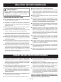
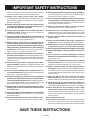
IMPORTANT SAFETY INSTRUCTIONS
ADDITIONAL SPECIFIC SAFETY RULES CAN BE FOUND
IN THE APPLICABLE ATTACHMENT’S OPERATOR’S MANUAL

5 — English
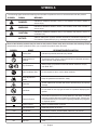
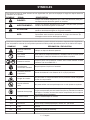
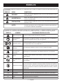
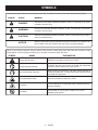
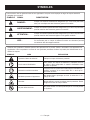
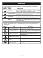
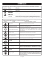
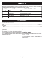
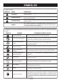
SYMBOLS
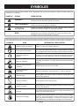
The following signal words and meanings are intended to explain the levels of risk associated with this product.
SYMBOL SIGNAL MEANING
DANGER:
Indicates a hazardous situation, which, if not avoided, will result in death or
serious injury.
WARNING:
Indicates a hazardous situation, which, if not avoided, could result in death or
serious injury.
CAUTION:
Indicates a hazardous situation, that, if not avoided, may result in minor or
moderate injury.
NOTICE:
(Without Safety Alert Symbol) Indicates information considered important, but
not related to a potential injury (e.g. messages relating to property damage).
Some of the following symbols may be used on this product. Please study them and learn their meaning. Proper
interpretation of these symbols will allow you to operate the product better and safer.
SYMBOL NAME DESIGNATION/EXPLANATION
Safety Alert Indicates a potential personal injury hazard.
Read Operator’s
Manual
To reduce the risk of injury, user must read and understand operator’s
manual before using this product.
Eye Protection
Always wear eye protection with side shields marked to comply
with ANSI Z87.1.
Wet Conditions Alert Do not expose to rain or use in damp locations.
Keep Bystanders
Away
Keep all bystanders at least 50 ft. away.
Ricochet
Thrown objects can ricochet and result in personal injury or property
damage.
No Blade
Do not install or use any type of blade on a product displaying this
symbol.
Recycle Symbol
This product uses lithium-ion (Li-ion) batteries. Local, state, or federal
laws may prohibit disposal of batteries in ordinary trash. Consult your
local waste authority for information regarding available recycling and/
or disposal options.
Direct Current Type or a characteristic of current
n
o
No Load Speed Rotational speed, at no load
.../min Per Minute Revolutions, strokes, surface speed, orbits etc., per minute
V Volts Voltage
Hz Hertz Frequency (cycles per second)
min Minutes Time

6 — English
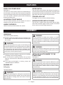
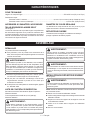
FEATURES
KNOW YOUR POWER HEAD
See Figure 1.
The safe use of this product requires an understanding of
the information on the tool and in this operator’s manual as
well as a knowledge of the project you are attempting. Before
use of this product, familiarize yourself with all operating
features and safety rules.
ADJUSTABLE FRONT HANDLE
The front handle assembly can be adjusted for ease of
operation and to help prevent loss of control.
HANDLE OVERMOLD
Handle overmold provides added user comfort.
SPEED SWITCH
This tool has a speed selector that allows the operator to
choose between and HI and LOW speeds. Using low speed
during operation can help extend battery run time, while using
high speed will improve power and performance.
TRIGGER LOCK-OUT
The trigger lock-out prevents accidental starting.
VARIABLE SPEED SWITCH TRIGGER
This tool has a variable speed switch that delivers higher
speed with increased trigger pressure. Speed is controlled
by the amount of switch trigger depression.
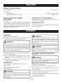
ASSEMBLY
UNPACKING
This product requires assembly.
Carefully remove the product and any accessories from
the box. Make sure that all items listed in the packing list
are included.
WARNING:
Do not use this product if any parts on the Packing List
are already assembled to your product when you unpack
it. Parts on this list are not assembled to the product by
the manufacturer and require customer installation. Use
of a product that may have been improperly assembled
could result in serious personal injury.
Inspect the product carefully to make sure no breakage
or damage occurred during shipping.
Do not discard the packing material until you have
carefully inspected and satisfactorily operated the
product.
If any parts are damaged or missing, please call
1-800-860-4050 for assistance.
PACKING LIST
Power Head
Front Handle
Operator’s Manual
WARNING:
If any parts are damaged or missing do not operate this
product until the parts are replaced. Use of this product
with damaged or missing parts could result in serious
personal injury.
WARNING:
Do not attempt to modify this product or create
accessories not recommended for use with this product.
Any such alteration or modification is misuse and could
result in a hazardous condition leading to possible serious
personal injury.
WARNING:
To prevent accidental starting that could cause serious
personal injury, always remove the battery pack from the
product when assembling parts.
INSTALLING AN ATTACHMENT TO THE
POWER HEAD
See Figure 2.
WARNING:
Read and understand entire Operator’s Manual for each
optional attachment used on this power head and follow
all warnings and instructions. Failure to follow all instruc-
tions could result in electric shock, fire and/or serious
personal injury.
WARNING:
This 40 V power head is designed to be used only with the
attachment models that are specified in this Operator’s
Manual. It is not designed to be used with brush cutters
or other attachment models. Use of other attachments
could cause serious personal injuries or property damage.

7 — English
NOTE: If the button does not release completely in the
positioning hole, the shafts are not locked into place.
Slightly rotate from side to side until the button is locked
into place.
Tighten the knob securely.
WARNING:
Be certain the knob is fully tightened before operating
equipment; check it periodically for tightness during use
to avoid serious personal injury.
REMOVING THE ATTACHMENT FROM THE
POWER HEAD
Stop the motor and remove the battery pack.
Loosen the knob.
Push in the button and twist the shafts to remove and
separate ends.
ATTACHING THE FRONT HANDLE
See Figure 3.
Loosen and remove the wing bolt and washer from the
handle.
Install the handle on the power head shaft in the area
indicated by the illustration.
Adjust handle up or down, if necessary, to desired
operating position.
Reinstall the washer and wing bolt. Tighten wing bolt to
secure.
ASSEMBLY
WARNING:
Never install, remove, or adjust any attachment while
power head is running. Failure to stop the motor can
cause serious personal injury. Never operate power head
without an attachment.
This 40 V power head may be used with only the following
Ryobi Expand-It attachments:
RY15518, RYEDG11, and RYEDG12 Edgers
RY15519, RYBLW22, and RYAXA22 Blowers
RY15523, RY15523A and RYSST44 Straight Shaft String
Trimmers
RY15525 and RYCST55 Curved Shaft String Trimmers
RY15550 and RYTIL66 Cultivators
RY15520 and RYPRN33 Pruners
RYSNW00 Snow Thrower
RYSWP25 Sweeper
The attachment connects to the power head by means of
a coupler device.
Stop the motor and remove the battery pack.
Loosen the knob on the coupler of the power head shaft
and remove the end cap from the attachment.
Push in the button located on the attachment shaft. Align
the button with the guide recess on the power head coupler
and slide the two shafts together. Rotate the attachment
shaft until the button locks into the positioning hole.
OPERATION
WARNING:
Read and understand entire Operator’s Manual for each
optional attachment used on this power head and follow
all warnings and instructions. Failure to follow all instruc-
tions could result in electric shock, fire and/or serious
personal injury.
WARNING:
Do not allow familiarity with products to make you care-
less. Remember that a careless fraction of a second is
sufficient to inflict serious injury.
WARNING:
Always wear eye protection with side shields marked to
comply with ANSI Z87.1. Hearing and/or head protection
may also be required depending on the type of attach-
ment used and as prescribed in the attachment’s Opera-
tor’s Manual. Failure to do so could result in objects being
thrown into your eyes and other possible serious injuries.
WARNING:
Do not use any attachments or accessories not recom-
mended by the manufacturer of this product. The use of
attachments or accessories not recommended can result
in serious personal injury.

8 — English
ADJUSTING THE FRONT HANDLE
See Figure 5.
The angle of the front handle can be adjusted 180°.
Remove the battery pack.
Set the power head on a flat surface and turn the knob
counterclockwise to loosen the handle.
Adjust the handle as desired.
Turn the knob clockwise until the handle is securely
tightened before reinstalling the battery pack.
STARTING/STOPPING THE POWER HEAD
See Figure 6.
To start:
Select the desired operating speed (HI or LOW).
Press and hold the trigger lock-out.
Depress the switch trigger.
To stop:
Release the switch trigger to stop the power head.
Upon release of the switch trigger, the trigger lock-out
will automatically reset to the locked position.
OPERATING THE POWER HEAD
See Figures 7 - 12.
Hold the power head with your right hand on the rear handle
and your left hand on the front handle. Keep a firm grip with
both hands while in operation. Power head should be held at
a comfortable position with the rear handle about hip height.
Always operate power head with switch trigger completely
depressed. If debris becomes wrapped around the
attachment, RELEASE THE SWITCH TRIGGER, remove the
battery pack, and remove the debris.
WARNING:
Always hold the power head away from the body keeping
clearance between the body and the tool. Any contact
with an attachment cutting head can result in burns and/
or other serious personal injury.
WARNING:
Extreme care must be taken when using a blade attach-
ment to ensure safe operation. Read the safety informa-
tion for safe operation when using a blade attachment
and refer to the safety rules and instructions in your at-
tachment manual. Never use a brush cutter attachment
with this power head. Improper operation of a blade or
any attachment could result in serious injury.
NOTICE:
Before each use, inspect the entire product for damaged,
missing, or loose parts such as screws, nuts, bolts, caps,
etc. Tighten securely all fasteners and caps and do not
operate this product until all missing or damaged parts
are replaced. Please contact customer service or a quali-
fied service center for assistance.
WARNING:
Always remove battery pack from your tool when you are
assembling parts, making adjustments, cleaning, or when
not in use. Removing battery pack will prevent accidental
starting that could cause serious personal injury.
INSTALLING/REMOVING BATTERY PACK
See Figure 4.
To install battery pack:
Place the battery pack in the power head. Align raised
ribs on battery pack with grooves in the power head’s
battery port.
WARNING:
Make sure the latch on the bottom of the battery pack
snaps in place and the battery pack is fully seated and
secure in the power head battery port before beginning
operation. Failure to securely seat the battery pack could
cause the battery pack to fall out, resulting in serious
personal injury.
To remove battery pack:
Press and hold the battery latch button at the bottom of
the battery pack.
Remove battery pack from the power head.
For complete charging instructions, refer to the Operator’s
Manuals for your RYOBI battery pack and charger models.
WARNING:
To avoid serious personal injury, always remove the bat-
tery pack and keep hands clear of the trigger lock-out
when carrying or transporting the tool.
OPERATION

9 — English
WARNING:
To avoid serious personal injury, always remove the bat-
tery pack from the tool when cleaning or performing any
maintenance.
WARNING:
Always wear eye protection with side shields marked to
comply with ANSI Z87.1. Hearing and/or head protection
may also be required depending on the type of attach-
ment used and as prescribed in the attachment’s Opera-
tor’s Manual. Failure to do so could result in objects being
thrown into your eyes and other possible serious injuries.
WARNING:
When servicing, use only identical replacement parts.
Use of any other parts can create a hazard or cause
product damage.
NOTICE:
Periodically inspect the entire product for damaged,
missing, or loose parts such as screws, nuts, bolts, caps,
etc. Tighten securely all fasteners and caps and do not
operate this product until all missing or damaged parts
are replaced. Please contact customer service or a quali-
fied service center for assistance.
MAINTENANCE
GENERAL MAINTENANCE
Avoid using solvents when cleaning plastic parts. Most
plastics are susceptible to damage from various types of
commercial solvents and may be damaged by their use. Use
clean cloths to remove dirt, dust, oil, grease, etc.
WARNING:
Do not at any time let brake fluids, gasoline, petroleum-
based products, penetrating oils, etc., come in contact
with plastic parts. Chemicals can damage, weaken or
destroy plastic which can result in serious personal injury.
CLEANING THE POWER HEAD
Stop the motor and remove the battery pack.
Clean dirt and debris from the power head using a damp
cloth with a mild detergent.
NOTICE:
Do not use any strong detergents on the plastic housing
or the handle. They can be damaged by certain aromatic
oils such as pine and lemon, and by solvents such as
kerosene.
STORING THE POWER HEAD
Remove the battery pack from the power head before
storing.
Clean all foreign material from the power head.
Store it in a place that is inaccessible to children.
Keep away from corrosive agents such as garden
chemicals and de-icing salts.
TROUBLESHOOTING
PROBLEM POSSIBLE CAUSE SOLUTION
Motor fails to start when switch
trigger is depressed.
Battery is not secure.
Battery is not charged.
To secure the battery pack, make sure the latch on the
bottom of the battery pack is snapped into place.
Charge the battery pack according to the instructions
included with your model.

10 — English
LIMITED WARRANTY STATEMENT
Techtronic Industries North America, Inc., warrants to the
original retail purchaser that this RYOBI
™
brand outdoor
product is free from defect in material and workmanship
and agrees to repair or replace, at Techtronic Industries
North America, Inc.’s, discretion, any defective product
free of charge within these time periods from the date of
purchase.
Five years if the product is used for personal, family or
household use;
90 days, if used for any other purpose, such as
commercial or rental.
This warranty extends to the original retail purchaser only
and commences on the date of the original retail purchase.
Any part of this product found in the reasonable judgment
of Techtronic Industries North America, Inc. to be defective
in material or workmanship will be repaired or replaced
without charge for parts and labor by an authorized service
center for RYOBI
™
brand outdoor products (Authorized
Ryobi Service Center).
The product, including any defective part, must be returned
to an authorized Ryobi service center within the warranty
period. The expense of delivering the product to the service
center for warranty work and the expense of returning it
back to the owner after repair or replacement will be paid
by the owner. Techtronic Industries North America, Inc.’s,
responsibility in respect to claims is limited to making the
required repairs or replacements and no claim of breach
of warranty shall be cause for cancellation or rescission
of the contract of sale of any RYOBI
™
brand outdoor
product. Proof of purchase will be required by the dealer
to substantiate any warranty claim. All warranty work must
be performed by an authorized service dealer.
This warranty is limited to ninety (90) days from the date
of original retail purchase for any RYOBI
™
brand outdoor
product that is used for rental or commercial purposes, or
any other income-producing purpose.
This warranty does not cover any product that has been
subject to misuse, neglect, negligence, or accident, or that
has been operated in any way contrary to the operating
instructions as specified in this operator’s manual. This
warranty does not apply to any damage to the product that
is the result of improper maintenance or to any product
that has been altered or modified. The warranty does not
extend to repairs made necessary by normal wear or by the
use of parts or accessories which are either incompatible
with the RYOBI
™
brand outdoor product or adversely affect
its operation, performance, or durability. In addition, this
warranty does not cover:
A. Tune-ups – Spark Plugs, Carburetor, Carburetor
Adjustments, Ignition, Filters
B. Wear items – Bump Knobs, Outer Spools, Cutting
Lines, Inner Reels, Starter Pulleys, Starter Ropes, Drive
Belts, Tines, Felt Washers, Hitch Pins, Mulching Blades,
Blower Fans, Blower and Vacuum Tubes, Vacuum Bag
and Straps, Guide Bars, Saw Chains
Techtronic Industries North America, Inc., reserves the right
to change or improve the design of any RYOBI
™
brand
outdoor product without assuming any obligation to modify
any product previously manufactured.
ALL IMPLIED WARRANTIES ARE LIMITED IN DURATION
TO THE STATED WARRANTY PERIOD. ACCORDINGLY,
ANY SUCH IMPLIED WARRANTIES INCLUDING
MERCHANTABILITY, FITNESS FOR A PARTICULAR
PURPOSE, OR OTHERWISE, ARE DISCLAIMED IN
THEIR ENTIRETY AFTER THE EXPIRATION OF THE
APPROPRIATE FIVE-YEAR OR NINETY-DAY WARRANTY
PERIOD. TECHTRONIC INDUSTRIES NORTH AMERICA,
INC.’S, OBLIGATION UNDER THIS WARRANTY IS
STRICTLY AND EXCLUSIVELY LIMITED TO THE
REPAIR OR REPLACEMENT OF DEFECTIVE PARTS
AND TECHTRONIC INDUSTRIES NORTH AMERICA,
INC., DOES NOT ASSUME OR AUTHORIZE ANYONE
TO ASSUME FOR THEM ANY OTHER OBLIGATION.
SOME STATES DO NOT ALLOW LIMITATIONS ON HOW
LONG AN IMPLIED WARRANTY LASTS, SO THE ABOVE
LIMITATION MAY NOT APPLY TO YOU. TECHTRONIC
INDUSTRIES NORTH AMERICA, INC., ASSUMES NO
RESPONSIBILITY FOR INCIDENTAL, CONSEQUENTIAL,
OR OTHER DAMAGES INCLUDING, BUT NOT LIMITED
TO, EXPENSE OF RETURNING THE PRODUCT TO AN
AUTHORIZED RYOBI SERVICE CENTER AND EXPENSE
OF DELIVERING IT BACK TO THE OWNER, MECHANIC’S
TRAVEL TIME, TELEPHONE OR TELEGRAM CHARGES,
RENTAL OF A LIKE PRODUCT DURING THE TIME
WARRANTY SERVICE IS BEING PERFORMED, TRAVEL,
LOSS OR DAMAGE TO PERSONAL PROPERTY, LOSS
OF REVENUE, LOSS OF USE OF THE PRODUCT, LOSS
OF TIME, OR INCONVENIENCE. SOME STATES DO NOT
ALLOW THE EXCLUSION OR LIMITATION OF INCIDENTAL
OR CONSEQUENTIAL DAMAGES, SO THE ABOVE
LIMITATION OR EXCLUSION MAY NOT APPLY TO YOU.
This warranty gives you specific legal rights, and you may
also have other rights which vary from state to state.
This warranty applies to all RYOBI
™
brand outdoor products
manufactured by or for Techtronic Industries North America,
Inc., and sold in the United States and Canada.
To locate your nearest Authorized Ryobi Service Center,
dial 1-800-860-4050.
WARRANTY
Page is loading ...
Page is loading ...
Page is loading ...
Page is loading ...
Page is loading ...
Page is loading ...
Page is loading ...
Page is loading ...
Page is loading ...
Page is loading ...
Page is loading ...
Page is loading ...
Page is loading ...
Page is loading ...
Page is loading ...
Page is loading ...
Page is loading ...
Page is loading ...

L’accessoire taille-bordures a été conçue et fabriquée conformément
à nos strictes normes de fiabilité, simplicité d’emploi et sécurité
d’utilisation. Correctement entretenue, elle vous donnera des
années de fonctionnement robuste et sans problème.
AVERTISSEMENT : Pour réduire les risques de
blessures, l’utilisateur doit lire et veiller à bien comprendre le
manuel d’utilisation avant d’employer ce produit.
Merci de votre achat.
Su nuevo accesorio para recortar ha sido diseñada y fabricada
de conformidad con las estrictas normas para brindar fiabilidad,
facilidad de uso y seguridad para el operador. Con el debido cuidado,
le brindará muchos años de sólido y eficiente funcionamiento.
ADVERTENCIA: Para reducir el riesgo de lesiones,
el usuario debe leer y comprender el manual del operador antes
de usar este producto.
Le agradecemos su compra.
OPERATOR’S MANUAL
MANUEL D’UTILISATION
MANUAL DEL OPERADOR
STRAIGHT SHAFT
TRIMMER ATTACHMENT
ARBRE DROIT ACCESSOIRE
TAILLE-BORDURES
ACCESORIO PARA RECORTAR
DE EJE RECTO
RY15523A
CONSERVER CE MANUEL POUR
FUTURE RÉFÉRENCE
GUARDE ESTE MANUAL PARA
FUTURAS CONSULTAS
SAVE THIS MANUAL FOR FUTURE REFERENCE
Your trimmer attachment has been engineered and manufactured to our high standard for dependability, ease of operation,
and operator safety. When properly cared for, it will give you years of rugged, trouble-free performance.
WARNING: To reduce the risk of injury, the user must read and understand the operator’s manual before using
this product.
Thank you for your purchase.
Page is loading ...
Page is loading ...
Page is loading ...

3 — English
WARNING:
Read and understand all instructions. Failure to follow
all instructions listed below may result in electric shock,
fire, and/or serious personal injury.
SAVE THESE INSTRUCTIONS
Read these instructions and the instructions for the power
head thoroughly before using the straight shaft trimmer
attachment.
Know the tool. Read and understand the operator’s
manual and observe the warnings and instruction labels
affixed to the tool.
Do not allow children or untrained individuals to use this
unit.
Always wear eye protection with side shields marked to
comply with ANSI Z87.1.
Wear heavy long pants, boots, and gloves. Do not wear
loose fitting clothing, short pants, jewelry of any kind, or
go barefoot.
Secure long hair so it is above shoulder level to prevent
entanglement in any moving parts.
Keep all bystanders, children, and pets at least 50 ft.
away. Bystanders should be encouraged to wear eye
protection.
Stay alert, watch what you are doing, and use common
sense when operating a power tool. Do not use tool while
tired or under the influence of drugs, alcohol, or medica-
GENERAL SAFETY RULES
tion. A moment of inattention while operating power tools
may result in serious personal injury.
Do not operate in poor lighting.
Do not overreach. Keep proper footing and balance at all
times. Proper footing and balance enables better control
of the tool in unexpected situations.
Keep all parts of your body away from any moving part.
Do not touch areas around the muffler or cylinder of the
power head. These parts get hot from operation. Failure
to heed this warning could result in possible serious
personal injury.
Always stop the engine and remove the spark plug wire
before making any adjustments or repairs except for
carburetor adjustments.
Inspect unit before each use for loose fasteners and dam-
aged or missing parts. Correct before using the trimmer
attachment. Failure to do so can cause serious injury.
Use only original manufacturer’s replacement parts.
Failure to do so may cause poor performance, possible
injury, and will void your warranty.
Do not, under any circumstance, use any attachment or
accessory on this product, which was not provided with
the product, or identified as appropriate for use with this
product in the operator’s manual.
Avoid dangerous environments. Do not use the attach-
ment in damp or wet locations. Do not use in rain.
Use the right attachment. Do not use attachment for any
job except that for which it is intended.
Replace string head if cracked, chipped, or damaged
in any way. Be sure the string head is properly installed
and securely fastened. Failure to do so can cause serious
injury.
Make sure all deflectors and handles are properly and
securely attached.
Use only flexible, non-metallic line recommended by the
manufacturer. Never use wire, wire rope, or flail blades,
which can break off and become dangerous projec-
tiles.
Never operate string trimmer without the grass deflector
in place and in good condition.
Maintain a firm grip on both handles while trimming.
SPECIFIC SAFETY RULES
Keep string head below waist level. Never cut with
the string head located over 30 in. or more above the
ground.
Clear the work area before each use. Remove all objects
such as rocks, broken glass, nails, wire, or string which
can be thrown or become entangled in the cutting line.
Save these instructions. Refer to them frequently and
use them to instruct others who may use this tool.
If you loan someone this tool, loan them these in-
structions also to prevent misuse of the product and
possible injury.
NOTE: SEE YOUR POWER HEAD OPERATOR’S MANUAL
FOR ADDITIONAL SPECIFIC SAFETY RULES.

4 — English
SYMBOLS
Some of the following symbols may be used on this product. Please study them and learn their meaning. Proper
interpretation of these symbols will allow you to operate the product better and safer.
SYMBOL NAME EXPLANATION
Safety Alert Symbol Indicates a potential personal injury hazard.
Read Operator’s Manual
To reduce the risk of injury, user must read and understand
operator’s manual before using this product.
Eye and Hearing Protection
Always wear eye protection with side shields marked to
comply with ANSI Z87.1, along with hearing protection when
operating this equipment.
Keep Bystanders Away Keep all bystanders at least 50 ft. away.
Ricochet
Thrown objects can ricochet and result in personal injury or
property damage.
No Blade
Do not install or use any type of blade on a product
displaying this symbol.
The following signal words and meanings are intended to explain the levels of risk associated with this product.
SYMBOL SIGNAL MEANING
DANGER:
Indicates an imminently hazardous situation, which, if not avoided, will result
in death or serious injury.
WARNING:
Indicates a potentially hazardous situation, which, if not avoided, could result
in death or serious injury.
CAUTION:
Indicates a potentially hazardous situation, which, if not avoided, may result in
minor or moderate injury.
NOTICE:
(Without Safety Alert Symbol) Indicates important information not related to an
injury hazard, such as a situation that may result in property damage.

5 — English
FEATURES
KNOW YOUR STRING TRIMMER
ATTACHMENT
See Figure 1.
The safe use of this product requires an understanding of
the information on the product and in this operator’s manual
as well as a knowledge of the project you are attempting.
Before use of this product, familiarize yourself with all op-
erating features and safety rules.
ADJUSTABLE CUTTING DIAMETER
The cutting diameter is adjustable from 13 in. and 15 in. by
rotating the line cutoff blade.
GRASS DEFLECTOR
The trimmer includes a grass deflector that helps protect
you from flying debris.
ASSEMBLY
UNPACKING
This product requires assembly.
Carefully remove the items from the box. Make sure that
all items listed in the packing list are included.
WARNING:
Do not use this product if any parts on the packing list
are already assembled to your product when you unpack
it. Parts on this list are not assembled to the product by
the manufacturer and require customer installation. Use
of a product that may have been improperly assembled
could result in serious personal injury.
Inspect the unit carefully to make sure no damage oc-
curred during shipping.
Do not discard the packing material until you have
carefully inspected and satisfactorily operated the
product.
If any parts are damaged or missing, please call
1-800-860-4050 for assistance.
PACKING LIST
Ryobi® Expand-it
™
Straight Shaft Trimmer Attachment
Grass Deflector
0.080 in. Twisted Replacement Line
Operator’s Manual
WARNING:
If any parts are damaged or missing do not operate this
product until the parts are replaced. Use of this product
with damaged or missing parts could result in serious
personal injury.
WARNING:
Do not attempt to modify this product or create acces-
sories not recommended for use with this product. Any
such alteration or modification is misuse and could result
in a hazardous condition leading to possible serious
personal injury.
WARNING:
Do not connect to power head until assembly is complete.
Failure to comply could result in accidental starting and
possible serious personal injury.
ATTACHING THE GRASS DEFLECTOR
See Figure 2.
WARNING:
The line cut-off blade on the grass deflector is sharp.
Avoid contact with the blade. Failure to avoid contact
can result in serious personal injury.
NOTE: Install the grass deflector before the attachment is
connected to the power head.
Remove the wing screw from the grass deflector.
Insert the tab on the mounting bracket in the slot on the
grass deflector.
Align the screw hole in the mounting bracket with the
screw hole in the grass deflector.
Insert the wing screw through the mounting bracket and
into the grass deflector.
Tighten the screw securely.
PRODUCT SPECIFICATIONS
Line Cutting Width ..........................................................................................................................................13 in. and 15 in.
Line Diameter:
Gas Power Head ................................................................................................................. 0 .080 in. to 0.095 in. max.
Cordless and Electric Power Head .......................................................................................................... 0.080 in. max.

6 — English
WARNING:
Do not allow familiarity with this product to make you
careless. Remember that a careless fraction of a second is
sufficient to inflict serious injury.
WARNING:
Always wear eye protection with side shields marked to
comply with ANSI Z87.1. Failure to do so could result in
objects being thrown into your eyes, resulting in possible
serious injury.
WARNING:
Never use blades, flailing devices, wire, or rope on this
product. Do not use any attachments or accessories not
recommended by the manufacturer of this product. The
use of attachments or accessories not recommended
can result in serious personal injury.
ASSEMBLY
OPERATION
APPLICATIONS
You may use this product for the purpose listed below:
Trimming grass and weeds from around porches, fences,
and decks
LINE TRIMMING CUT-OFF BLADE
See Figures 4 - 5.
The trimmer is equipped with a line trimming cut-off blade
on the grass deflector. For best cutting, advance line until it
is trimmed to length by the cut-off blade. Advance the line
whenever you hear the engine running faster than normal,
or when trimming efficiency diminishes. This will maintain
best performance and keep the line long enough to advance
properly.
This trimmer is currently set at the 13 in. cutting swath. To
adjust to a cutting swath of 15 in.:
Stop the engine or motor.
Loosen the blade screw then rotate the line cut-off
blade 180°.
Tighten the blade screw.
JOINING THE POWER HEAD TO THE
STRAIGHT SHAFT TRIMMER ATTACHMENT
See Figure 3.
WARNING:
Never attach or adjust any attachment while power head
is running. Failure to stop the engine or motor may cause
serious personal injury.
The straight shaft trimmer attachment connects to the power
head by means of a coupler device.
Remove the hanger cap from the attachment shaft.
Loosen the knob on the coupler of the power head shaft.
Push in the button located on the straight shaft trimmer
attachment. Align the button with the guide recess on the
power head coupler and slide the two shafts together.
Rotate attachment shaft until button locks into the posi-
tioning hole.
NOTE: If the buttons do not release completely in the
positioning holes, the shafts are not locked into place.
Slightly rotate from side to side until the button is locked
into place.
Tighten the knob securely.
WARNING:
Be certain the knob is fully tightened before operating
equipment. Check it periodically for tightness during use
to avoid serious injury.
REMOVING THE ATTACHMENT FROM THE
POWER HEAD
For removing or changing the attachment:
Stop the engine or motor.
Loosen the knob.
Push in the button and twist the shafts to remove and
separate ends.

7 — English
OPERATING THE TRIMMER
See Figure 6.
WARNING:
Engine housing on gas power heads may become hot
during trimmer operation. Do not rest or place your arm,
hand, or any body part against the engine housing dur-
ing trimmer operation. Only hold the trimmer as shown
in Figure 6 with all body parts clear of engine housing.
Extended contact with the engine housing can result in
burns or other injuries.
WARNING:
Always position the unit on the operator’s right side. The
use of the unit on the operator’s left side will expose
the user to hot surfaces and can result in possible burn
injury.
WARNING:
To avoid burns from hot surfaces, never operate unit with
the bottom of the engine above waist level.
Hold the trimmer with your right hand on the rear handle
and your left hand on the front handle. Keep a firm grip with
both hands while in operation. Trimmer should be held at a
comfortable position with the rear handle about hip height.
Always operate trimmer at full throttle for gas power heads
or with the switch trigger fully pressed for cordless and
electric power heads. Cut tall grass from the top down. This
will prevent grass from wrapping around the shaft housing
and string head which may cause damage from overheating.
If grass becomes wrapped around the string head, STOP
THE ENGINE or MOTOR, disconnect the spark plug wire
for gas power heads, remove the battery pack for cordless
power heads, or disconnect the plug from the power source
for electric power heads, and remove the grass. Prolonged
cutting at partial throttle will result in lubricant dripping from
the muffler.
WARNING:
Always hold the string trimmer away from the body keep-
ing clearance between the body and the product. Any
contact with the housing or string trimmer cutting head
can result in burns and/or other serious personal injury.
OPERATION
CUTTING TIPS
See Figures 6 - 7.
Avoid hot surfaces by always keeping the tool away from
your body. (Proper operating position shown in figure 6.)
Keep the trimmer tilted toward the area being cut; this is
the best cutting area.
The trimmer cuts when passing the unit from left to right.
This will avoid throwing debris at the operator. Avoid cut-
ting in the dangerous area shown in figure 7.
Use the tip of line to do the cutting; do not force string
head into uncut grass.
Wire and picket fences cause extra line wear and break-
age. Stone and brick walls, curbs, and wood may wear
line rapidly.
Avoid trees and shrubs. Tree bark, wood moldings, siding,
and fence posts can easily be damaged by the line.
ADVANCING LINE USING THE REEL-EASY
™
TAP ADVANCE SYSTEM
Line advance is controlled by tapping the string head’s
spool retainer on grass while running engine at full throttle
for gas power heads or with the switch trigger fully pressed
for cordless and electric power heads.
Run engine at full throttle for gas power heads or with
the switch trigger fully pressed for cordless and electric
power heads.
Tap string head on ground to advance line. Line advances
each time the head is tapped.
Several taps may be required until line strikes the cut off
blade.
Resume trimming.
NOTE: If the line is worn too short you may not be able to
advance the line by tapping it on the ground. If so, STOP
THE ENGINE or MOTOR, disconnect the spark plug wire
for gas power heads, remove the battery pack for cordless
power heads, or disconnect the plug from the power source
for electric power heads, and manually advance the line.
ADVANCING THE LINE MANUALLY
Stop the unit and disconnect the spark plug wire for gas
power heads, remove the battery pack for cordless power
heads, or disconnect from power supply for electric power
heads. Push the spool retainer down while pulling on line(s)
to manually advance the line.

8 — English
MAINTENANCE
WARNING:
When servicing, use only identical replacement parts.
Use of any other parts could create a hazard or cause
product damage.
WARNING:
Always wear eye protection with side shields marked to
comply with ANSI Z87.1. Failure to do so could result in
objects being thrown into your eyes, resulting in possible
serious injury.
WARNING:
Before inspecting, cleaning, or servicing the machine,
shut off engine or motor, wait for all moving parts to stop,
and disconnect spark plug wire and move it away from
spark plug or disconnect from power supply. Failure to
follow these instructions can result in serious personal
injury or property damage.
GENERAL MAINTENANCE
Avoid using solvents when cleaning plastic parts. Most
plastics are susceptible to damage from various types of
commercial solvents and may be damaged by their use. Use
clean cloths to remove dirt, dust, oil, grease, etc.
WARNING:
Do not at any time let brake fluids, gasoline, petroleum-
based products, penetrating oils, etc., come in contact
with plastic parts. Chemicals can damage, weaken or de-
stroy plastic which could result in serious personal injury.
You can often make adjustments and repairs described
here. For other repairs, have the trimmer serviced by an
authorized service dealer.
SPOOL REPLACEMENT
REEL-EASY
™
TAP ADVANCE SYSTEM
See Figures 8 - 11.
If replacing line only, refer to LINE REPLACEMENT later in
this manual.
For gas power heads, use 0.080 in. or 0.095 in. trimmer
line. For cordless and electric power heads. use 0.080 in.
trimmer line only.
Stop the unit and and disconnect the spark plug wire for
gas power heads, remove the battery pack for cordless
power heads, or disconnect from power supply for elec-
tric power heads. Hold the string head and unscrew the
spool retainer.
Remove the empty spool from the string head.
NOTE: It is not necessary to remove the string head
housing from the drive shaft.
Insert the new spool into the string head.
NOTE: Make sure the arrows on the spool are aligned
with the eyelets in the string head housing. Push down
and hold the spool and housing together while completing
the installation.
Reinstall the spool retainer to secure.
Install line as described in Line Replacement.
LINE REPLACEMENT
See Figure 12 - 13.
Stop the unit and disconnect the spark plug wire for gas
power heads, remove the battery pack for cordless power
heads, or disconnect from power supply for electric power
heads.
Rotate the spool clockwise as necessary to align the
arrows on the spool with the eyelets in the string head
housing.
Cut one piece of trimmer line 10 ft. long. Insert the line
into the eyelet on the string trimmer housing. Push until
the end of the line comes out the other side of the string
head. Pull the line from the other side until equal amounts
of line appear on both sides of the spool.
Rotate the spool clockwise to wind the line on the spool
until approximately 6 in. of line is showing on each side.
Push the spool retainer down while pulling on line(s) to
manually advance the line and to check for proper as-
sembly of the string head.

9 — English
MAINTENANCE
ATTACHING THE STORAGE HANGER
See Figure 14.
There are two ways to hang the attachment for storage.
To use the hanger cap, push in the button and place the hang-
er cap over the end of the attachment shaft. Slightly rotate
the cap from side to side until the button locks into place.
The secondary hole in the attachment shaft can be used
for hanging purposes as well.
STORING THE ATTACHMENT
Store the attachment in a well-ventilated place that is
inaccessible to children.
Keep away from corrosive agents such as garden chemi-
cals and deicing salts.
REPLACEMENT PARTS
0.080 in. Twisted Replacement Line (Bulk)............AC04138
0.080 in. Twisted Replacement Line (Pre-cut) .......AC04139
Available at homedepot.com
TROUBLESHOOTING
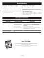
CALL US FIRST
For any questions about operating or maintaining your product,
call the Ryobi® Help Line!
Your product has been fully tested prior to shipment to ensure
your complete satisfaction.
PROBLEM POSSIBLE CAUSE SOLUTION
Line will not advance when us-
ing the auto-feed head
Line is welded to itself.
Not enough line on spool.
Line is worn too short.
Line is tangled on spool.
Lubricate with silicone spray.
Install more line. Refer to Line Replacement earlier in
this manual.
Pull line while pressing button.
Remove line from spool and rewind. Refer to Line
Replacement earlier in this manual.
Grass wraps around boom
housing and string head
Cutting tall grass at ground
level.
Cut tall grass from the top down to prevent wrapping.

10 — English
WARRANTY
LIMITED WARRANTY STATEMENT
Techtronic Industries North America, Inc., warrants to the
original retail purchaser that this RYOBI® brand outdoor
product is free from defect in material and workmanship
and agrees to repair or replace, at Techtronic Industries
North America, Inc.’s, discretion, any defective product
free of charge within these time periods from the date of
purchase.
Five years if the product is used for personal, family or
household use;
90 days, if used for any other purpose, such as
commercial or rental.
This warranty extends to the original retail purchaser
only and commences on the date of the original retail
purchase.
Any part of this product found in the reasonable judgment
of Techtronic Industries North America, Inc. to be defective
in material or workmanship will be repaired or replaced
without charge for parts and labor by an authorized service
center for RYOBI® brand outdoor products (Authorized
Ryobi Service Center).
The product, including any defective part, must be returned
to an authorized Ryobi service center within the warranty
period. The expense of delivering the product to the service
center for warranty work and the expense of returning it
back to the owner after repair or replacement will be paid
by the owner. Techtronic Industries North America, Inc.’s,
responsibility in respect to claims is limited to making the
required repairs or replacements and no claim of breach of
warranty shall be cause for cancellation or rescission of the
contract of sale of any RYOBI® brand outdoor product. Proof
of purchase will be required by the dealer to substantiate
any warranty claim. All warranty work must be performed
by an authorized service dealer.
This warranty is limited to ninety (90) days from the date
of original retail purchase for any RYOBI® brand outdoor
product that is used for rental or commercial purposes, or
any other income-producing purpose.
This warranty does not cover any product that has been
subject to misuse, neglect, negligence, or accident, or that
has been operated in any way contrary to the operating
instructions as specified in this operator’s manual. This
warranty does not apply to any damage to the product that
is the result of improper maintenance or to any product
that has been altered or modified. The warranty does not
extend to repairs made necessary by normal wear or by the
use of parts or accessories which are either incompatible
with the RYOBI® brand outdoor product or adversely affect
its operation, performance, or durability. In addition, this
warranty does not cover:
A. Tune-ups – Spark Plugs, Carburetor, Carburetor
Adjustments, Ignition, Filters
B. Wear items – Bump Knobs, Outer Spools, Cutting
Lines, Inner Reels, Starter Pulleys, Starter Ropes, Drive
Belts, Tines, Felt Washers, Hitch Pins, Mulching Blades,
Blower Fans, Blower and Vacuum Tubes, Vacuum Bag
and Straps, Guide Bars, Saw Chains
Techtronic Industries North America, Inc., reserves the
right to change or improve the design of any RYOBI® brand
outdoor product without assuming any obligation to modify
any product previously manufactured.
ALL IMPLIED WARRANTIES ARE LIMITED IN DURATION
TO THE STATED WARRANTY PERIOD. ACCORDINGLY,
ANY SUCH IMPLIED WARRANTIES INCLUDING
MERCHANTABILITY, FITNESS FOR A PARTICULAR
PURPOSE, OR OTHERWISE, ARE DISCLAIMED IN
THEIR ENTIRETY AFTER THE EXPIRATION OF THE
APPROPRIATE FIVE-YEAR OR NINETY-DAY WARRANTY
PERIOD. TECHTRONIC INDUSTRIES NORTH AMERICA,
INC.’S, OBLIGATION UNDER THIS WARRANTY IS
STRICTLY AND EXCLUSIVELY LIMITED TO THE
REPAIR OR REPLACEMENT OF DEFECTIVE PARTS
AND TECHTRONIC INDUSTRIES NORTH AMERICA,
INC., DOES NOT ASSUME OR AUTHORIZE ANYONE
TO ASSUME FOR THEM ANY OTHER OBLIGATION.
SOME STATES DO NOT ALLOW LIMITATIONS ON HOW
LONG AN IMPLIED WARRANTY LASTS, SO THE ABOVE
LIMITATION MAY NOT APPLY TO YOU. TECHTRONIC
INDUSTRIES NORTH AMERICA, INC., ASSUMES NO
RESPONSIBILITY FOR INCIDENTAL, CONSEQUENTIAL,
OR OTHER DAMAGES INCLUDING, BUT NOT LIMITED
TO, EXPENSE OF RETURNING THE PRODUCT TO AN
AUTHORIZED RYOBI SERVICE CENTER AND EXPENSE
OF DELIVERING IT BACK TO THE OWNER, MECHANIC’S
TRAVEL TIME, TELEPHONE OR TELEGRAM CHARGES,
RENTAL OF A LIKE PRODUCT DURING THE TIME
WARRANTY SERVICE IS BEING PERFORMED, TRAVEL,
LOSS OR DAMAGE TO PERSONAL PROPERTY, LOSS
OF REVENUE, LOSS OF USE OF THE PRODUCT, LOSS
OF TIME, OR INCONVENIENCE. SOME STATES DO NOT
ALLOW THE EXCLUSION OR LIMITATION OF INCIDENTAL
OR CONSEQUENTIAL DAMAGES, SO THE ABOVE
LIMITATION OR EXCLUSION MAY NOT APPLY TO YOU.
This warranty gives you specific legal rights, and you may
also have other rights which vary from state to state.
This warranty applies to all RYOBI® brand outdoor products
manufactured by or for Techtronic Industries North America,
Inc., and sold in the United States and Canada.
To locate your nearest Authorized Ryobi Service Center,
dial 1-800-860-4050.
Page is loading ...
Page is loading ...
Page is loading ...
Page is loading ...
Page is loading ...
Page is loading ...
Page is loading ...
Page is loading ...
Page is loading ...
Page is loading ...
Page is loading ...
Page is loading ...
Page is loading ...
Page is loading ...
Page is loading ...
Page is loading ...
Page is loading ...

990000799
4-25-14 (REV:03)
TECHTRONIC INDUSTRIES NORTH AMERICA, INC.
1428 Pearman Dairy Road, Anderson, SC 29625 USA
1-800-860-4050 • www.ryobitools.com
A subsidiary of Techtronic Industries Co., Ltd. • OTC:TTNDY
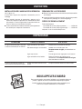
• PARTS AND SERVICE
Prior to requesting service or purchasing replacement parts, please obtain your model
and serial number from the product data plate.
• MODEL NO.
______________________SERIAL NO. __________________________
• HOW TO OBTAIN REPLACEMENT PARTS:
Replacement parts can be purchased online at www.ryobitools.com or by calling
1-800-860-4050. Replacement parts can also be obtained at one of our Authorized
Service Centers.
• HOW TO LOCATE AN AUTHORIZED SERVICE CENTER:
Authorized Service Centers can be located online at www.ryobitools.com or by call-
ing 1-800-860-4050.
• HOW TO OBTAIN CUSTOMER OR TECHNICAL SUPPORT:
To obtain Customer or Technical Support please contact us at 1-800-860-4050.
• PIÈCES ET SERVICE
Avant de faire la demande de service ou l’achat de pièces de remplacement, veuillez
obtenir le numéro de série du modèle à partir de la plaque de données du produit.
• NUMÉRO DE MODÈLE
____________NUMÉRO DE SÉRIE ___________________
• COMMENT OBTENIR LES PIÈCES DE REMPLACEMENT :
Les pièces de remplacement peuvent être achetées en ligne sur le site
www.ryobitools.com ou par téléphone au 1-800-860-4050. Les pièces de remplacement
peuvent être obtenues à un de nos centres de service autorisés.
• COMMENT TROUVER UN CENTRE DE SERVICE AUTORISÉ :
Les centres de service autorisés peuvent être localisés en ligne au www.ryobitools.
com ou en téléphonant au 1-800-860-4050.
• COMMENT OBTENIR DE L’AIDE EN CONTACTANT LE SERVICE À LA
CLIENTÈLE :
Pour contacter le service à la clientèle pour une question technique ou pour tout autre
renseignement, veuillez nous téléphoner au 1-800-860-4050.
• PIEZAS DE REPUESTO Y SERVICIO
Antes de solicitar servicio técnico o comprar piezas de repuesto, obtenga su modelo
y número de serie de la placa de datos del producto.
• NÚMERO DE MODELO
____________NÚMERO DE SERIE ___________________
• CÓMO OBTENER PIEZAS DE REPUESTO:
Las piezas de repuesto se pueden comprar en nuestro sitio en la red mundial, en la
dirección www.ryobitools.com o llamando al 1-800-860-4050. Las piezas de repuesto
también se pueden obtener en uno de nuestros Centros de Servicio Autorizados.
• CÓMO LOCALIZAR UN CENTRO DE SERVICIO AUTORIZADO:
Puede encontrar los Centros de Servicio Autorizados visitando nuestro sitio en la red
mundial, en la dirección www.ryobitools.com or by calling 1-800-860-4050.
• CÓMO OBTENER SERVICIO O ASISTENCIA TÉCNICA AL CONSUMIDOR:
Para obtener Servicio o Asistencia Técnica al Consumidor, sírvase comunicarse con
nosotros llamando al 1-800-860-4050.
OPERATOR’S MANUAL
MANUEL D’UTILISATION / MANUAL DEL OPERADOR
STRAIGHT SHAFT TRIMMER ATTACHMENT
ARBRE DROIT ACCESSOIRE TAILLE-BORDURES
ACCESORIO PARA RECORTAR DE EJE RECTO
RY15523A
CALIFORNIA PROPOSITION 65
WARNING:
This product and substances that may
become airborne from its use may con-
tain chemicals, including lead, known to
the State of California to cause cancer,
birth defects, or other reproductive harm.
Wash hands after handling.
RYOBI is a registered trademark of Ryobi
Limited and is used pursuant to a license
granted by Ryobi Limited.
RYOBI est une marque déposée de Ryobi
Limited et est utilisée en vertu d’une licence
accordée par Ryobi Limited.
RYOBI es una marca registrada de Ryobi
Limited y se utiliza conforme a una licencia
otorgada por Ryobi Limited.
PROPOSITION 65 DE L’ÉTAT
DE CALIFORNIE
AVERTISSEMENT :
Ce produit et les autres substances
rejetées dans l’air suite à son utilisation
peuvent contenir des produits chimiques,
notamment du plomb qui, selon l’État de
la Californie, peuvent causer le cancer,
des anomalies congénitales et d’autres
dommages au système reproducteur.
Bien se laver les mains après toute
manipulation.
CALIFORNIA - PROPUESTA
DE LEY NÚM. 65
ADVERTENCIA:
Este producto y las sustancias que
puedan llegar a ser aerotransportadas
por su uso pueden contener
sustancias químicas (incluido el plomo)
reconocidas por el estado de California
como causantes de cáncer, defectos
congénitos y otras afecciones del
aparato reproductor. Lávese las manos
después de utilizar el aparato.
Page is loading ...
Page is loading ...
Page is loading ...
Page is loading ...
Page is loading ...
Page is loading ...
Page is loading ...
Page is loading ...
Page is loading ...
Page is loading ...
Page is loading ...
Page is loading ...
Page is loading ...
Page is loading ...
Page is loading ...
Page is loading ...
Page is loading ...
Page is loading ...
Page is loading ...
Page is loading ...
Page is loading ...
Page is loading ...
Page is loading ...
Page is loading ...
Page is loading ...
Page is loading ...
Page is loading ...
Page is loading ...
Page is loading ...
Page is loading ...
-
 1
1
-
 2
2
-
 3
3
-
 4
4
-
 5
5
-
 6
6
-
 7
7
-
 8
8
-
 9
9
-
 10
10
-
 11
11
-
 12
12
-
 13
13
-
 14
14
-
 15
15
-
 16
16
-
 17
17
-
 18
18
-
 19
19
-
 20
20
-
 21
21
-
 22
22
-
 23
23
-
 24
24
-
 25
25
-
 26
26
-
 27
27
-
 28
28
-
 29
29
-
 30
30
-
 31
31
-
 32
32
-
 33
33
-
 34
34
-
 35
35
-
 36
36
-
 37
37
-
 38
38
-
 39
39
-
 40
40
-
 41
41
-
 42
42
-
 43
43
-
 44
44
-
 45
45
-
 46
46
-
 47
47
-
 48
48
-
 49
49
-
 50
50
-
 51
51
-
 52
52
-
 53
53
-
 54
54
-
 55
55
-
 56
56
-
 57
57
-
 58
58
-
 59
59
-
 60
60
-
 61
61
-
 62
62
-
 63
63
-
 64
64
-
 65
65
-
 66
66
-
 67
67
-
 68
68
-
 69
69
-
 70
70
-
 71
71
-
 72
72
-
 73
73
-
 74
74
-
 75
75
-
 76
76
-
 77
77
-
 78
78
-
 79
79
-
 80
80
-
 81
81
-
 82
82
-
 83
83
-
 84
84
-
 85
85
-
 86
86
-
 87
87
-
 88
88
-
 89
89
-
 90
90
-
 91
91


Ask a question and I''ll find the answer in the document
Finding information in a document is now easier with AI
in other languages
- français: Ryobi RY40230-4X Mode d'emploi
- español: Ryobi RY40230-4X Guía del usuario

