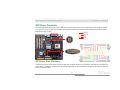
AOpen MX46LS-533V Online Manual
- Category
- Audio cards
- Type
- Online Manual
This manual is also suitable for

1
M
M
X
X
4
4
6
6
L
L
S
S
-
-
V
V
/
/
M
M
X
X
4
4
6
6
L
L
S
S
-
-
5
5
3
3
3
3
V
V
O
O
n
n
l
l
i
i
n
n
e
e
M
M
a
a
n
n
u
u
a
a
l
l
Overview
Hardware
Installation
Drivers &
Utilities
AWARD
BIOS Setup
Glossary
Troubleshooting &
Technical Support
MX46LS-V / MX46LS-533V
DOC. NO.: MX46LSV-OL-E0301B

2
M
M
X
X
4
4
6
6
L
L
S
S
-
-
V
V
/
/
M
M
X
X
4
4
6
6
L
L
S
S
-
-
5
5
3
3
3
3
V
V
O
O
n
n
l
l
i
i
n
n
e
e
M
M
a
a
n
n
u
u
a
a
l
l
W
W
h
h
a
a
t
t
’
’
s
s
i
i
n
n
t
t
h
h
i
i
s
s
m
m
a
a
n
n
u
u
a
a
l
l
MX46LS-V / MX46LS-533V.............................................................................................................................1
What’s in this manual................................................................................................................................................................ 2
You Must Notice........................................................................................................................................................................ 8
Before You Start........................................................................................................................................................................ 9
Overview................................................................................................................................................................................. 10
Feature Highlight .....................................................................................................................................................................11
Quick Installation Procedure ................................................................................................................................................... 15
Motherboard Map ................................................................................................................................................................... 16
Block Diagram ........................................................................................................................................................................ 17
Hardware Installation ............................................................................................................................18
About “User Upgrade Optional” and “Manufacture Upgrade Optional”… ................................................................................. 19
CPU Installation...................................................................................................................................................................... 20
Enlarged Aluminum Heatsink .................................................................................................................................................. 23
Full-range Adjustable CPU Core Voltage................................................................................................................................. 24
CPU and System Fan Connectors (with H/W Monitoring) ..................................................................................................... 26
DIMM Sockets ........................................................................................................................................................................ 27
Front Panel Connector............................................................................................................................................................ 29
ATX Power Connector............................................................................................................................................................. 30

3
M
M
X
X
4
4
6
6
L
L
S
S
-
-
V
V
/
/
M
M
X
X
4
4
6
6
L
L
S
S
-
-
5
5
3
3
3
3
V
V
O
O
n
n
l
l
i
i
n
n
e
e
M
M
a
a
n
n
u
u
a
a
l
l
AC Power Auto Recovery........................................................................................................................................................ 30
IDE and Floppy Connector...................................................................................................................................................... 31
ATA133 Supported.................................................................................................................................................................. 33
IrDA Connector ....................................................................................................................................................................... 34
AGP (Accelerated Graphic Port) Expansion Slot..................................................................................................................... 35
WOL (Wake on LAN) .............................................................................................................................................................. 36
Support 10/100 Mbps LAN onboard ........................................................................................................................................ 38
CNR (Communication and Network Riser) Expansion Slot...................................................................................................... 39
Support Three USB2.0 Channels (Six Ports)........................................................................................................................... 40
Color Coded Back Panel......................................................................................................................................................... 41
Chassis Intrusion Connector................................................................................................................................................... 42
CD Audio Connector ............................................................................................................................................................... 43
MODEM-IN Connector............................................................................................................................................................ 44
COM2 Connector.................................................................................................................................................................... 45
Front Audio Connector............................................................................................................................................................ 46
S/PDIF (Sony/Philips Digital Interface) Connector................................................................................................................... 47
JP14 Clear CMOS Data.......................................................................................................................................................... 48
JP28 USB Keyboard/Mouse Wake-up Enable/Disable Jumper ............................................................................................... 49
Battery-less and Long Life Design .......................................................................................................................................... 51

4
M
M
X
X
4
4
6
6
L
L
S
S
-
-
V
V
/
/
M
M
X
X
4
4
6
6
L
L
S
S
-
-
5
5
3
3
3
3
V
V
O
O
n
n
l
l
i
i
n
n
e
e
M
M
a
a
n
n
u
u
a
a
l
l
Over-current Protection........................................................................................................................................................... 52
Resetable Fuse....................................................................................................................................................................... 53
Low ESR Capacitor................................................................................................................................................................. 54
Phoenix-AWARD BIOS ............................................................................................................................56
About BIOS Function Description… ........................................................................................................................................ 57
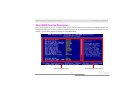
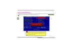
How To Use Phoenix-Award™ BIOS Setup Program .............................................................................................................. 58
How To Enter BIOS Setup....................................................................................................................................................... 60
BIOS Upgrade under Windows environment........................................................................................................................... 61
Driver and Utility....................................................................................................................................63
Auto-run Menu from Bonus CD ............................................................................................................................................... 63
Install IDE Driver..................................................................................................................................................................... 64
Installing AGP Driver............................................................................................................................................................... 65
Installing VGA Driver............................................................................................................................................................... 66
Install USB2.0 Driver............................................................................................................................................................... 67
Installing LAN Driver ............................................................................................................................................................... 68
Installing Onboard Sound Driver ............................................................................................................................................. 69
AOConfig Utility ...................................................................................................................................................................... 70
Installing Hardware Monitoring Utility ...................................................................................................................................... 72
Glossary .................................................................................................................................................73

5
M
M
X
X
4
4
6
6
L
L
S
S
-
-
V
V
/
/
M
M
X
X
4
4
6
6
L
L
S
S
-
-
5
5
3
3
3
3
V
V
O
O
n
n
l
l
i
i
n
n
e
e
M
M
a
a
n
n
u
u
a
a
l
l
AC97 CODEC......................................................................................................................................................................... 73
ACPI (Advanced Configuration & Power Interface) ................................................................................................................. 73
ACR (Advanced Communication Riser) .................................................................................................................................. 73
AGP (Accelerated Graphic Port) ............................................................................................................................................. 74
AMR (Audio/Modem Riser) ..................................................................................................................................................... 74
ATA (AT Attachment)............................................................................................................................................................... 74
BIOS (Basic Input/Output System).......................................................................................................................................... 75
Bluetooth ................................................................................................................................................................................ 75
CNR (Communication and Networking Riser) ......................................................................................................................... 76
DDR (Double Data Rate) RAM................................................................................................................................................ 76
ECC (Error Checking and Correction) ..................................................................................................................................... 76
EEPROM (Electronic Erasable Programmable ROM) ............................................................................................................. 77
EPROM (Erasable Programmable ROM)................................................................................................................................ 77
EV6 Bus.................................................................................................................................................................................. 77
FCC DoC (Declaration of Conformity)..................................................................................................................................... 77
FC-PGA (Flip Chip-Pin Grid Array).......................................................................................................................................... 78
FC-PGA2 (Flip Chip-Pin Grid Array)........................................................................................................................................ 78
Flash ROM ............................................................................................................................................................................. 78
Hyper Threading..................................................................................................................................................................... 78

6
M
M
X
X
4
4
6
6
L
L
S
S
-
-
V
V
/
/
M
M
X
X
4
4
6
6
L
L
S
S
-
-
5
5
3
3
3
3
V
V
O
O
n
n
l
l
i
i
n
n
e
e
M
M
a
a
n
n
u
u
a
a
l
l
IEEE 1394 .............................................................................................................................................................................. 79
Parity Bit ................................................................................................................................................................................. 79
PCI (Peripheral Component Interface) Bus ............................................................................................................................. 80
PDF Format ............................................................................................................................................................................ 80
PnP (Plug and Play)................................................................................................................................................................ 80
POST (Power-On Self Test) .................................................................................................................................................... 80
PSB (Processor System Bus) Clock........................................................................................................................................ 81
RDRAM (Rambus Dynamic Random Access Memory) ........................................................................................................... 81
RIMM (Rambus Inline Memory Module).................................................................................................................................. 81
SDRAM (Synchronous DRAM) ............................................................................................................................................... 81
SATA (Serial ATA) ................................................................................................................................................................... 82
SMBus (System Management Bus) ........................................................................................................................................ 82
SPD (Serial Presence Detect)................................................................................................................................................. 82
USB 2.0 (Universal Serial Bus) ............................................................................................................................................... 82
VCM (Virtual Channel Memory) .............................................................................................................................................. 83
Wireless LAN – 802.11b.......................................................................................................................................................... 83
ZIP file .................................................................................................................................................................................... 83
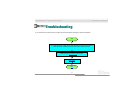
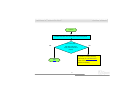
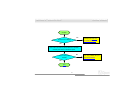
Troubleshooting .....................................................................................................................................84
Technical Support..................................................................................................................................88

7
M
M
X
X
4
4
6
6
L
L
S
S
-
-
V
V
/
/
M
M
X
X
4
4
6
6
L
L
S
S
-
-
5
5
3
3
3
3
V
V
O
O
n
n
l
l
i
i
n
n
e
e
M
M
a
a
n
n
u
u
a
a
l
l
Product Registration..............................................................................................................................91
How to Contact Us.................................................................................................................................92

8
M
M
X
X
4
4
6
6
L
L
S
S
-
-
V
V
/
/
M
M
X
X
4
4
6
6
L
L
S
S
-
-
5
5
3
3
3
3
V
V
O
O
n
n
l
l
i
i
n
n
e
e
M
M
a
a
n
n
u
u
a
a
l
l
Y
Y
o
o
u
u
M
M
u
u
s
s
t
t
N
N
o
o
t
t
i
i
c
c
e
e
Adobe, the Adobe logo, Acrobat is trademarks of Adobe Systems Incorporated.
AMD, the AMD logo, Athlon and Duron are trademarks of Advanced Micro Devices, Inc.
Intel, the Intel logo, Intel Celeron, Pentium II, Pentium III and Pentium 4 are trademarks of Intel Corporation.
Microsoft, Windows, and Windows logo are either registered trademarks or trademarks of Microsoft Corporation in the United States and/or
other countries.
All product and brand names used on this manual are used for identification purposes only and may be the registered trademarks of their
respective owners.
All of the specifications and information contained in this manual are subject to change without notice. AOpen reserves the right to revise
this publication and to make reasonable changes. AOpen assumes no responsibility for any errors or inaccuracies that may appear in this
manual, including the products and software described in it.
This documentation is protected by copyright law. All rights are reserved.
No part of this document may be used or reproduced in any form or by any means, or stored in a database or retrieval system
without prior written permission from AOpen Corporation.
Copyright
©
1996-2003, AOpen Inc. All Rights Reserved.

9
M
M
X
X
4
4
6
6
L
L
S
S
-
-
V
V
/
/
M
M
X
X
4
4
6
6
L
L
S
S
-
-
5
5
3
3
3
3
V
V
O
O
n
n
l
l
i
i
n
n
e
e
M
M
a
a
n
n
u
u
a
a
l
l
B
B
e
e
f
f
o
o
r
r
e
e
Y
Y
o
o
u
u
S
S
t
t
a
a
r
r
t
t
This Online Manual will introduce to the user how this product is installed. All useful information will be described in later chapters. Please
keep this manual carefully for future upgrades or system configuration changes. This Online Manual is saved in PDF format
, we
recommend using Adobe Acrobat Reader 4.0 for online viewing, it is included in Bonus CD
or you can get free download from Adobe web
site.
Although this Online Manual is optimized for screen viewing, it is still capable for hardcopy printing, you can print it by A4 paper size and set
2 pages per A4 sheet on your printer. To do so, choose File > Page Setup and follow the instruction of your printer driver.
Thanks for the help of saving our earth.

10
M
M
X
X
4
4
6
6
L
L
S
S
-
-
V
V
/
/
M
M
X
X
4
4
6
6
L
L
S
S
-
-
5
5
3
3
3
3
V
V
O
O
n
n
l
l
i
i
n
n
e
e
M
M
a
a
n
n
u
u
a
a
l
l
O
O
v
v
e
e
r
r
v
v
i
i
e
e
w
w
Thank you for choosing AOpen MX46LS-V / MX46LS-533V motherboard. MX46LS-V / MX46LS-533V is Intel
®
Socket 478 motherboard
(M/B) based on the micro-ATX form factor featuring the SIS 650GX chipset
(MX46LS-V) and the SIS 651 chipset. As high performance
chipset built in the M/B, MX46LS-V supports Intel
®
Socket 478 Pentium
®
4 (Willamette / Northwood) and 400MHz Front Side Bus (FSB)
clock. MX46LS-533V supports Intel
®
Socket 478 Pentium
®
4 (Willamette / Northwood) and 400MHz/533MHz Front Side Bus (FSB) clock. In
the AGP performance, it has one AGP slot and supports AGP
4X mode and pipelined spilt-transaction long burst transfer up to 1056MB/sec.
According to different customer’s requirements, MX46LS-V / MX46LS-533V supports PC100/PC133 SDRAM up to 1GB maximum. The
onboard IDE controller supports Ultra DMA
33/66/100/133 mode. More than that, on the strength of integrated SiS LAN controller with
Realtek PHY on board, which is a highly integrated Platform LAN Connect device, it provides 10/100M bps Ethernet for office and home
use. Six USB 2.0
ports are supported with a fancy speed of up to 480Mbps. Besides, MX46LS-V / MX46LS-533V has an AC97 CODEC
chipset onboard providing high performance and magic surround stereo sound to let people enjoy working with
it. Now, let’s enjoy all features from AOpen MX46LS-V / MX46LS-533V motherboard.

11
M
M
X
X
4
4
6
6
L
L
S
S
-
-
V
V
/
/
M
M
X
X
4
4
6
6
L
L
S
S
-
-
5
5
3
3
3
3
V
V
O
O
n
n
l
l
i
i
n
n
e
e
M
M
a
a
n
n
u
u
a
a
l
l
F
F
e
e
a
a
t
t
u
u
r
r
e
e
H
H
i
i
g
g
h
h
l
l
i
i
g
g
h
h
t
t
CPU
MX46LS-V supports Intel
®
Socket 478 Pentium
®
4 (Willamette / Northwood) 1.4GHz~2.8GHz+ with 400MHz Front Side Bus (FSB) designed
for Socket 478 technology and MX46LV-533V with 400MHz/533MHz Front Side Bus (FSB).
Chipset
MX46LS-V
This motherboard is equipped with SIS 650GX chipset. SiS 650GX chipset consists of host interface Controller and integrated high
performance SDRAM
Host system controller, which provides superior performance among CPU, SDRAM, and AGP buses. In coordination
with SiS 650GX, the SIS 962L chipset is integrated fast Ethernet/Home networking controller, Audio/Modem Controller with AC’97 interface
and advanced power management, which can strongly enhance the system performance.
MX46LS-533V
This motherboard is equipped with SIS 651 chipset. SIS 651 IGUI Host Memory Controller integrates a high performance host interface for
Intel Pentium 4 processor, a high performance 2D/3D Graphic Engine, a high performance memory controller and an AGP 4X interface.
SiS651 Host Interface features the AGTL & AGTL+ compliant bus driver technology with integrated on-die termination to support Intel
Pentium 4 series processors with FSB 100MHz and over clocking up to 133MHz. SiS651 also can support external AGP slot with AGP
1X/2X/4X capability and Fast Write Transactions.
The South Bridge SIS 962L MuTIOL Media I/O integrates one Universal Serial Bus 2.0 Host Controllers, the Audio Controller with AC97
Interface, three Universal Serial Bus 1.1 Host Controllers and the IDE Master/Slave controllers. The PCI to LPC bridge, I/O Advanced

12
M
M
X
X
4
4
6
6
L
L
S
S
-
-
V
V
/
/
M
M
X
X
4
4
6
6
L
L
S
S
-
-
5
5
3
3
3
3
V
V
O
O
n
n
l
l
i
i
n
n
e
e
M
M
a
a
n
n
u
u
a
a
l
l
Programmable Interrupt Controller, legacy system I/O and legacy power management functionalities are integrated as well. The SIS 961B
chipset integrated fast Ethernet/Home networking controller, Audio/Modem Controller with AC’97 interface and advanced power
management, which can strongly enhance the system performance.
Expansion Slots
Including three 32-bit/33MHz PCI, one AGP 1X/2X/4X slots. The PCI local bus throughput can be up to 132MB/s. The Accelerated Graphics
Port (AGP) specification provides a new level of video display sophistication and speed. The AGP video cards support data transfer rate up
to 1056MB/s. MX46LS-V / MX46LS-533V motherboard includes one AGP expansion slot for a bus mastering AGP graphic card. For AD
and SBA signaling, MX46LS-V / MX46LS-533V motherboard can support 4X mode. Of three PCI slots provided, all of them are master PCI
slots with arbitration and decoding for all integrated functions and LPC bus.
Memory
MX46LS-V / MX46LS-533V provides two 168-pin SDRAM SIMM sockets that support up to 1GB of PC100/PC133 compliant SDRAM
(Synchronous Dynamic Random Access Memory).
Watch Dog Timer
Includes AOpen “Watch Dog Timer” function that can auto-reset system in 4.8 seconds when you fail to system overclocking.
1MHz Stepping CPU Frequency Adjustment
Provides “1MHz Stepping CPU Frequency Adjustment” function in the BIOS. This magic function allows you to adjust CPU FSB frequency
from 100~248MHz by 1MHz stepping adjustment, and helps your system get maximum performance.

13
M
M
X
X
4
4
6
6
L
L
S
S
-
-
V
V
/
/
M
M
X
X
4
4
6
6
L
L
S
S
-
-
5
5
3
3
3
3
V
V
O
O
n
n
l
l
i
i
n
n
e
e
M
M
a
a
n
n
u
u
a
a
l
l
LAN Port
On the strength of integrated SiS LAN controller with Realtek PHY on board, which is a highly integrated Platform LAN Connect device, it
provides 10/100 Mbps Ethernet for office and home use.
Ultra DMA 33/66/100/133 Bus Mater IDE
Comes with an on-board PCI Bus Master IDE controller with two connectors that support four IDE devices in two channels, supports Ultra
DMA 33/66/100/133, PIO Modes 3 and 4 and Bus Master IDE DMA Mode 6, and supports Enhanced IDE devices.
On-board AC’97 Sound
MX46LS-V / MX46LS-533V uses RealTek AC97 sound chip. This on-board audio includes a complete audio recording and playback
system.
3 USB2.0 Channels (6 Ports)
Provides 3 USB2.0 channels (6 ports) for USB interface devices, such as mouse, keyboard, modem, scanner, etc.
S/PDIF Connectors
S/PDIF (Sony/Philips Digital Interface) is the newest audio transfer file format, which provides impressive quality through optical fiber and
allows you to enjoy digital audio instead of analog audio.

14
M
M
X
X
4
4
6
6
L
L
S
S
-
-
V
V
/
/
M
M
X
X
4
4
6
6
L
L
S
S
-
-
5
5
3
3
3
3
V
V
O
O
n
n
l
l
i
i
n
n
e
e
M
M
a
a
n
n
u
u
a
a
l
l
Power Management/Plug and Play
Supports the power management function that confirms to the power-saving standards of the U.S. Environmental Protection Agency (EPA)
Energy Star program. It also offers Plug-and-Play
, which helps save users from configuration problems, thus making the system much
user-friendlier.
Hardware Monitoring Management
Supports CPU or system fans status, temperature and voltage monitoring and alert, through the on-board hardware monitor module.
Enhanced ACPI
Fully implement the ACPI standard for Windows
®
98/ME/2000 series compatibility, and supports Soft-Off, STR (Suspend to RAM, S3), STD
(Suspend to Disk, S4) features.
Super Multi-I/O
Provides two high-speed UART compatible serial ports and one parallel port with EPP and ECP capabilities. UART can also be directed
from COM1 to the Infrared Module for the wireless connections.

15
M
M
X
X
4
4
6
6
L
L
S
S
-
-
V
V
/
/
M
M
X
X
4
4
6
6
L
L
S
S
-
-
5
5
3
3
3
3
V
V
O
O
n
n
l
l
i
i
n
n
e
e
M
M
a
a
n
n
u
u
a
a
l
l
Q
Q
u
u
i
i
c
c
k
k
I
I
n
n
s
s
t
t
a
a
l
l
l
l
a
a
t
t
i
i
o
o
n
n
P
P
r
r
o
o
c
c
e
e
d
d
u
u
r
r
e
e
This page gives you a quick procedure on how to install your system. Follow each step accordingly.
1. Installing CPU and Fan
2. Installing System Memory (DIMM)
3. Connecting Front Panel Cable
4. Connecting IDE and Floppy Cable
5. Connecting ATX Power Cable
6. Connecting Back Panel Cable
7. Power-on and Load BIOS Setup Default
8. Setting CPU Frequency
9. Reboot
10. Installing Operating System (such as Windows 98)
11. Installing Driver and Utility

16
M
M
X
X
4
4
6
6
L
L
S
S
-
-
V
V
/
/
M
M
X
X
4
4
6
6
L
L
S
S
-
-
5
5
3
3
3
3
V
V
O
O
n
n
l
l
i
i
n
n
e
e
M
M
a
a
n
n
u
u
a
a
l
l
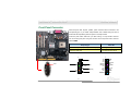
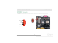
Case Open Connecto
r
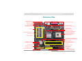
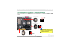
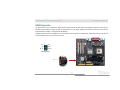
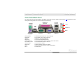
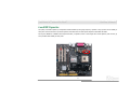
Motherboard Map
PC99 Colored Back Panel
JP14 CMOS Clear Jumpe
r
Realtek Ethernet PH
Y
COM2 Connecto
r
Front Audio Connecto
r
IrDA Connecto
r
Front Panel Connecto
r
SYSFAN2 Connecto
r
A
TA 100/133 IDE2 Connecto
r
FDD Connector
168-pin SIMMx2 supports
PC100/133 SDRAM maximum
up to 1GB
A
TX Power Connector
SIS 650GX/962L Chipset (MX46LS-V)
SIS 651/962L Chipset (MX46LS-533V)
478-pin CPU socket (Willamette/
Northwood) with Voltage and
Frequency Auto-detection that
supports Intel
®
Pentium
®
4
1.4~2.8GHz+ CPU
A
GP 4x Ex
p
ansion Slot
32-bit PCI Expansion Slot x3
4-pin 12V. ATX Power Connector
Low ESR Capacitors
3
rd
USB2.0 channels
WOL Connecto
r
CD-IN Connecto
r
SYSFAN3 Connecto
r
Flash ROM BIOS
CPUFAN1 connecto
r
S/PDIF Connecto
r
MODEM-IN Connecto
r
AC’97 CODEC
A
TA 100/133 IDE1 Connecto
r
CNR Slo
t
ITE IT8705

17
M
M
X
X
4
4
6
6
L
L
S
S
-
-
V
V
/
/
M
M
X
X
4
4
6
6
L
L
S
S
-
-
5
5
3
3
3
3
V
V
O
O
n
n
l
l
i
i
n
n
e
e
M
M
a
a
n
n
u
u
a
a
l
l
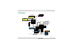
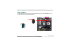
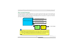
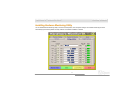
MX46LS-V: SIS
650GX
MX46LS-533V:
SIS 651
Socket 478
Intel Pentium 4
CPU(Willamette
/Northwood)
MX46LS-V: 400MHz
System Bus
SIMM Socket x2
AGP 4X Slot
SIS 962L
Serial Port x2
1
st
USB Channel
USB2.0
port x6
32-bit PCI Slot x3
Parallel Port
IDE Drive x4
ATA
66/100/133
PC100/PC133 SDRAM
Up to 1GB
Primary
Channel
Secondary
Channel
2Mbit Flash EEPROM
PCI Bus
ITE
IT8705F
Floppy Disk Drive x2
RealTek
AC97
CODEC
Realtek
LAN PHY
LAN connect Component
3
rd
USB Channel
2
nd
USB Channel
MX46LS-533V: 400/533MHz
System Bus
B
B
l
l
o
o
c
c
k
k
D
D
i
i
a
a
g
g
r
r
a
a
m
m

18
M
M
X
X
4
4
6
6
L
L
S
S
-
-
V
V
/
/
M
M
X
X
4
4
6
6
L
L
S
S
-
-
5
5
3
3
3
3
V
V
O
O
n
n
l
l
i
i
n
n
e
e
M
M
a
a
n
n
u
u
a
a
l
l
H
H
a
a
r
r
d
d
w
w
a
a
r
r
e
e
I
I
n
n
s
s
t
t
a
a
l
l
l
l
a
a
t
t
i
i
o
o
n
n
This chapter describes jumpers, connectors and hardware devices of this motherboard.
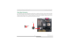
Note: Electrostatic discharge (ESD) can damage your processor, disk drives, expansion boards, and other
components. Always observe the following precautions before you install a system component.
1. Do not remove a component from its protective packaging until you are ready to install it.
2. Wear a wrist ground strap and attach it to a metal part of the system unit before handling a component. If
a wrist strap is not available, maintain contact with the system unit throughout any procedure requiring
ESD protection.

19
M
M
X
X
4
4
6
6
L
L
S
S
-
-
V
V
/
/
M
M
X
X
4
4
6
6
L
L
S
S
-
-
5
5
3
3
3
3
V
V
O
O
n
n
l
l
i
i
n
n
e
e
M
M
a
a
n
n
u
u
a
a
l
l
A
A
b
b
o
o
u
u
t
t
“
“
U
U
s
s
e
e
r
r
U
U
p
p
g
g
r
r
a
a
d
d
e
e
O
O
p
p
t
t
i
i
o
o
n
n
a
a
l
l
”
”
a
a
n
n
d
d
“
“
M
M
a
a
n
n
u
u
f
f
a
a
c
c
t
t
u
u
r
r
e
e
U
U
p
p
g
g
r
r
a
a
d
d
e
e
O
O
p
p
t
t
i
i
o
o
n
n
a
a
l
l
”
”
…
…
When you read this online manual and start to assemble your computer system, you may notice that some of the functions are marked as
“User Upgrade Optional” or “Manufacture Upgrade Optional”. Although all of AOpen’s motherboards have included many amazing and
powerful features, sometimes not every user is familiar with these powerful features. As a result of this we define features that can be
upgraded by users as “User Upgrade Optional”. You can upgrade these functions by purchasing additional devices. As for functions that
cannot be upgraded by users, we define them as “Manufacture Upgrade Optional”. If need be, you can contact our local distributors or
resellers to purchase “Manufacture Upgrade Optional” components, and again you are also welcome to visit our official website at
HTTP://english.aopen.com.tw
for detail information.

20
M
M
X
X
4
4
6
6
L
L
S
S
-
-
V
V
/
/
M
M
X
X
4
4
6
6
L
L
S
S
-
-
5
5
3
3
3
3
V
V
O
O
n
n
l
l
i
i
n
n
e
e
M
M
a
a
n
n
u
u
a
a
l
l
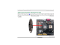
C
C
P
P
U
U
I
I
n
n
s
s
t
t
a
a
l
l
l
l
a
a
t
t
i
i
o
o
n
n
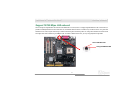
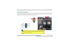
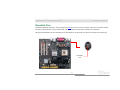
This motherboard supports Intel
®
Pentium 4 Socket 478 series CPU (Willamette / Northwood). Be careful of CPU orientation when you plug
it into CPU socket.
Note: Those pictures are for example only; they may not look the same with the motherboard you purchased.
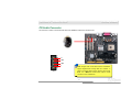
2. Locate Pin 1 in the socket and look for mark on the CPU upper interface.
Match Pin 1 and cut edge, then insert the CPU into the socket.
CPU pin 1 and
cut edge
CPU socket
Lever
1. Pull up the CPU socket lever and
up to 90-degree angle.
CPU cut edge
Page is loading ...
Page is loading ...
Page is loading ...
Page is loading ...
Page is loading ...
Page is loading ...
Page is loading ...
Page is loading ...
Page is loading ...
Page is loading ...
Page is loading ...
Page is loading ...
Page is loading ...
Page is loading ...
Page is loading ...
Page is loading ...
Page is loading ...
Page is loading ...
Page is loading ...
Page is loading ...
Page is loading ...
Page is loading ...
Page is loading ...
Page is loading ...
Page is loading ...
Page is loading ...
Page is loading ...
Page is loading ...
Page is loading ...
Page is loading ...
Page is loading ...
Page is loading ...
Page is loading ...
Page is loading ...
Page is loading ...
Page is loading ...
Page is loading ...
Page is loading ...
Page is loading ...
Page is loading ...
Page is loading ...
Page is loading ...
Page is loading ...
Page is loading ...
Page is loading ...
Page is loading ...
Page is loading ...
Page is loading ...
Page is loading ...
Page is loading ...
Page is loading ...
Page is loading ...
Page is loading ...
Page is loading ...
Page is loading ...
Page is loading ...
Page is loading ...
Page is loading ...
Page is loading ...
Page is loading ...
Page is loading ...
Page is loading ...
Page is loading ...
Page is loading ...
Page is loading ...
Page is loading ...
Page is loading ...
Page is loading ...
Page is loading ...
Page is loading ...
Page is loading ...
Page is loading ...
-
 1
1
-
 2
2
-
 3
3
-
 4
4
-
 5
5
-
 6
6
-
 7
7
-
 8
8
-
 9
9
-
 10
10
-
 11
11
-
 12
12
-
 13
13
-
 14
14
-
 15
15
-
 16
16
-
 17
17
-
 18
18
-
 19
19
-
 20
20
-
 21
21
-
 22
22
-
 23
23
-
 24
24
-
 25
25
-
 26
26
-
 27
27
-
 28
28
-
 29
29
-
 30
30
-
 31
31
-
 32
32
-
 33
33
-
 34
34
-
 35
35
-
 36
36
-
 37
37
-
 38
38
-
 39
39
-
 40
40
-
 41
41
-
 42
42
-
 43
43
-
 44
44
-
 45
45
-
 46
46
-
 47
47
-
 48
48
-
 49
49
-
 50
50
-
 51
51
-
 52
52
-
 53
53
-
 54
54
-
 55
55
-
 56
56
-
 57
57
-
 58
58
-
 59
59
-
 60
60
-
 61
61
-
 62
62
-
 63
63
-
 64
64
-
 65
65
-
 66
66
-
 67
67
-
 68
68
-
 69
69
-
 70
70
-
 71
71
-
 72
72
-
 73
73
-
 74
74
-
 75
75
-
 76
76
-
 77
77
-
 78
78
-
 79
79
-
 80
80
-
 81
81
-
 82
82
-
 83
83
-
 84
84
-
 85
85
-
 86
86
-
 87
87
-
 88
88
-
 89
89
-
 90
90
-
 91
91
-
 92
92


AOpen MX46LS-533V Online Manual
- Category
- Audio cards
- Type
- Online Manual
- This manual is also suitable for
Ask a question and I''ll find the answer in the document
Finding information in a document is now easier with AI
Related papers
-
AOpen AX4BS Pro Online Manual
-
-
-
-
-
-
-
-
-
