Da-Lite Da-Tex (Rear), 152 x 203 cm User manual
- Category
- Projection screens
- Type
- User manual
This manual is also suitable for
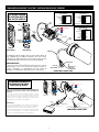
Da-Lite Da-Tex (Rear), 152 x 203 cm is a high-quality projection screen that is perfect for use in a variety of settings, including homes, offices, and schools. The screen is made of a durable, matte white material that provides a bright, clear image with wide viewing angles. It is also easy to clean and maintain.
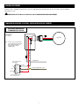
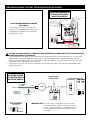
One of the best features of the Da-Lite Da-Tex (Rear), 152 x 203 cm is its rear projection design. This means that the projector can be placed behind the screen, which can save space and make it easier to set up. The screen also has a black backing that helps to prevent light from passing through the screen, which can improve image quality.
Da-Lite Da-Tex (Rear), 152 x 203 cm is a high-quality projection screen that is perfect for use in a variety of settings, including homes, offices, and schools. The screen is made of a durable, matte white material that provides a bright, clear image with wide viewing angles. It is also easy to clean and maintain.
One of the best features of the Da-Lite Da-Tex (Rear), 152 x 203 cm is its rear projection design. This means that the projector can be placed behind the screen, which can save space and make it easier to set up. The screen also has a black backing that helps to prevent light from passing through the screen, which can improve image quality.


-
 1
1
-
 2
2
-
 3
3
-
 4
4
-
 5
5
-
 6
6
-
 7
7
-
 8
8


Da-Lite Da-Tex (Rear), 152 x 203 cm User manual
- Category
- Projection screens
- Type
- User manual
- This manual is also suitable for
Da-Lite Da-Tex (Rear), 152 x 203 cm is a high-quality projection screen that is perfect for use in a variety of settings, including homes, offices, and schools. The screen is made of a durable, matte white material that provides a bright, clear image with wide viewing angles. It is also easy to clean and maintain.
One of the best features of the Da-Lite Da-Tex (Rear), 152 x 203 cm is its rear projection design. This means that the projector can be placed behind the screen, which can save space and make it easier to set up. The screen also has a black backing that helps to prevent light from passing through the screen, which can improve image quality.
Ask a question and I''ll find the answer in the document
Finding information in a document is now easier with AI
Related papers
-
Da-Lite Advantage Electrol 60" x 96" User manual
-
-
Da-Lite 85398LS User manual
-
-
Da-Lite Contour Electrol 87" x 116" Installation guide
-
-
-
-
Da-Lite Cosmopolitan Electrol, 145 x 196 cm Installation guide
-
Da-Lite 84968L User manual
Other documents
-
Projecta Tabscreen Electrol, High Contrast Cinema Vision Installation guide
-
Dragonfly DF-SL-120-MW Installation guide
-
Draper 121171 Datasheet
-
CableWholesale 8101-64201 Datasheet
-
-
Infocus SC-PUW-73 Datasheet
-
-
-
-
 In-Lite in-lite BIG SCOPE TONE 12V Outdoor Spotlight User manual
