
©2009 Sony Corporation
4-130-029-13(1)
Home Theatre
System
Operating Instructions
HT-SF100
HT-SS100

2
GB
To reduce the risk of fire or electric
shock, do not expose this apparatus to
rain or moisture.
To reduce the risk of fire, do not cover the
ventilation opening of the apparatus with
newspapers, tablecloths, curtain, etc.
Do not place the naked flame sources such as lighted
candles on the apparatus.
To reduce the risk of fire or electric shock, do not
expose this apparatus to dripping or splashing, and
do not place objects filled with liquids, such as
vases, on the apparatus.
Do not install the appliance in a confined space, such
as a bookcase or built-in cabinet.
As the main plug is used to disconnect the unit from
the mains, connect the unit to an easily accessible
AC outlet. Should you notice an abnormality in the
unit, disconnect the main plug from the AC outlet
immediately.
Do not expose batteries or apparatus with battery-
installed to excessive heat such as sunshine, fire or
the like.
To prevent injury, this apparatus must be securely
attached to the floor/wall in accordance with the
installation instructions.
For customers in Europe
Disposal of Old Electrical &
Electronic Equipment
(Applicable in the European
Union and other European
countries with separate
collection systems)
This symbol on the product or on its packaging
indicates that this product shall not be treated as
household waste. Instead it shall be handed over to
the applicable collection point for the recycling of
electrical and electronic equipment. By ensuring this
product is disposed of correctly, you will help
prevent potential negative consequences for the
environment and human health, which could
otherwise be caused by inappropriate waste
handling of this product. The recycling of materials
will help to conserve natural resources. For more
detailed information about recycling of this product,
please contact your local Civic Office, your
household waste disposal service or the shop where
you purchased the product.
Disposal of waste batteries
(applicable in the European
Union and other European
countries with separate
collection systems)
This symbol on the battery or on the packaging
indicates that the battery provided with this product
shall not be treated as household waste.
On certain batteries this symbol might be used in
combination with a chemical symbol. The chemical
symbols for mercury (Hg) or lead (Pb) are added if
the battery contains more than 0.0005% mercury or
0.004% lead.
By ensuring these batteries are disposed of correctly,
you will help prevent potentially negative
consequences for the environment and human health
which could otherwise be caused by inappropriate
waste handling of the battery. The recycling of the
materials will help to conserve natural resources.
In case of products that for safety, performance or
data integrity reasons require a permanent
connection with an incorporated battery, this battery
should be replaced by qualified service staff only.
To ensure that the battery will be treated properly,
hand over the product at end-of-life to the applicable
collection point for the recycling of electrical and
electronic equipment.
For all other batteries, please view the section on
how to remove the battery from the product safely.
Hand the battery over to the applicable collection
point for the recycling of waste batteries.
For more detailed information about recycling of
this product or battery, please contact your local
Civic Office, your household waste disposal service
or the shop where you purchased the product.
Notice for the customer in the
countries applying EU Directives
The manufacturer of this product is Sony
Corporation, 1-7-1 Konan Minato-ku Tokyo,
108-0075 Japan. The Authorized Representative for
EMC and product safety is Sony Deutschland
GmbH, Hedelfinger Strasse 61, 70327 Stuttgart,
Germany. For any service or guarantee matters
please refer to the addresses given in separate
service or guarantee documents.
WARNING

3
GB
About This Manual
• The instructions in this manual are for model
HT-SF100 and HT-SS100. In this manual, models
of area code CEL is used for illustration purposes
unless stated otherwise. Any difference in
operation is clearly indicated in the text, for
example, “Models of area code CEK only”.
The HT-SF100 consists of:
• Receiver STR-KS100
• Speaker system
a)
– Front speaker SS-MSP36F
– Center speaker SS-CNP36
– Surround speaker SS-SRP36F
– Subwoofer SS-WP36
The HT-SS100 consists of:
• Receiver STR-KS100
• Speaker system
a)
– Front speaker SS-MSP36S
– Center speaker SS-CNP36
– Surround speaker SS-SRP36S
– Subwoofer SS-WP36
a)
Be sure to use only the supplied speakers.
• The instructions in this manual describe the
controls on the supplied remote. You can also use
the controls on the receiver if they have the same
or similar names as those on the remote.
This receiver incorporates Dolby* Digital and Pro
Logic Surround and the DTS** Digital Surround
System.
* Manufactured under license from Dolby
Laboratories. Dolby, Pro Logic, and the double-
D symbol are trademarks of Dolby Laboratories.
** Manufactured under license under U.S. Patent
#’s: 5,451,942; 5,956,674; 5,974,380;
5,978,762; 6,487,535 & other U.S. and
worldwide patents issued & pending. DTS and
DTS Digital Surround are registered trademarks
and the DTS logos and Symbol are trademarks of
DTS, Inc. © 1996-2008 DTS, Inc. All Rights
Reserved.
This receiver incorporates High-Definition
Multimedia Interface (HDMI
TM
) technology.
HDMI, the HDMI logo and High-Definition
Multimedia Interface are trademarks or registered
trademarks of HDMI Licensing LLC.
“x.v.Colour” and “x.v.Colour” logo are trademarks
of Sony Corporation.
“BRAVIA” and are trademarks of
Sony Corporation.
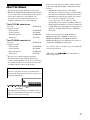
About area codes
The area code of the receiver you purchased is
shown on the lower portion of the rear panel (see
the illustration below).
Any differences in operation, according to the area
code, are clearly indicated in the text, for example,
“Models of area code AA only”.
FRONT R
SPEAKERS
FRONT L SUR R SUR L CENTER
SUBWOOFER
Area code

4
GB
Table of Contents
Description and location of parts...................5
Getting Started
1: Installing the speakers .............................12
2: Connecting the speakers ..........................15
3: Connecting the TV ..................................16
4: Connecting the audio/video
components.............................................17
5: Connecting the antennas..........................21
6: Preparing the receiver and the remote .....21
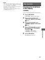
7: Calibrating the appropriate settings
automatically
(AUTO CALIBRATION) .......................23
8: Adjusting the speaker levels
(TEST TONE) ........................................27
Playback
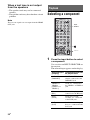
Selecting a component.................................28
Enjoying sound/images from the
components connected to the receiver....29
Amplifier Operations
Navigating through menus...........................32
Settings for the HDMI
(SET HDMI menu).................................35
Settings for the Auto Calibration
(A.CAL menu)........................................35
Settings for the speaker
(SP SETUP menu) ..................................36
Adjusting the level (LEVEL menu).............37
Adjusting the tone (TONE menu) ...............37
Custom settings (CUSTOM menu) .............38
Enjoying Surround Sound
Selecting the sound field..............................39
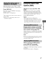
Tuner Operations
Listening to FM/AM radio.......................... 40
Presetting radio stations .............................. 41
Using the Radio Data System (RDS).......... 43
(Models of area code CEL, CEK only)
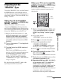
“BRAVIA” Sync Features
What is “BRAVIA” Sync? .......................... 44
Preparing for the “BRAVIA” Sync ............. 45
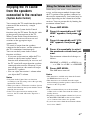
Playing back components with one-touch
operation (One-Touch Play)................... 46
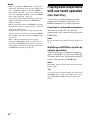
Enjoying the TV sound from the speakers
connected to the receiver
(System Audio Control)......................... 47
Turning off the receiver with the TV
(System Power Off) ............................... 48
Using the Power Saving function
(Power Save) .......................................... 48
Other Operations
Changing the brightness of the display
(DIMMER) ............................................ 49
Changing the display setting (DISPLAY)... 50
Using the Sleep Timer (SLEEP) ................. 50
Switching the audio input mode
(IN MODE)............................................ 51
Using the Remote
Changing the input button assignments ...... 51
Additional Information
Glossary ...................................................... 53
Precautions.................................................. 54
Troubleshooting .......................................... 56
Specifications.............................................. 60
Index ........................................................... 63

5
GB
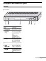
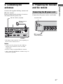
Description and location of parts
Front view
Receiver
ACTIVE STANDBY
INPUT SELECTOR
MASTER VOLUME
1 2 3 4 65
Name Function
A ?/1
(on/standby)
Press to turn the receiver
on or off (page 22, 29, 52).
B ACTIVE
STANDBY
lamp
Lights up in amber when
the Control for HDMI is
set to on and the receiver
is on standby mode.
Note
If the ACTIVE
STANDBY lamp is
flashing, see page 59.
C Display The current status of the
selected component or a
list of selectable items
appears here (page 6).
D Remote sensor Receives signals from
remote commander.
E INPUT
SELECTOR
Press to select the input
source to playback (page
28, 30, 31, 40, 41, 42).
F MASTER
VOLUME
Turn to adjust the volume
level of all speakers at the
same time (page 29, 30,
56).
continued

6
GB
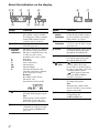
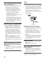
About the indicators on the display
2 4 51 3 6 7
89q;qaqs
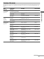
Name Function
A LFE Lights up when the disc being
played back contains an LFE
(Low Frequency Effect) channel
and the LFE channel signal is
actually being reproduced.
B SLEEP Lights up when the sleep timer is
activated (page 50).
C Playback
channel
indicators
L
R
C
SL
SR
S
The letters (L, C, R, etc.) indicate
the channels being played back.
The boxes around the letters vary
to show how the receiver
downmixes the source sound.
Front Left
Front Right
Center (monaural)
Surround Left
Surround Right
Surround (monaural or the
surround components obtained
by Pro Logic processing)
Example:
Recording format (Front/
Surround): 3/2.1
Sound Field: A.F.D. AUTO
D D Lights up when receiver is
decoding Dolby Digital signals.
Note
When playing a Dolby Digital
format disc, be sure that you
have made digital connections.
E HDMI Lights up when a playback
component is connected to this
receiver using an HDMI jack
(page 18).
L
CR
SL SR
SW
Name Function
F Preset
station
indicators
Lights up when using the receiver
to tune in radio stations you have
preset. For details on presetting
radio stations, see page 41.
G Tuner
indicators
Lights up when using the
receiver to tune in radio stations
(page 40), etc.
H COAX
Lights up when
the source signal
is a digital signal being input
through the COAX IN jack.
I OPT Lights up when the source signal
is a digital signal being input
through the OPT IN jack.
J PL/
PLII
“ PL” lights up when the
receiver applies Pro Logic
processing to 2 channel signals
in order to output the center and
surround channel signals.
“ PLII” lights up when the
Pro Logic II Movie/Music
decoder is activated.
K DTS Lights up when the receiver is
decoding DTS signals.
Note
When playing a DTS format
disc, be sure that you have made
digital connections.
L SW Lights up when the audio signal
is output from the
SUBWOOFER jack.

7
GB
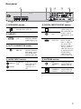
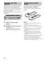
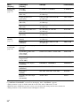
Rear panel
1 4 5 62 3
AM
ANTENNA
AUTO
CAL MIC
DMPORT
FRONT R
HDMI
SPEAKERS
FRONT L SUR R SUR L CENTER
SUBWOOFER
DC5V 700mA MAX
BD IN OUTSAT INDVD IN
AUDIO IN
VIDEO 1
VIDEO 2
L
R
L
R
AUDIO IN
SA-CD
/
CD
COAX IN
SAT
OPT IN OPT INAUDIO IN
TV
DIGITAL
TV
A SPEAKERS section
Connects to the supplied speakers
and subwoofer (page 15).
B DMPORT
DMPORT
jack
Connects to a
DIGITAL MEDIA
PORT adapter (page
17).
C AUTO CALIBRATION section
AUTO CAL
MIC jack
Connects to the
supplied optimizer
microphone for the
Auto Calibration
function (page 24).
D AUDIO INPUT section
AUDIO IN
jacks
Connects to a Super
Audio CD player,
CD player, etc.
(page 16, 17, 18,
20).
White (L)
Red (R)
E DIGITAL INPUT/OUTPUT section
OPT IN jacks Connects to a
satellite tuner, etc.
The COAX IN jack
provides a better
sound quality (page
20).
COAX IN
jack
HDMI IN/
OUT jacks
Connects to a DVD
player, satellite
tuner, or a Blu-ray
disc player. The
image is output to a
TV or a projector
while the sound can
be output from a TV
or/and speakers
connected to this
receiver (page 18).
F ANTENNA section
FM
ANTENNA
jack
Connects to the
supplied FM wire
antenna (page 21).
AM
ANTENNA
terminals
Connects to the
supplied AM loop
antenna (page 21).

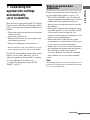
8
GB
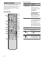
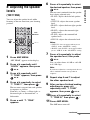
You can use the supplied RM-AAU058
Remote Commander to operate the receiver
and to control the Sony audio/video
components that the remote is assigned to
operate (page 51).
RM-AAU058
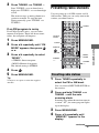
Basic operations
Remote commander
123
46
78
0
ENTER
9
SYSTEM STANDBY
DMPORT
VIDEO1 VIDEO2 BD DVD
RETURN/EXIT
TV CH
–
PRESET
–
TV CH
+
PRESET
+
TUNING
–
TV
TUNING
+
F1MENUTOP MENU F2
AMP MENU
CLEAR
DISPLAY
SOUND
FIELD
AUDIO
ANALOG
DIGITAL
THEATRE
SA-CD/CDTV TUNER
?/1
.
H
mM
X
x
<
<
>
5
TV
?/1
AV
?/1
TOOLS/
OPTIONS
MENU/HOME
SAT
BD/DVD
1
3
2
6
7
8
q;
qa
9
qf
qs
qd
4
5
qh
qk
qj
ql
w;
wa
qg
ws
Remote Button Function
B ?/1
(on/standby)
Press to turn the receiver on
or off.
To turn off all Sony
components, press ?/1 and
AV ?/1 (A) at the same
time (SYSTEM
STANDBY).
Saving the power in
standby mode
When “CONTROL FOR
HDMI” is set to “CTRL
ON” and “P.SAVE” is set to
“SAVE ON” (page 35).
C Input buttons Press one of the buttons to
select the component you
want to use. The buttons are
factory assigned to control
Sony components.
You can change the button
assignments following the
steps in “Changing the input
button assignments” on page
51.
G SOUND FIELD Press to select a sound field.
I AMP MENU Press to display the menu of
the receiver.
K
(Muting)
Press to turn off the sound.
Press again to restore the
sound.
L +*/– Press to adjust the volume.
Q
V/v/B/b
Press V, v, B or b to select
the settings. Then, press
to enter the selection.
,

9
GB
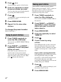
Tuner operations
DMPORT operations
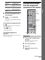
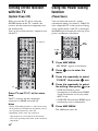
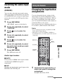
To control the component
1 Press one of the input buttons
(TV, BD, DVD or SAT) (C) to
select the component you want
to operate.
The component assigned to the selected
input button becomes operable.
2 Referring to the following table,
press the corresponding
button for the operation.
Common operations
To control the TV
Press and hold TV (yellow) button (O) while
pressing the buttons with an yellow dot or
yellow printing to control the TV.
Remote Button Function
H ENTER Press to enter the selection.
M MENU/HOME Press to display the menu.
N PRESET +/– Press to select preset
stations.
TUNING +/– Press to scan a station.
Q
V/v/B/b
Press to select a menu item
and enter the selection.
R DISPLAY Press to display information
during TUNER function.
S CLEAR Press to clear a mistake
when you input a wrong
character.
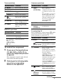
Remote Button Function
N ./> Press to skip the tracks.
m/M Press to fast reverse or to
fast forward.
H (playback)/
X (pause, press
again to resume
normal playback)/
x (stop)
Play mode buttons.
,
Remote Button Function
A TV ?/1
AV ?/1
(on/standby)
Press to turn on or off the
Sony audio/video
components that the remote
is assigned to operate (page
51).
Press ?/1 (B) and TV ?/1/
AV ?/1 (A) at the same
time to turn off the receiver
and other components that
the remote is assigned to
operate (SYSTEM
STANDBY).
H ENTER Press to enter the selection.
T Numeric
buttons
(number 5*)
Press to select channels and
tracks directly.
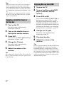
Remote Button Function
D AUDIO Press to select the desired
audio signal.
(Screen mode)
Press to change the screen
format manually to suit the
broadcast.
E THEATRE Press to set the optimal
picture settings
automatically for watching
movies, when you connect a
Sony TV which is
compatible with the
THEATRE button. Also, the
audio is automatically
switched to the audio output
of this receiver when you
connect the TV and the
receiver with HDMI
connection, and the Control
for HDMI function is set to
on.
F (Guide) Press to display the guide
when you are watching
analog and digital channels.
H
(Previous
channel)
Press to return to the
previous channel watched
(for more than five seconds).
continued

10
GB
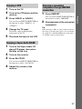
To control the DVD recorder/Blu-ray
Disc recorder
Remote Button Function
J TOOLS/
OPTIONS
Press to enable you to access
various viewing options and
change/make adjustments
according to the source and
screen format.
K
(Muting)
Press to turn off the sound.
L
+*/–
Press to adjust the volume.
M MENU/HOME Press to allow you to select
channels or input sources and
change the settings for your
TV.
N TV CH +/–
c/C
In TV mode: Press to select
the next (+) or previous (–)
channel.
In Text mode: Press to select
the next (c) or previous
(C) page.
P
RETURN/
EXIT
Press to return to the previous
screen of any displayed
menu.
Q
V/v/B/b
Press to select a menu item
and enter the selection.
R DISPLAY Press to display the TV’s
information on the TV
screen. (Displays the current
channel number, etc.)
/
(Info/Text
reveal)
In digital mode: Press to
display brief details of the
program currently being
watched.
In analogue mode: Press to
display information such as
current channel number and
screen format.
In Text mode: Press to reveal
hidden information (e.g.
answers to a quiz).
S
/ (Text) Press to display text.
T Numeric
buttons
(number 5*)
Press to select channels.
Press ENTER (H) to change
channels immediately.
U ANALOG Press to change to analog
mode.
DIGITAL Press to change to digital
mode.
,
Remote Button Function
V /
(Input select/
Text hold)
In TV mode: Press to select
input.
In Analogue Text mode:
Press to hold the current
page.
Remote Button Function
D F1 Press to select the HDD.
F2 Press to select the Blu-ray
Disc/DVD.
M MENU/HOME Press to display the menu.
N . Press to skip chapters.
Press to jump backward
while viewing live or
recorded programs.
Press to jump forward while
viewing recorded programs.
> Press to skip forward to the
next available chapter.
m/M Press to fast reverse or to
fast forward the disc when
pressed during playback.
H (playback)/
X (pause, press
again to resume
normal playback)/
x (stop)
Play mode buttons.
Q
V/v/B/b
Press to select a menu item
and enter the selection.
U BD/DVD
TOP MENU,
MENU
Press to display the top
menu or disc menu.
<
<
,

11
GB
To control the DVD player/
Blu-ray Disc player
To control the HDD/DVD COMBO
To control the SAT
* The number 5, 2 + and H buttons have tactile
dots. Use the tactile dots as references when
operating the receiver.
Notes
• Some functions explained in this section may not
work depending on the model.
• The above explanation is intended to serve as an
example only. Therefore, depending on the
component, the above operation may not be
possible or may operate differently than described.
Remote Button Function
M MENU/HOME Press to display the menu.
N ./> Press to skip chapters.
Press to jump backward.
Press to jump forward.
m/M Press to fast reverse or to
fast forward the disc when
pressed during playback.
H (playback)/
X (pause, press
again to resume
normal playback)/
x (stop)
Play mode buttons.
Q
V/v/B/b
Press to select a menu item
and enter the selection.
U BD/DVD
TOP MENU,
MENU
Press to display the top
menu or disc menu.
Remote Button Function
D F1 Press to select the HDD.
F2 Press to select the DVD.
M MENU/HOME Press to display the menu.
N ./> Press to specify the previous
or next chapter or track.
Press to change to replay
mode.
Press to advance.
m/M Press to fast reverse or to
fast forward the disc when
pressed during playback.
H (playback)/
X (pause, press
again to resume
normal playback)/
x (stop)
Play mode buttons.
Q
V/v/B/b
Press to move the highlight
(cursor) and select the item.
U BD/DVD
TOP MENU,
MENU
Press to display the top
menu or disc menu.
<
<
,
<
<
,
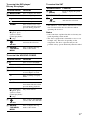
Remote Button Function
F
(Guide)
Press to display the guide
menu.
M MENU/HOME Press to display the menu.
Q
V/v/B/b
Press to select a menu item
and enter the selection.
,

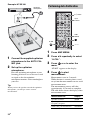
12
GB
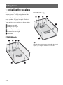
1: Installing the speakers
This receiver allows you to use a 5.1 channel
speaker system. To fully enjoy theater-like
multi channel surround sound, be sure to
connect all the speakers (two front speakers, a
center speaker, and two surround speakers)
and a subwoofer (5.1 channel).
You can place your speakers as shown below.
AFront speaker (left)
BFront speaker (right)
CCenter speaker
DSurround speaker (left)
ESurround speaker (right)
FSubwoofer
HT-SF100 only
HT-SS100 only
Tip
Since the subwoofer does not emit highly directional
signals, you can place it wherever you want.
Getting Started

13
GB
Getting Started
Before you install the speakers and subwoofer,
be sure to attach the supplied foot pads to
prevent vibration or movement as shown in the
illustration below.
Example of HT-SS100 front
speaker
Attach the supplied foot pads to the following
speakers.
For greater flexibility in positioning the
speakers, you are recommended to use the
speaker stand as below.
Installing the speakers on a flat
surface
Model Speakers
HT-SF100 Center speaker and subwoofer
HT-SS100 All the speakers and
subwoofer
Installing the speakers on the
speaker stand
Model Speaker stand
HT-SF100 Supplied. For details, refer to
the supplied speaker stand
installation guide.
HT-SS100 Optional WS-FV11 or
WS-FV10D speaker stand
(available only in certain
countries).
For details, refer to the
operating instructions supplied
with the speaker stand.

14
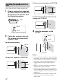
GB
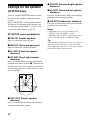
You can install your speakers on the wall.
1 Prepare screws (not supplied)
that are suitable for the hook on
the back of each speaker. See
the illustrations below.
2 Fasten the screws to the wall.
The screws should protrude
5 mm to 7 mm.
For the center speaker
For the front speakers of HT-SF100
For the surround speakers of HT-SF100
For the front speakers and surround
speakers of HT-SS100
3 Hang the speakers on the
screws.
Notes
• Use screws that are suitable for the wall material
and strength. As a plaster board wall is especially
fragile, attach the screws securely to a beam and
fasten them to the wall. Install the speakers on a
vertical and flat wall where reinforcement is
applied.
• Contact a screw shop or installer regarding the
wall material or screws to be used.
• Sony is not responsible for accident or damage
caused by improper installation, insufficient wall
strength or improper screw installation, natural
calamity, etc.
• For HT-SF100, if you install the speakers on the
wall, you do not need to attach the supplied
speaker stand.
Installing the speakers on the
wall
4 mm
more than 25 mm
4.6 mm
10 mm
Hook on the back of the speaker
5 mm to 7 mm
160 mm
5 mm to 7 mm
217 mm
5 mm to 7 mm
100 mm
5 mm to 7 mm
4.6 mm
10 mm
Rear of speaker

15
GB
Getting Started
2: Connecting the
speakers
Before connecting the cords, be sure to
disconnect the AC power cord.
AFront speaker (left)
BFront speaker (right)
CCenter speaker
DSurround speaker (left)
ESurround speaker (right)
FSubwoofer
Note on speaker cords
The connector of the speaker cords are the
same color as the speaker jack to be connected.
When connecting a speaker cord, be sure to
match the colored connector to the speaker
jack on the receiver:
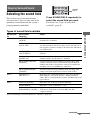
To connect the speakers
correctly
Check the speaker type by referring to the
speaker label* at the rear panel of the speakers.
* The center speaker and subwoofer do not have the
character on the speaker label. For details on the
speaker type, see page 3.
SPEAKERS
CENTER
SUBWOOFER
FRONT R FRONT L SUR R SUR L
E
B
A Speaker cord (supplied)
A
A
Connector
CF
D
A
A
Connector Speaker jack
Red FRONT R
White FRONT L
Grey SUR R
Blue SUR L
Green CENTER
Purple SUBWOOFER
Character on
speaker label
Speaker type
L Front left
R Front right
SL Surround left
SR Surround right

16
GB
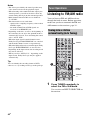
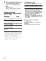
3: Connecting the TV
You can watch the selected input image when
you connect the HDMI OUT jack to a TV.
It is not necessary to connect all the cords.
Connect audio and video cords according to
the jacks of your components.
Before connecting the cords, be sure to
disconnect the AC power cord.
Notes
• Be sure to turn on the receiver when the video and
audio signals of a playback component are being
output to a TV via the receiver. Unless the power is
turned on, neither video nor audio signals will be
transmitted.
• When connecting optical digital cords, insert the
plugs straight in until they click into place.
• Do not bend or tie optical digital cords.
Tips
• To output the sound of the TV from the speakers
connected to the receiver, be sure to
– connect the audio output jacks of the TV to the
TV IN jacks of the receiver.
– turn off the TV’s volume or activate the TV’s
muting function.
• All the digital audio jacks are compatible with
32 kHz, 44.1 kHz, 48 kHz, and 96 kHz sampling
frequencies.
AM
ANTENNA
R
T
m
A MAX
AUDIO IN
VIDEO 1
VIDEO 2
R
L
R
AUDIO IN
SA-CD
/
CD
COAX IN
SAT
OPT INAUDIO IN
TV
DIGITAL
OPT IN
TV
HDMI
BD IN OUTSAT INDVD IN
L
TV
Audio signal
A
A Audio cord (not supplied)
B Optical digital cord (not supplied)
C HDMI cable (not supplied)
We recommend that you use a Sony HDMI
cable.
Audio/video
signal
BC

17
GB
Getting Started
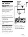
4: Connecting the audio/
video components
This section describes how to hook up your
components to this receiver. Before you begin,
see “Component to be connected” below for
the pages which describe how to connect the
audio/video components.
Before connecting the cords, be sure to
disconnect the AC power cord.
After hooking up all your components,
proceed to “5: Connecting the antennas” (page
21).
Component to be connected
The following illustration shows how to
connect audio components such as Super
Audio CD player or CD player and DIGITAL
MEDIA PORT adapter.
You can also view the images on the TV
screen by connecting the video output of the
DIGITAL MEDIA PORT adapter to the video
input of the TV. However, depending on the
DIGITAL MEDIA PORT adapter, video
output may not be possible.
* The type of connector varies depending on the
DIGITAL MEDIA PORT adapter.
For details, refer to the operating instructions
supplied with the DIGITAL MEDIA PORT
adapter.
How to hook up your
components
To connect See
TV page 16
Audio components
• Super Audio CD player/
CD player
• DIGITAL MEDIA PORT
adapter
page 17
Components with HDMI jack page 18
Video components
• DVD recorder, DVD player
• Satellite tuner, Set-top box
•VCR
page 20
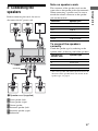
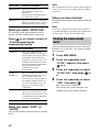
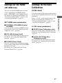
Connecting audio components
AM
ANTENNA
AUTO
CAL MIC
HDMI
BD IN OUTSAT INDVD IN
AUDIO IN
VIDEO 1
VIDEO 2
L
R
L
R
AUDIO IN
SA-CD
/
CD
COAX IN
SAT
OPT IN OPT INAUDIO IN
TV
DIGITAL
TV
DC5V 700mA MAX
DMPORT
Super Audio CD player,
CD player
Audio signal
A
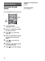
A Audio cord (not supplied)
B Video cord (not supplied)
B
TV
DIGITAL MEDIA
PORT adapter
continued

18
GB
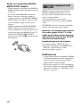
Notes on connecting DIGITAL
MEDIA PORT adapter
• Do not connect or disconnect the DIGITAL
MEDIA PORT adapter while the receiver is
turned on.
• Be sure to make DMPORT connections
firmly, insert the connector straight in.
• As the connector of the DIGITAL MEDIA
PORT adapter is fragile, be sure to handle
with care when placing or moving the
receiver.
• When connecting the DIGITAL MEDIA
PORT adapter, be sure the connector is
inserted with the arrow mark facing towards
the arrow mark on the DMPORT jack. To
detach the DIGITAL MEDIA PORT
adapter, press and hold A and then pull out
the connector.
HDMI is the abbreviated name for High-
Definition Multimedia Interface. It is an
interface which transmits video and audio
signals in digital format.
Sony recommends that you connect
components to the receiver using an HDMI
cable.
With HDMI, you can easily enjoy both high
quality sound and high quality images.
However, it is necessary to connect
the audio output of the TV to the
audio input of the receiver using an
optical cord to listen to the TV multi
channel surround sound
broadcasting from the receiver.
By connecting Sony “BRAVIA” Sync
compatible components using HDMI cables,
““BRAVIA” Sync Features” makes
operations simpler (page 44).
HDMI features
• A digital audio signals transmitted by HDMI
can be output from the speakers connected to
the receiver. This signal supports Dolby
Digital, DTS and Linear PCM.
• This receiver supports xvYCC transmission.
• This receiver supports the Control for HDMI
function. For details, see ““BRAVIA” Sync
Features” (page 44).
A
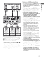
Connecting components with
HDMI jacks

19
GB
Getting Started
a)
Connect at least one of the audio cords (B or C).
* If you connect a DVD player, be sure to change the
factory setting of the DVD button on the remote so
that you can use the button to control your DVD
player. For details, see “Changing the input button
assignments” (page 51).
Notes on HDMI connections
• An audio signal input to the HDMI IN jack
is output from the SPEAKERS jacks and
HDMI OUT jack. It is not output from any
other audio jacks.
• Video signals input to the HDMI IN jack can
only be output from the HDMI OUT jack.
• The multi/stereo area audio signals of a
Super Audio CD are not output.
• Audio signals (sampling frequency, bit
length, etc.) transmitted from an HDMI jack
may be suppressed by the connected
component. Check the setup of the
connected component if the image is poor or
the sound does not come out of a component
connected via the HDMI cable.
• Sound may be interrupted when the
sampling frequency, the number of channels
or the audio format of the audio output
signals from the playback component is
switched.
• When the connected component is not
compatible with copyright protection
technology (HDCP), the image and/or the
sound from the HDMI OUT jack may be
distorted or may not be output.
In this case, check the specification of the
connected component.
• You can enjoy multi channel Linear PCM
only with an HDMI connection.
• Set the image resolution of the playback
component to 720p, 1080i or 1080p when
you output 96 kHz multi channel sound over
an HDMI connection.
• You may need to make certain settings on
the image resolution of the player before you
can enjoy multi channel Linear PCM. Refer
to the operating instructions of the player.
• Refer to the operating instructions of each
component connected for details.
• We do not recommend using an HDMI-DVI
conversion cable. When you connect an
HDMI-DVI conversion cable to a DVI-D
component, the sound and/or the image may
not be output.
AM
ANTENNA
RT
HDMI
mA MAX
AUDIO IN
VIDEO 1
VIDEO 2
R
L
R
AUDIO IN
SA-CD
/
CD
COAX IN
SAT
OPT INAUDIO IN
TV
DIGITAL
OPT IN
TV
OUT
L
SAT INDVD INBD IN
Satellite tuner/
Set-top box
A HDMI cable (not supplied)
We recommend that you use a Sony HDMI
cable.
B Optical digital cord (not supplied)
a)
C Audio cord (not supplied)
a)
DVD recorder,
DVD player*
Blu-ray disc
player
Audio/video
signals
Audio signals
TV, etc.
Audio/video
signals
AAA
ABC
Audio/video
signals
Audio/video
signals

20
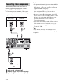
GB
The following illustration shows how to
connect video components such as DVD
player, DVD recorder, VCR, etc.
It is not necessary to connect all the cords.
Connect audio and video cords according to
the jacks of your components.
Notes
• To input multi channel digital audio from the DVD
player, set the digital audio output setting on the
DVD player. Refer to the operating instructions
supplied with the DVD player.
• When connecting optical digital cords, insert the
plugs straight in until they click into place.
• Do not bend or tie optical digital cords.
• Be sure to connect the video output of the DVD
player, DVD recorder and VCR to the TV, so that
the image is displayed on the TV. Refer to the
operating instructions of each connected
component for details.
• You cannot do recording on the DVD recorder or
VCR via this receiver. For details, refer to the
operating instructions supplied with the DVD
recorder or VCR.
Tip
All the digital audio jacks are compatible with
32 kHz, 44.1 kHz, 48 kHz, and 96 kHz sampling
frequencies.
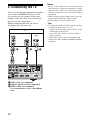
Connecting video components
AM
ANTENNA
DMPORT
HDMI
DC5V 700mA MAX
BD IN OUTSAT INDVD IN
L
R
L
R
AUDIO IN
SA-CD
/
CD
OPT INAUDIO IN
TV
TV
VIDEO 2
COAX IN
SAT
OPT IN
DIGITAL
AUTO
CAL MIC
AUDIO IN
VIDEO 1
DVD reco rder,
DVD player
Audio signal
A
A Audio cord (not supplied)
B Coaxial digital cord (not supplied)
C Optical digital cord (not supplied)
Audio signal
BC
Satellite tuner,
Set-top box
VCR
Audio signal
Page is loading ...
Page is loading ...
Page is loading ...
Page is loading ...
Page is loading ...
Page is loading ...
Page is loading ...
Page is loading ...
Page is loading ...
Page is loading ...
Page is loading ...
Page is loading ...
Page is loading ...
Page is loading ...
Page is loading ...
Page is loading ...
Page is loading ...
Page is loading ...
Page is loading ...
Page is loading ...
Page is loading ...
Page is loading ...
Page is loading ...
Page is loading ...
Page is loading ...
Page is loading ...
Page is loading ...
Page is loading ...
Page is loading ...
Page is loading ...
Page is loading ...
Page is loading ...
Page is loading ...
Page is loading ...
Page is loading ...
Page is loading ...
Page is loading ...
Page is loading ...
Page is loading ...
Page is loading ...
Page is loading ...
Page is loading ...
Page is loading ...
Page is loading ...
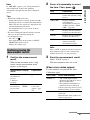
-
 1
1
-
 2
2
-
 3
3
-
 4
4
-
 5
5
-
 6
6
-
 7
7
-
 8
8
-
 9
9
-
 10
10
-
 11
11
-
 12
12
-
 13
13
-
 14
14
-
 15
15
-
 16
16
-
 17
17
-
 18
18
-
 19
19
-
 20
20
-
 21
21
-
 22
22
-
 23
23
-
 24
24
-
 25
25
-
 26
26
-
 27
27
-
 28
28
-
 29
29
-
 30
30
-
 31
31
-
 32
32
-
 33
33
-
 34
34
-
 35
35
-
 36
36
-
 37
37
-
 38
38
-
 39
39
-
 40
40
-
 41
41
-
 42
42
-
 43
43
-
 44
44
-
 45
45
-
 46
46
-
 47
47
-
 48
48
-
 49
49
-
 50
50
-
 51
51
-
 52
52
-
 53
53
-
 54
54
-
 55
55
-
 56
56
-
 57
57
-
 58
58
-
 59
59
-
 60
60
-
 61
61
-
 62
62
-
 63
63
-
 64
64


Ask a question and I''ll find the answer in the document
Finding information in a document is now easier with AI
Related papers
-
Sony Stereo Amplifier TA-FA1200ES User manual
-
-
Sony STR-DH700 Operating instructions
-
Sony STR-DH500 Operating instructions
-
Sony RHT-G800 Operating instructions
-
Sony HT-CT100 User manual
-
Sony STRDG720 User manual
-
Sony STR-DG710 User manual
-
-
