Page is loading ...

Bedienungsanleitung
VC-740E AC Zangen-Multimeter
Best.-Nr. Seite 2 - 32
Operating Instructions
VC-740E AC clamp multimeter
Item No. Page 33 - 63
Mode d’emploi
Multimètre à pince CA VC-740E
N° de commande Page 64 - 94
Gebruiksaanwijzing
VC-740E AC tangmultimeter
Bestelnr. Pagina 95 - 125
1500204
1500204
1500204
1500204

33
Table of contents
Page
1. Introduction ......................................................................................................................................................... 34
2. Explanation of symbols ....................................................................................................................................... 35
3. Intended use ....................................................................................................................................................... 36
4. Delivery content .................................................................................................................................................. 37
5. Safety instructions .............................................................................................................................................. 38
6. Product overview ................................................................................................................................................ 40
7. Product description ............................................................................................................................................. 41
8. Display and symbols ........................................................................................................................................... 42
9. Taking measurements ......................................................................................................................................... 44
a) Switching on the multimeter ......................................................................................................................... 44
b) Alternating voltages (V/AC) .......................................................................................................................... 44
c) Direct voltages (V/DC) .................................................................................................................................. 45
d) LoZ alternating voltages ............................................................................................................................... 45
e) Measuring current ......................................................................................................................................... 46
f) Measuring the signal current (µA) ................................................................................................................ 47
g) Measuring resistance .................................................................................................................................. 48
h) Diode test ..................................................................................................................................................... 49
i) Continuity test .............................................................................................................................................. 49
j) Measuring capacitance ................................................................................................................................. 50
k) Measuring frequency (electronic) ................................................................................................................. 50
l) Measuring the temperature .......................................................................................................................... 51
10. Additional functions ............................................................................................................................................. 53
a) SELECT function .......................................................................................................................................... 53
b) RANGE - Manually selecting the measuring range ...................................................................................... 53
c) MAX/MIN function ......................................................................................................................................... 53
d) REL function ................................................................................................................................................. 54
e) Hz function (measuring the electrical frequency) ......................................................................................... 54
f) HOLD function .............................................................................................................................................. 54
g) Display backlight ........................................................................................................................................... 54
h) Automatic switch-off feature ......................................................................................................................... 55

34
1. Introduction
Dear customer,
Thank you for purchasing this product.
This product complies with statutory national and European regulations.
For safety reasons, always follow the instructions in this manual.
These operating instructions are part of this product. They contain important information on setting up and
using the product. Please consider this if you pass on the product to a third party, and keep the operating
instructions for future reference.
If there are any technical questions, please contact:
International: www.conrad.com/contact
United Kingdom: www.conrad-electronic.co.uk/contact
Page
11. Cleaning and maintenance ................................................................................................................................. 55
a) General information ...................................................................................................................................... 55
b) Cleaning ....................................................................................................................................................... 55
c) Removing the battery compartment cover .................................................................................................... 56
d) Inserting/changing the batteries ................................................................................................................... 56
12. Disposal .............................................................................................................................................................. 57
13. Troubleshooting .................................................................................................................................................. 58
14. Technical data ..................................................................................................................................................... 59

35
2. Explanation of symbols
The symbol with the lightning in the triangle indicates that there is a risk to your health, e.g. due to an
electric shock.
The lightning symbol in the square permits current measurements on uninsulated, hazardous active con-
ductors and warns of the possible hazards. Personal protective equipment must be used.
This symbol is used to highlight important information in these operating instructions. Always read this
information carefully.
This symbol indicates special information and advice on how to use the product.
This product has been CE tested and complies with the necessary European guidelines.
Protection class 2 (double or reinforced insulation, protective insulation)
IP54 Dust- and splash-proof.
CAT I Measurement Category I: For measuring circuits of electrical and electronic equipment that is not directly
supplied with a mains voltage (e.g. battery-operated devices, safety extra-low voltage systems, and signal/
control voltages). In the future, this category will be renamed CAT 0 or 0.
CAT II Measurement Category II: For measuring electrical and electronic devices that are directly supplied with a
mains voltage via a mains plug. This category also includes all lower categories (e.g. CAT I for measuring
signal and control voltages).
CAT III Measurement Category III: For measuring circuits of installations in buildings (e.g. mains sockets or sub-
distributions). This category also includes all lower categories (e.g. CAT II for measuring electrical devices).
Measuring in CAT III is only permitted with test prods that are covered with caps or that have a maximum
exposed contact length of 4 mm.
CAT IV Measurement Category IV: For measuring at the origin of a low-voltage installation (e.g. mains distribution,
electricity provider’s transfer points to homes) and outdoors (e.g. when conducting tasks on underground
cables or overhead lines). This category also includes all smaller categories. Measuring in CAT IV is only
permitted with test prods that are covered with caps or that have a maximum exposed contact length of
4 mm.
Earth potential

36
3. Intended use
• Measures and displays electrical parameters in measurement category CAT IV (up to 600V). Complies with the
EN 61010-1 standard and all lower categories.
• MeasuresDCvoltagesupto600V(10MΩimpedance)
• MeasuresACvoltagesupto600V(10MΩimpedance)
• MeasuresACvoltagesupto600Vwithalowimpedance(300kΩ)
• Measures direct and alternating currents up to 2000 µA (signal currents)
• Contactless measurement of direct and alternating currents up to 600 A
• Measures frequencies from 10 Hz to 40 MHz (electronic, max. 30 Vrms) or from 40 to 400 Hz (electrical,
30–600 Vrms as sub-mode)
• Measures capacitance up to 60 mF
• Measuresresistanceupto60MΩ
• Measures temperatures from -40 to +1000 °C.
• Continuitytest(<10Ωacoustic)
• Diode test
• 3-phase rotation indicator for the voltage range 80–600 V/AC
Use the control knob to select the measuring mode. The measuring range is selected automatically in all measuring
modes (except motor, diode test, continuity test and microampere modes).
Effective (True RMS) measurements are displayed when measuring AC voltages/currents with a frequency of up to
400 Hz.
For negative readings, the polarity is indicated with the (-) sign.
The µA current measurement input is protected against overload by a resettable fuse (PTR). The voltage in the
measuring circuit may not exceed 600 V.
ThemultimeterispoweredbythreeAAAbatteries.Onlyusebatteriesofthespeciedtype.Donotuse1.2Vrechar-
geable batteries.
The device switches off automatically after 15 minutes if no buttons are pressed. This prevents the battery from drai-
ning. This automatic switch-off function can be disabled.
Do not use the multimeter when the battery compartment is open.
The multimeter has an IP54 protection rating, meaning that it is dust and splash-proof. However, do not use the
multimeter when it is wet or damp.
Do not take measurements in potentially explosive areas, damp rooms or adverse environmental conditions. Adverse
conditionsinclude:Moistureorhighhumidity,dustandammablegases,vapoursorsolvents,thunderstorms,and
strongelectromagneticelds.
Forsafetyreasons,onlyusetestleadsandaccessoriesthatconformtothemultimeterspecications.

37
The device must only used by people who have the necessary physical and mental skills to ensure that measure-
ments are taken safely. The user must also be familiar with regulations on taking measurements and the possible
hazards. The use of personal protective equipment is recommended.
Any use other than that described above may damage the product and cause additional hazards such as a short
circuit,re,orelectricshock.Theproductmustnotbemodiedorreassembled!
Read the operating instructions carefully and keep them in a safe place for future reference.
Always observe the safety information in these instructions.
4. Delivery content
• Clamp multimeter
• 3 x AAA batteries
• 2 x CAT IV safety test leads
• Temperature probe (-40 to +250 °C type K)
• Safety instructions
• Operating instructions (on CD)
Up-to-date operating instructions
Download the latest operating instructions via the link www.conrad.com/downloads or scan the QR code. Follow the
instructions on the website.

38
5. Safety instructions
Read the operating instructions and safety information carefully. If you do not follow the safety
instructions and information on proper handling in this manual, we assume no liability for any
resulting personal injury or damage to property. Such cases will invalidate the warranty/guarantee.
• This device was shipped in a safe condition.
• To ensure safe operation and avoid damaging the product, always observe the safety information and
warnings in these instructions.
• For safety and approval reasons, do not attempt to convert and/or modify the device.
• Consult a technician if you are not sure how to use or connect the device.
• Measuring instruments and their accessories are not toys and should be kept out of the reach of children.
• Always comply with accident prevention regulations for electrical equipment when using the product in
industrial facilities.
• In schools, educational facilities, hobby and DIY workshops, measuring devices must be operated under
theresponsiblesupervisionofqualiedpersonnel.
• Before each measurement, always make sure that the meter is set to the correct measurement mode.
• When using measuring probes without protective caps, measurements
between the multimeter and the earth potential must not exceed the CAT II
measurement category.
• When taking CAT III and CAT IV measurements, the cover caps must be
placed on the probe tips (max. length of exposed contacts = 4 mm) to avoid
accidental short circuits. These are supplied with the device.
• Always remove the test probes from the measured object before changing the measurement mode.
• The voltage between the multimeter connection points and earth must never exceed 600 V DC/AC in
CAT IV.
• Exercise particular caution when dealing with voltages exceeding 33 V/AC or 70 V/DC. Touching electri-
cal conductors at these voltages may result in a fatal electric shock.
• To prevent an electric shock, do not touch the measuring points when taking measurements, either
directly or indirectly. When taking measurements, do not grip beyond the grip markings on the multimeter
and test probes.
• Check the measuring device and test leads for signs of damage before each measurement. Never take
measurements if the protective insulation is damaged (torn, missing, etc.). The measuring cables come
with a wear indicator. If a cable is damaged, a second layer of insulation will become visible (the second
layer of insulation is a different colour). If this happens, discontinue use and replace the measurement
accessory.
• Do not use the multimeter before, during or after a storm (risk of electric shock / power surge). Ensure
thatyourhands,shoes,clothes,theoor,circuitandcircuitcomponentsaredry

39
• Avoid using the device in the immediate vicinity of:
- Strongmagneticorelectromagneticelds
- Transmitting antennas or HF generators.
- These may distort the measurements.
• If you have reason to assume that safe operation is no longer possible, disconnect the device immediate-
ly and prevent it from being used unintentionally. Safe operation can no longer be guaranteed if:
- There are signs of damage
- The device does not function properly
- The device was stored under unfavourable conditions for a long period of time
- The device was subjected to rough handling during transport
• Do not switch the device on immediately after it has been brought from a cold room into a warm one. The
condensation generated may destroy the product. Leave the device switched off and allow it to reach
room temperature.
• Do not leave packaging material unattended, as it may become dangerous playing material for children.
• Observe the safety information in the individual chapters.

40
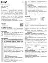
6. Product overview
1 Current clamp
2 Grip area
3 Sensor for automatic display backlight
4 Opening lever
5 SELECT button for switching modes
6 Display
7 Soft rubber seal
8 RANGE button for changing the measuring range
9 REL button for measuring the reference value
10 COM test socket
(Reference potential, “negative potential”)
11 test socket
(“Positive potential” for direct voltage)
12 Hz button for displaying the frequency
13 MAX/MIN button for displaying the maximum/mini-
mum readings
14 Disables automatic backlight
15 Screw for battery compartment
16 Control knob for selecting the measuring mode
17 Hold button to retain measurements

41
7. Product description
The multimeter displays measurements on a digital display. The multimeter has 6000 counts (count = smallest
display value). The true RMS value is used when measuring AC voltages and currents.
To prolong the battery life, the multimeter switches off automatically after 15 minutes of inactivity. The automatic
switch-off function can be manually disabled.
The meter can be used for DIY, professional, and industrial purposes up to CAT IV. The rubber seal gives the multi-
meter a robust design and enables it to withstand falls from up to 2 m. The multimeter is also dust and splash-proof
(IP54). Before replacing the batteries or fuse, check that the battery compartment seal is clean and intact. Remove
dirt and dust with a thin cotton swab. The seal must not be damaged. Do not apply grease or other sealants, as this
may affect the safety of the device.
Protective caps may be attached to the test lead plugs. Remove these before inserting the test leads into the
multimeter.
Control knob (16)
Use the control knob to select a measuring mode/range. Automatic
range selection (“AUTO”) is enabled in most measuring modes. This
means that the appropriate measurement range will be selected
automatically.
To select the modes marked in red, press the “SELECT” button (e.g.
to switch from resistance to continuity test or AC to DC). To select
“MOTOR” mode, move the control knob to the “V” position, then
press and hold the “SELECT” button for 2 seconds.
To turn the multimeter off, move the control knob to the “OFF” positi-
on. Always turn the multimeter off when it is not in use.

42
8. Display and symbols
The display contains the following symbols.
1 True root mean square
2 Diode test symbol
3 Acoustic continuity tester
4 Volt (unit of electrical voltage)
5 Micro symbol
6 Ampere (unit of electrical current)
7 Nano symbol
8 Milli symbol
9 Micro symbol
10 Farad (unit of electrical capacity)
11 Mega symbol
12 Kilo symbol
13 Ohm (unit of electrical resistance)
14 Hertz (unit of frequency)
15 Degrees Celsius (unit of temperature)
16 Degrees Fahrenheit (unit of temperature)
17 Measured value
18 3-phase rotation direction indicator (“clockwise”)
19 Backlight enabled
20 Lockiconforphasedetection(ashing=detectionmode,constant=phasedetected)
21 Delta symbol for relative value measurements (=reference value measurement)
22 Minimum value
23 Maximal value
24 3-phase rotation direction indicator (“anticlockwise”)
25 Automatic measurement range is enabled
26 Automatic shut-off is enabled
27 Battery level indicator
28 Hold function is enabled
29 Warning symbol for dangerous voltage (with warning sound when the measuring range is exceeded)
30 Direct current ( )
31 Polarityindicatorforcurrentowdirection(negativepole)
32 Alternating current ( )
33 Low impedance

43
REL Relative value button (= reference value measurement)
SELECT Switch to sub-functions
RANGE Manually select measuring range
MAX MIN Maximum/minimum memory
HOLD Freezes the current measurement
OL Overload = the measuring range was exceeded
OFF Move to this position to turn the multimeter off
Low battery warning (replace the battery)
Diode test symbol
Acoustic continuity tester
Capacity measuring range
°C °F Temperature unit (degrees Celsius/Fahrenheit)
Alternating current
Direct current
COM Connection for reference potential
V Voltage mode (Volt = unit of electrical voltage)
A Current mode (Ampere = unit of electric current)
µA Current mode (Micro-Ampere)
Hz Frequency mode (Hertz = unit of frequency)
Ω Resistancemode(Ohm=unitofelectricalresistance)
Motor 3-phase rotation direction indicator
LoZ Low-impedance(300kΩ)
Disables automatic backlight
Indicates the direction of the current when taking current clamp measurements (not relevant)
Indicates the direction of the current when taking current clamp measurements (not relevant)

44
9. Taking measurements
Never exceed the maximum permitted input values. Never touch circuits or circuit components if
they may carry voltages greater than 33 V/ACrms or 70 V/DC. This may cause a fatal electric shock!
Before measuring, check the connected test leads for damage, such as cuts, tears and kinks. Never
use damaged test leads, as this may cause a fatal electric shock!
When taking measurements, do not touch any exposed areas beyond the grip markings on the test
probes and the multimeter.
Only connect the test leads that you require. For safety reasons, remove all unnecessary test leads
from the device before taking a measurement.
Measurementsin circuits ratedat >33 V/ACand >70 V/DCmust only bemade by qualiedand
trained personnel who are familiar with the relevant regulations and the associated hazards.
“OL” (overload) indicates that the measuring range has been exceeded.
a) Switching on/off the multimeter
Turn the control knob (16) to the desired measuring mode. To turn the multimeter off, move the control knob (16) to
the “OFF” position. Always turn the multimeter off when it is not in use.
When you turn the multimeter on, a short function test will be conducted and all symbols will appear on the display.
The multimeter will beep when the test is complete.
Insert the batteries before using the multimeter. For more information on inserting/replacing the batteries,
see “Cleaning and Maintenance”.
b) Alternating voltages (V/AC)
Measuring AC voltages (V ):
- Turn the multimeter on and select “V ” mode. “AC” and “V” will appear on the
display.
- Insert the red test lead into the socket (11) and the black test lead into the
COM socket (10).
- Connect the two measuring probes in parallel to the object that you want to measu-
re (e.g. generator or circuit).
- The measured voltage will appear on the display.
- After measuring, remove the measuring leads from the measured object and turn
the multimeter off.
The“V/AC”voltagerangehasaninput resistanceof≥10 MΩ,meaning
there is almost no impact on circuit performance.

45
c) Direct voltages (V/DC)
Measuring DC voltages (V ):
- Turn the multimeter on and select “V ” mode.
- Press “SELECT” to switch to DC mode. “DC” and “V” will appear on the display.
- Insert the red test lead into the socket (11) and the black test lead into
the COM socket (10).
- Connect the two measuring probes in parallel to the object that you want to
measure (e.g. battery or circuit). The red test prod corresponds to the positive
terminal; the black test prod corresponds to the negative terminal.
- The polarity of the measured value is indicated on the display.
- After measuring, remove the measuring leads from the measured object and
turn the multimeter off.
A minus symbol indicates that the measured DC voltage is negative (or that the measuring leads are con-
nected in the wrong polarity).
The“V/DC”voltagerangehasaninputresistanceof≥10MΩ,meaningthereisalmostnoimpactoncircuit
performance.
d) LoZ alternating voltages
LoZmodeallowsyoutomeasurealternatingvoltageswithalowimpedance(approx.300kΩ).Inthismode,the
multimeter lowers the internal resistance to prevent ‘phantom’ voltage readings. As a result, the circuit is more heavi-
ly loaded than in the standard measuring mode.
Measuring LoZ alternating voltages (V ):
- Turn the multimeter on and select “LoZ V ” mode. “LoZ AC” and “V” will ap-
pear on the display.
- Insert the red test lead into the socket (11) and the black test lead into
the COM socket (10).
- Connect the two measuring probes in parallel to the object that you want to
measure (e.g. generator or circuit).
- The measured voltage will appear on the display.
- After measuring, remove the measuring leads from the measured object and
turn the multimeter off.
The “LoZ V/AC” voltage rangehasaninput resistance of <300 kΩ,
which may slightly affect circuit performance.

46
e) Measuring current
Never exceed the maximum permitted input values. Never touch circuits or circuit components if
they may carry voltages greater than 33 V/ACrms or 70 V/DC. This may cause a fatal electric shock!
Do not measure current on a circuit with a voltage of more than 600 V in CAT IV.
Pay attention to the necessary safety information, regulations and protective measures for your
own safety.
Thecurrentismeasuredviathecurrentclamp(1).Thesensorsinthecurrentclampdetectthemagneticeldcreated
by current-carrying conductors. You can take measurements on insulated and uninsulated conductors. Always ensure
that the conductor passes through the centre of the current clamp (pay attention to the arrow marks) and that the
clamp is closed.
Do not use the current clamp to surround more than one conductor. If the
supply and return conductors (e.g. L and N) are measured, the currents will
cancel each other out and no measurement will be displayed. If several sup-
ply conductors (e.g. L1 and L2) are measured, the currents will be added
together.
At low currents, the conductor can be wound around one side of the current
clamp to increase the total measured current. To obtain the correct current
value, divide the measured current by the number of coils.
Measuring alternating currents (A ):
- Turn on the multimeter using the control knob (16) and select “A
” mode. “A” and the AC symbol AC will appear on the display.
- The display is automatically set to zero when the current clamp is
closed.Ifthereisastrongmagneticeldthataffectsthereading,
use the relative value function (“REL”).
- Press the opening lever (4) to open the current clamp.
- Surround the conductor that you want to measure and close the
current clamp. Position the conductor in the middle between the
two markings on the clamp.
- The measured current is indicated on the display.
After measuring, remove the current clamp from the measured ob-
ject and turn the multimeter off (turn the control knob to the “OFF”
position).

47
f) Measuring the signal current (µA)
You can use the multimeter to measured direct and alternating signal currents up to 2000 µA. The test leads are
connected via the two measurement sockets. The µA current input is protected against overload with a resettable
fuse. The fuse does not need to be replaced in the event of an overload. The fuse components limit the current to
prevent a defect.
Measuring direct currents (µA ):
- Turn the multimeter on and select “µA ” mode.
- Insert the red test lead into the socket (11) and the black test lead
into the “COM” socket (10).
- Connect the two measuring probes in parallel to the object that you want
to measure (e.g. battery or circuit). The electrical circuit must be discon-
nected before you connect the probes.
- Reconnect the circuit.
- The measured value and polarity are indicated on the display.
- After measuring, disconnect the circuit and remove the test leads from the
measured object. Switch the multimeter off.
Aminussymbolindicatesthatthecurrentisowingintheoppo-
site direction (or that the measuring leads are connected in the
wrong polarity).
Measuring alternating currents (A ):
- Turn the multimeter on and select “µA” mode.
- Press “SELECT” to switch to AC mode. “AC” will appear on the display.
- Connect the multimeter as described in “Measuring direct currents”.
- After measuring, disconnect the circuit and remove the test leads from the
measured object. Switch the multimeter off.

48
g) Measuring resistance
Make sure that all objects to be measured (including circuit components, circuits and component
parts) are disconnected and discharged.
Proceed as follows:
- Turnthemultimeteronandselect“Ω”mode.
- Insert the red test lead into the socket (11) and the black test lead into
the COM socket (10).
- Check the test leads by connecting the two test probes together. A resistance
value of approx 0–0.5 Ω should be shown (inherent resistance of the test
leads). The lead resistance in high-impedance measurements is negligible.
- For low-impedance measurements, press the “REL” button (9) to discount
the inherent impedance of the test leads in the resistance measurement. The
displaywillberesetto0Ωandautomaticrangeselection(“AUTO”)willbe
disabled.
- Connect the two test probes to the object that you want to measure. The mea-
surement will be indicated on the display (provided that the object you are
measuring is not highly resistive or disconnected). Wait until the display stabili-
ses.Thismaytakeafewsecondsforresistancesgreaterthan1MΩ.
- “OL” (overload) indicates that the measuring range has been exceeded or that
the circuit was disconnected.
- After measuring, remove the test leads from the measured object and turn the
multimeter off.
When taking a resistance measurement, make sure that the measuring points you touch with the probe
tips are free from dirt, oil, solder lacquer and other similar substances. These substances may distort the
measurement.
The “REL” button only works when a measured value is displayed. It cannot be used when “OL” is dis-
played.

49
h) Diode test
Make sure that all objects to be measured (including circuit
components, circuits and component parts) are disconnected
and discharged.
- Turn the multimeter on and select mode.
- Press “SELECT” twice to switch the measurement mode. The diode symbol
and “V” will appear on the display. Press the button again to switch to the
next measuring mode.
- Insert the red test lead into the socket (11) and the black test lead
into the COM socket (10).
- Check the test leads by connecting the two test probes together. A value of
approx. 0.000 V should be shown.
- Connect the two test probes to the object that you want to measure
(diodes).
- The continuity voltage (“UF”) will be shown in Volts (V). “OL” indicates that
the diode is reverse-biased or defective. Try taking the measurement again
in the opposite polarity.
- After measuring, remove the test leads from the measured object and turn
the multimeter off.
i) Continuity test
Make sure that all objects to be measured (including circuit
components, circuits and component parts) are disconnected
and discharged.
- Turn the multimeter on and select mode.
- Press the “SELECT” button to switch measurement modes. The continuity
testsymbolandtheΩsymbolwillappearonthedisplay.Pressthebutton
again to switch to the next measuring mode.
- Insert the red test lead into the socket (11) and the black test lead
into the COM socket (10).
- Ifthemeasuredresistanceisequaltoorlessthan10Ω,themultimeterwill
beep to indicate continuity. The continuity test measures resistances of up
to 600 Ohm.
- “OL” (overload) indicates that the measuring range has been exceeded or
that the circuit was disconnected.
- After measuring, remove the test leads from the measured object and turn
the multimeter off.

50
j) Measuring capacitance
Make sure that all objects to be measured (including circuit
components, circuits and component parts) are disconnected
and discharged.
Always pay attention to the polarity when using electrolytic
capacitors.
- Turn the multimeter on and select mode.
- Insert the red test lead into the
socket (11) and the black test lead
into the COM socket (10).
Due to the sensitive measuring input, the display may show a rea-
ding even with “open” measuring leads. Press the “REL” button to
reset the display to “0”. Automatic range selection will be disabled.
This is recommended for small capacitances in the nF range.
- Connect the two test probes (red = positive / black = negative) to the object
that you want to measure (capacitor). The capacitance will be shown on the
display after a few seconds. Wait until the display stabilises. This may take
a few seconds for capacitances greater than 40 µF.
- “OL” (overload) indicates that the measuring range has been exceeded.
- After measuring, remove the measuring leads from the measured object
and turn the multimeter off.
k) Measuring frequency (electronic)
The multimeter can be used to measure signal voltage frequencies from 10
to 40 MHz. The maximum input is 30 Vrms. This mode is not suitable for ta-
kingmeasurementsonmainsvoltages.Observetheinputspecicationsinthe
technical data.
For mains voltages, use the “Hz” function in voltage or current mode.
Proceed as follows:
- Turn the multimeter on and select “Hz” mode. “Hz” will appear on the display.
- Insert the red test lead into the socket (11) and the black test lead
into the COM socket (10).
- Connect the two measuring probes in parallel to the object that you want to
measure (e.g. signal generator or circuit).
- The frequency will be displayed together with the corresponding unit..
- After measuring, remove the test leads from the measured object and turn
the multimeter off.

51
l) Measuring the temperature
When taking a temperature measurement, only allow the temperature probe to come into contact
with the surface of the measured object. The multimeter must not be exposed to temperatures
below or in excess of the operating temperature, as this may lead to incorrect measurements.
The temperature probe must only be used on voltage-free surfaces.
The multimeter features a wire sensor that can measure temperatures from -40
to + 250 °C. To use the full temperature range (-40 bis +1000 °C), purchase a
Type-K thermal sensor. An adapter plug is required to connect Type-K sensors
with a miniature connector.
All K-type thermal sensors can be used for taking temperature measurements.
The temperature can be displayed in °C or °F.
Proceed as follows:
- Turn the multimeter on and select “°C °F” mode. The temperature unit (°C) will
appear on the display.
- Insert the Type-K wire sensor into the and COM sockets in the correct
polarity.
- When using a thermal sensor with miniature connectors, connect the sensor
to a compatible adapter. The two contacts on the thermal sensor plug have a
different width to ensure that they are connected correctly.
- The display shows the temperature in °C.
- Press “SELECT” to switch the unit from °C to °F.
- “OL” indicates that the measurement range was exceeded or the sensor was
disconnected.
- After measuring, remove the sensor and turn off the multimeter.
/