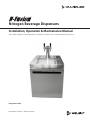
MULTIPLEX N2-Fusion ND21RS00 Installation, Operation & Maintenance Manual
- Category
- Coffee makers
- Type
- Installation, Operation & Maintenance Manual

Part Number: 9290312 October/22/2018
Nitrogen Beverage Dispensers
Installation, Operation & Maintenance Manual
This manual is updated as new information and models are released. Visit our website for the latest manual.
Original Document

Safety Notices
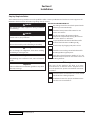
DEFINITIONS
DANGER
Indicates a hazardous situation that, if not avoided, will
result in death or serious injury. This applies to the most
extreme situations.
n
Warning
Indicates a hazardous situation that, if not avoided,
could result in death or serious injury.
,
Caution
Indicates a hazardous situation that, if not avoided,
could result in minor or moderate injury.
Notice
Indicates information considered important, but not
hazard-related (e.g. messages relating to property
damage).
NOTE: Indicates useful, extra information about the procedure you are performing.

Table of Contents
Part Number: 9290312 October/22/2018 3
Safety Notices ..................................................................................................................... 2
Definitions.................................................................................................................................................2
Section 1
General Information
Read This Manual ...............................................................................................................5
About N
2
Fusion™ ................................................................................................................ 5
Unit Inspection ................................................................................................................... 5
Model Numbers .................................................................................................................. 5
Serial Number Location .....................................................................................................5
Warranty Information ........................................................................................................ 5
Specifications .....................................................................................................................6
Dimensions ...............................................................................................................................................6
Capacity & Weight ..................................................................................................................................6
Product Delivery Location ...................................................................................................................7
Refrigerant Charge .................................................................................................................................7
Electrical ....................................................................................................................................................8
Section 2
Installation
Step-by-Step Installation .................................................................................................11
Pre-installation Checklist .................................................................................................................. 11
Remote Tower Installation ............................................................................................................... 12
Nitrogen Regulator & Tank Assembly .......................................................................................... 13
Nitrogen Installation/Replacement .............................................................................................. 13
Nitrogen Connections & Pressures ............................................................................................... 14
N
2
Quick Disconnect & Drain ........................................................................................................... 14
Keg & Pump Regulators ....................................................................................................................15
Keg Connections ................................................................................................................................. 15
Plumbing Diagram ..............................................................................................................................17
Door Hinge Reversal........................................................................................................................... 18
Section 3
Operation
Machine Operation ..........................................................................................................19
Controls/Programming/Settings ................................................................................................... 19
Prime / Clean Button .......................................................................................................................... 19
Clearing Error Code ............................................................................................................................20
Priming the System ............................................................................................................................ 20
Taps & Nozzles ...................................................................................................................................... 20
Keg Change ........................................................................................................................................... 21
Nitrogenator ......................................................................................................................................... 22

4 Part Number: 9290312 October/22/2018
Table of Contents (continued)
Section 4
Maintenance
Cleaning & Sanitizing .......................................................................................................23
General Cleaning ................................................................................................................................. 24
Cleaning Supplies ............................................................................................................................... 24
Manual Keg Cleaning ......................................................................................................................... 25
Level 1 - Daily Cleaning ..................................................................................................................... 26
Level 2 - Weekly Cleaning (Single Step Method) ..................................................................... 29
Level 2 - Weekly Cleaning (Three Step Method) ...................................................................... 31
Level 3 - Monthly Cleaning .............................................................................................................. 34
Other Operations .............................................................................................................35
Doors & Hinges .................................................................................................................................... 35
Section 5
Troubleshooting
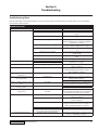
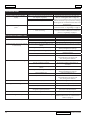
Troubleshooting Charts ...................................................................................................37
Dispensing Issues ................................................................................................................................ 37
Refrigerator Cabinet Issues ..............................................................................................................38
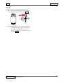
Pouring ....................................................................................................................................................39

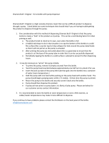
“Part Number: 9290312” October/22/2018 5
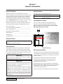
Read This Manual
Manitowoc Foodservice developed this manual as a
reference guide for the owner/operator and installer of this
equipment. Please read this manual before installation or
operation of the machine. A qualified service technician
must perform installation and start-up of this equipment.
Consult Section 4 within this manual for service assistance.
If you cannot correct the service problem, consult
Manitowoc KitchenCare at 1-844-724-CARE. Always have
your model and serial number available when you call.
Your Service Agent _______________________________
Service Agent Telephone Number ____________________
Your Local Distributor______________________________
Distributor Telephone Number ______________________
Model Number __________________________________
Serial Number ___________________________________
Installation Date _________________________________
About N
2
Fusion™
Class A: EMC Registration is done on this equipment for business
use only (Class A). Product seller and user should notice that this
equipment is not for household use.
Unit Inspection
Thoroughly inspect the unit upon delivery. Immediately
report any damage that occurred during transportation
to the delivery carrier. Request a written inspection report
from a claims inspector to document any necessary claim.
See “Warranty Information” on page 5.
n
Warning
Do not damage the refrigeration circuit when installing,
maintaining or servicing the unit.
n
Warning
Do not operate equipment that has been misused, abused,
neglected, damaged, or altered/modified from that of
original manufactured specifications.
This appliance is not intended for use by persons (including
children) with reduced physical, sensory or mental
capabilities, or lack of experience and knowledge, unless
they have been given supervision concerning use of the
appliance by a person responsible for their safety. Children
should be supervised to ensure that they do not play with
the appliance.
Model Numbers
This manual covers the following models:
N
2
Fusion™ Nitrogen Beverage Dispenser
ND21TS00, ND21TS01, ND21TS02, ND21TS03, ND21TS04,
ND21RS00, ND21RS02
Serial Number Location
The serial number on N2Fusion™ Nitrogen Beverage
Dispenser is printed on the left side of the interior wall.
Always have the serial number of your unit available
when calling for parts or service.
Sample Serial Tag
Warranty Information
Consult your local Service Agent or Representative for terms
and conditions of your warranty. Your warranty specifically
excludes all general adjustments, cleaning, accessories and
related servicing.
Your warranty card must be returned to activate the
warranty on this equipment. If a warranty card is not
returned, the warranty period can begin when the
equipment leaves the factory.
No equipment may be returned without a written Return
Materials Authorization (RMA). Equipment returned without
an RMA will be refused at the dock and returned to the
sender at the sender’s expense.
Please contact your local distributor for return procedures
Section 1
General Information

6 Part Number: 9290312 October/22/2018
General Information Section 1
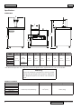
Specifications
DIMENSIONS
A
C
D
B
E
F
G
H
I
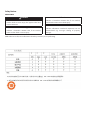
Model A B C D E F G H I
ND21TS00
27.3"
(69 cm)
34.0"
(86 cm)
28.4"
(72 cm)
20.7"
(53 cm)
13.6"
(35 cm)
16.1"
(41 cm)
44.6"
(113 cm)
10.6"
(27 cm)
7.3"
(19 cm)
ND21TS01
ND21TS02
ND21TS03
ND21TS04
ND21RS00 30.75"
(78 cm) *
ND21RS02
* This dimension represents units using 1.25" (3.175 cm) low profile casters, regular casters are 1.25" (3.175 cm) taller.
n
Warning
To avoid instability the installation area must be capable
of supporting the weight of the equipment. Additionally
the equipment must be level side to side and front to
back.
CAPACITY & WEIGHT
Model Max Capacity Volume Weight
ND21TS00
3 - 3 Gallon (11.36L) Coffee Kegs 5.7Ft
3
(161L) 168lbs (76kg)
ND21TS01
ND21TS02
ND21TS03
ND21TS04
ND21RS00
ND21RS02

Part Number: 9290312 October/22/2018 7
Section 1 General Information
PRODUCT DELIVERY LOCATION
n
Warning
This equipment must be positioned so that the plug is
accessible unless other means for disconnection from
the power supply (e.g., circuit breaker or disconnect
switch) is provided.
n
Warning
Adequate means must be provided to limit the
movement of this appliance without depending on or
transmitting stress to the electrical conduit or gas lines.
n
Warning
To avoid instability the installation area must be capable
of supporting the combined weight of the equipment
and product. Additionally the equipment must be level
side to side and front to back.
n
Warning
This equipment is intended for indoor use only. Do not
install or operate this equipment in outdoor areas.
n
Warning
Do not position the air intake vent near steam or heat
exhaust of another appliance.
The location selected for the equipment must meet the
following criteria. If any of these criteria are not met, select
another location.
• Units are intended for indoor use only.
• The location MUST be level both front to back and side to
side, stable and capable of supporting the weight of the
equipment.
• Position the equipment so it will not tip or slide.
• Recommended air temperature is 41° - 86°F (5° - 30°C), and
must not exceed 90°F (32°C), climate class 4.
• Location must have proper ventilation, DO NOT install in an
enclosure/enclosed cabinet with no access to ambient air.
• The location must not be near heat-generating equipment
or in direct sunlight and must be protected from weather.
• Verify floor of install location is within 1/2" (1.3 cm) of level
front to back, side to side.
• Keep equipment area clear of combustible material.
• Do not install the equipment directly over a drain. Steam
rising up out of the drain will adversely affect operation, air
circulation, and damage electrical /electronic components
• Do not install in an area where a high-pressure water jet
could be used for cleaning.
Clearances
DANGER
Minimum clearance requirements are the same for
noncombustible locations as for combustible locations.
The flooring under the appliance must be made of a
noncombustible material.
DANGER
Risk of fire/shock. All minimum clearances must be
maintained. Do not obstruct vents or openings..
Sides 0" (0 cm)
Back 3" (76 mm)
Front 30" (76 cm)
n
Warning
Do not obstruct machine vents or openings this includes
installing in an enclosed cabinet where the unit will not
have access to ambient air.
Heat of Rejection
Model BTU/hr
ND21TS00
1430 (0.42 kW)
ND21TS01
ND21TS02
ND21TS03
ND21TS04
ND21RS00
ND21RS02
REFRIGERANT CHARGE
Important
Due to continuous improvements, this information is for
reference only. Please refer to the serial number tag to
verify.
Model Type Refrigerant Charge
ND21TS00
R404A 7.0 oz (198g)
ND21TS01
ND21TS02
ND21TS03
ND21TS04
ND21RS00
ND21RS02

8 Part Number: 9290312 October/22/2018
General Information Section 1
ELECTRICAL
DANGER
Check all wiring connections, including factory
terminals, before operation. Connections can become
loose during shipment and installation.
n
Warning
If the supply cord is damaged, it must be replaced by a
special cord or assembly available from the manufacturer
or its service agent.
n
Warning
The machine must be wired and grounded in accordance
with national and local electrical codes.
Minimum Circuit Ampacity
The minimum circuit ampacity is used to help select the
wire size of the electrical supply. (Minimum circuit ampacity
is not the N
2
Fusion System’s running amp load.) The wire
size (or gauge) is also dependent upon location, materials
used, length of run, etc., it must be determined by a
qualified electrician.
Voltage
A dedicated electrical circuit is required, a power cord
is provided with all units. Some models are available in
different voltages and may be equipped with a different
plug.
The following precautions must be observed:
• The equipment must be grounded.
• A separate fuse/circuit breaker must be provided for
each unit.
• A qualified electrician must determine proper wire size
dependent upon location, materials used and length
of run (minimum circuit ampacity can be used to help
select the wire size).
• The maximum allowable voltage variation is ±10% of
the rated voltage at equipment start-up (when the
electrical load is highest).
• Check all green ground screws, cables and wire
connections to verify they are tight before start-up.
Minimum Circuit Amperage Chart
Important
Due to continuous improvements, this information is for
reference only. Please refer to the serial number tag to
verify.
Model Voltage/Cycle/Phase
Total
Amps
HP
Breaker
Size (Max)
ND21TS00
115/60/1 6.0 A
1/5 15 A
ND21RS00
ND21TS01 220/60/1 2.5 A
ND21TS02
220-230/50/1 2.5 A
ND21RS02
ND21TS03 100/60/1 6.0 A
ND21TS04 100/50/1 6.0 A
Preparing the power cord (International units only)
The following instructions cover the installation of a 220
VAC, 50/60 Hz (international) unit. An appropriate 3-wire
power receptacle must be located within 6 ft (1.8 m) of the
unit. Unpack the unit from its transportation packaging and
visually check for any signs of damage.
NOTE: Only use an approved plug for the country in which
the unit is being installed.
Important
The wires in the power cord/mains lead are colored in
accordance with the following code:
• Green / Yellow = Ground/Earth
• Blue = Neutral
• Brown = Line/Live
1. Locate a 3-terminal plug. This plug (not furnished with
unit) must have a ground-wire-connecting terminal.
2. Locate the loose end of the power cord attached to
the unit. All three (3) wires are stripped to 1/2" (1.3 cm)
length from the end.
3. Connect all three (3) wires to the plug using the
1/2" (1.3 cm) stripped ends or any other terminal
requirements. Different plugs and terminals may
require different stripped lengths.
4. Inspect the cord and plug connection for any loose or
bare wires.

Part Number: 9290312 October/22/2018 9
Section 1 General Information
Grounding Instructions
This appliance must be grounded/earthed. In the event
of malfunction or breakdown, grounding provides a
path of least resistance for electric current to reduce the
risk of electric shock. This appliance is equipped with a
cord having an equipment-grounding conductor and
a grounding plug. The plug must be plugged into an
appropriate outlet that is properly installed and grounded/
earthed in accordance with all local codes and ordinances.
Check with a qualified electrician or serviceman if the
grounding instructions are not completely understood or if
in doubt as to whether the product is properly grounded.
Do not modify the plug provided; if it will not fit the outlet,
have the proper outlet installed by a qualified electrician.
Do not use an extension cord or an adapter plug with this
equipment.
NOTE: For 220-240 VAC, 50/60 Hz International Units, a
ground male plug must be supplied at the installation of
the unit.
n
Warning
When using electric appliances, basic precautions must
always be followed, including the following:
A. Read all the instructions before using the
appliance.
B. To reduce the risk of injury, close supervision
is necessary when an appliance is used near
children.
C. Do not contact moving parts.
D. Only use attachments recommended or sold by
the manufacturer.
E. Do not use outdoors.
F. For a cord-connected appliance, the following
must be included:
• Do not unplug by pulling on cord. To unplug,
grasp the plug, not the cord.
• Unplug from outlet when not in use and
before servicing or cleaning.
• Do not operate any appliance with a
damaged cord or plug, or after the appliance
malfunctions or is dropped or damaged in
any manner. Contact the nearest authorized
service facility for examination, repair, or
electrical or mechanical adjustment.
G. Follow applicable lock out tag out procedures
before working on equipment.
H. Connect to a properly grounded outlet only. See
Grounding Instructions.


Part Number: 9290312 October/22/2018 11
Step-by-Step Installation
These instructions are provided to assist the qualified installer. Contact your Manitowoc Foodservice Service Agent or call
Manitowoc Foodservice for information regarding start-up services.
DANGER
Use appropriate safety equipment during installation
and servicing.
DANGER
Installation must comply with all applicable fire and
health codes in your jurisdiction.
n
Warning
Remove all removable panels before lifting and installing.
n
Warning
Do not damage the refrigeration circuit when installing,
maintaining or servicing the unit.
Important
All plumbing must conform to local, state and national
codes.
Important
Failure to follow these installation guidelines may affect
warranty coverage.
PREINSTALLATION CHECKLIST
Any damage should be noted and reported to the
delivering carrier immediately.
Check the lower portion of the unit to be sure
casters are not bent.
Visually inspect the refrigeration package,
compressor compartment housing. Be sure lines
are secure and base is still intact.
Inspect installation location behind the unit for
electrical outlet location and Nitrogen (N
2
).
Power unit up by plugging into power source.
Check for correct voltage at outlet dedicated for
the Nitrogen Beverage Dispenser.
Verify floor of install location is within 1/2" (1.3 cm)
of level front to back, side to side and all casters are
touching the floor.
n
Warning
The mass of this appliance will allow it to move
uncontrolled on an inclined surface. Adequate means
must be provided to prevent uncontrolled movement
at all times.
Check that internal connections are secure and did
not vibrate loose during shipment.
Installation location has proper ventilation where
unit has access to ambient air.
Section 2
Installation

12 Part Number: 9290312 October/22/2018
Installation Section 2
REMOTE TOWER INSTALLATION
These instructions are only for units that require remote
placement of the dispensing tower. If this is a self contained
unit with out remote setup continue to “Nitrogen Regulator
& Tank Assembly” on page 13.
Checklist
Tower location should be no more than 20.70"
(53 cm) from edge of the counter.
Mount tower within 6 linear ft (1.83 m) from side of
base cabinet.
Make sure location has space for the drip tray
shipped with the unit.
NOTE: Drip trays equipped with a drain are also available
but are not standard equipment.
Location
1. Identify the counter top location for the tower making
sure there is room for the drip tray, conduit routing
under the counter, and is away from any heat source.
Important
If the drip tray is equipped with a drain make sure install
location is near a floor drain.
2. Using the provided counter top template mark where
the 2" (5 cm) conduit and tower mount screw holes will
be drilled.
3. Cut and drill holes in the counter using the markings.
NOTE: Drip trays equipped with a drain will need a 7/8"
(2.22 cm) hole drilled into the counter using the provided
template for routing to a floor drain.
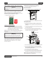
Mounting & Routing
Important
Make sure the rubber counter top gasket is in place on
the tower before routing conduit and mounting tower.
To Cabinet
TAP #1
Plain
TAP #2
Nitro/Gas
4. Route conduit from the tower down through the 2in
(5 cm) hole and mount the tower to the counter top
with the provided plate and screws.
NOTE: Make sure the rubber gasket is properly seated on
the tower and seals to the counter top.
5. Run the conduit from the tower to the N
2
Fusion™ cabinet.
6. Remove the two (2) screws from the solenoid cover
mounted to the inside top of the cabinet to gain access
to solenoids 1 and 2.
7. Route tubing through the top of the cabinet and attach
to the corresponding solenoids.
NOTE: Tubing already routed to the solenoids in the cabinet
should be marked with yellow 1 & 2 stickers.
n
Warning
Do not add line to the conduit this can cause poor drink
quality and the unit may not perform properly.

Part Number: 9290312 October/22/2018 13
Section 2 Installation
Important
Allow four (4)ft (1.22m) of tubing for a service loop to
allow the cabinet to be pulled out during service and
cleaning. Cut off extra tubing if needed.
8. Once connections have been made put the solenoid
cover back into place.
Drip tray
9. Place drip tray or drain pan in proper location lined up
below the dispensing taps.
Important
Drip trays equipped with a drain need to be sealed to
the counter top, be sure to follow all local codes.
NITROGEN REGULATOR & TANK ASSEMBLY
DANGER
Tank under high pressure. Do not drop or allow tank to
fall over. Tank must be chained and secured to prevent
movement as per OSHA requirements. Do not attempt to
handle or connect to tank unless properly trained.
NITROGEN IS AN ASPHYXIANT GAS. A LEAK IN AN
ENCLOSED AREA COULD DISPLACE OXYGEN AND CAUSE
ASPHYXIATION. ALWAYS TEST GAS HANDLING SYSTEMS
FOR LEAKS. A N2 GAS DETECTOR IS RECOMMENDED.
Nitrogen cylinders contain high-pressure gas which can
be hazardous if not handled properly. Make sure you READ
and UNDERSTAND the following procedures for nitrogen
cylinders BEFORE installation.
Important
Use only food grade nitrogen (99.5% pure).
1. ALWAYS connect the nitrogen cylinder to the primary
regulator and NEVER directly to the unit, keg, or
dispensing system. Failure to do so could result in
an explosion with possible death or injury when the
cylinder valve is opened.
2. ALWAYS follow correct procedures when cylinders are
changed.
3. ALWAYS secure the cylinder in an upright position with
a chain.
4. NEVER drop or throw a nitrogen cylinder.
5. ALWAYS keep a nitrogen cylinder away from heat.
Store extra cylinders in a cool place (preferably 70°F).
Securely fasten with a chain in an upright position
when storing.
6. ALWAYS check the D.O.T. test date on the cylinder neck
before installation. Ask your gas supplier for D.O.T. test
requirements.
7. NEVER connect a product container unless there is
a safety in the pressure system at or on the nitrogen
regulator.
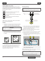
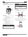
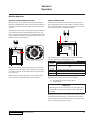
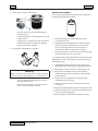
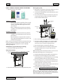
NITROGEN INSTALLATION/REPLACEMENT
NOTE: During initial installation of the unit a bracket for the
nitrogen cylinder must be installed to solid wall nearby and
a chain used to secure it to the bracket.
n
Warning
Verify gauge orientation
before setting pressures!
C
E
B
D
A
NITROGEN
NITROGEN
INTEGRAL SAFETY
DEVICE
TO PRODUCT
CONTAINER
1. Make sure cylinder valve “A” is closed.
2. Unscrew (counter clockwise) regulator key “B” as far out
as it will go. (The regulator is now in the off position.)
3. Remove regulator from empty cylinder at “D”.
4. Remove dust cap from new cylinder at “D”. Open and
close valve “A” quickly to blow dust from outlet.
5. With cylinder valve “A” in closed position, re-attach
regulator to cylinder at “D”.
6. Open valve “A” all the way. (This is important because
this cylinder valve seals in two places.)
7. Screw regulator key “B” in (clockwise) until required
pressure is reached “E”.
NOTE: Drinks will not pour if outlet valve “A” is closed.

14 Part Number: 9290312 October/22/2018
Installation Section 2
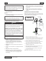
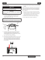
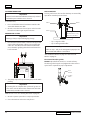
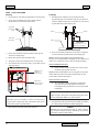
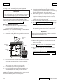
NITROGEN CONNECTIONS & PRESSURES
1. Set inlet from food grade nitrogen tank to back of the
dispenser to 85 - 90 psi
(.586 - .621 MPa, 586 - 621 kPa, 5.86 - 6.21 bar).
Line OUT
Pressure to Unit
Line IN
N Tank Pressure
n
Warning
Line Out Pressure
Do Not exceed 90 psi
(.621 MPa, 621 kPa, 6.21 bar)
to the unit!
N
2
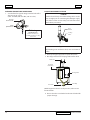
QUICK DISCONNECT & DRAIN
,
Caution
Installer should always check the locking collars on the
taps are tight prior to connecting the Nitrogen supply
line. If these collars are loose they can leak at the tower
shank when pressurized.
Flow
Control
Locking
Collar
Important
All plumbing must conform to local, state and national
codes.
2. Hook up nitrogen supply line to quick disconnect.
3. Run drip pan drain line and purge tube to floor drain.
N
2
Supply
Connection
Drain Line
Floor Drain
N
2
Purge Tube
2" Air Gap
NOTE: Purge tube releases under pressure, make sure it is
fastened down.
4. Ensure drain line is not kinked or otherwise blocked for
proper drainage.

Part Number: 9290312 October/22/2018 15
Section 2 Installation
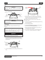
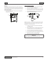
KEG & PUMP REGULATORS
5. Once the nitrogen line is hooked up to the unit check the
pressures on the two (2) regulators located in the back of
the unit.
Regulator 1
Keg
Regulator 2
Nitrogenator
For 60Hz machines
6. Verify or set Regulator 1- Nitrogen Supply to Coffee Keg.
• Set to 16 psi +/- 2 psi
(.110 MPa, 110 kPa, 1.10 bar).
7. Verify or set Regulator 2- Nitrogen Supply to Nitrogenator.
• Set to 34 psi +/- 2 psi
(.234 MPa, 234 kPa, 2.34 bar).
For 50Hz machines
8. Verify or set Regulator 1- Nitrogen Supply to Coffee Keg.
• Set to 22 psi +/- 2 psi
(.152 MPa, 152 kPa, 1.52 bar).
9. Verify or set Regulator 2- Nitrogen Supply to Nitrogenator.
• Set to 44 psi +/- 2 psi
(.303 MPa, 303 kPa, 3.03 bar).
If adjustments are needed the installer or technician will
need to remove the rear cover to access the regulators.
DANGER
ELECTRICAL SHOCK HAZARD! The power supply is
located in the upper right behind the cover and has live
heat sinks. Unplug from power source when removing
cover.
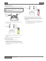
KEG CONNECTIONS
DANGER
Never stand directly over keg when connecting,
disconnecting, or when keg is pressurized.
Important
Only use AEB Kegs. Available from Manitowoc
FoodService.
Keg Post Collars
1. Locate post collars and match the black to OUT post
and gray to IN post.
Black collar on
OUT connection
of each keg
Gray collar on
IN connection
of each keg
NOTE: Color coding allows partners to match the black
connector to black collar and gray connector to gray collar.
2. Press each collar over the IN and OUT posts until they
seat in the grove below the taper.
Collar Groove

16 Part Number: 9290312 October/22/2018
Installation Section 2
Connecting the Keg
DANGER
Never stand directly over keg when connecting,
disconnecting, or when keg is pressurized.
Important
Only use AEB Kegs. Available from Manitowoc
Foodservice.
3. First connect the Black quick connect line to the
connection labeled OUT on the coffee keg. This
supplies coffee to Tap 1 and 2.
Important
Hook the OUT line up to the coffee keg first, this helps prime
the system once the nitrogen IN line is connected to the tank.
Pull ring
while
connecting
to post then
release to
lock into
place.
4. Connect the Gray quick connect line second to the
connection labeled IN on the coffee keg. This line
supplies Nitrogen into tank. See “Keg Change” on page
21 & “Priming the System” on page 20
5. The system is now ready to be primed.
6. Press the Prime/Clean button, located in the upper left
corner of the refrigeration cabinet, once to prime the
coffee line. The LED around the button will flash ON
once, then OFF signifying that the Prime function has
been activated.
7. The pump may run for up to twenty (20) seconds while
priming.
NOTE: If priming fails to complete the system will go into
an error state and the Prime/Clean button LED will blink
continuously until the error is cleared. See “Clearing Error
Code” on page 20
8. Once the system is primed it is ready to pour drinks.
9. Check the regulators to make sure the pressures have
not changed and pour a few drinks from each tap to
verify proper flow. Adjust pressures if needed.
10. Check for leaks inside the cabinet and at the taps.
11. Close cabinet door and unit is ready for use.

Part Number: 9290312 October/22/2018 17
Section 2 Installation
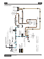
PLUMBING DIAGRAM
PRIMARY REGULATOR
85-90 psi
(.586 - .621 MPa, 586 - 621 kPa, 5.86 - 6.21 bar)
DO NOT EXCEED 90 PSI (621 MPa, 621 kPa, 6.21 bar)
SUPPLY TANK
REGULATOR
PRESSURE
SWITCH
NITROGEN
COFFEE
NITRO COFFEE
DRAIN
KEG
LDD
LIQUID
DETECTION
DEVICE
SENSOR
SOLENOID
VALVE
SOLENOID
VALVE
TAP 1
PLAIN
COFFEE
TAP 2
NITRO
COFFEE
FILTER/STRAINER
PUMP
N
NITROGENATOR
TANK
NITROGENATED
COFFEE OUT
TO TAP 2
PLAIN CHILLED
COFFEE TO
NITROGENATOR
PLAIN CHILLED COFFEE
PLAIN CHILLED COFFEE TO TAP 1
PRV
PRESSURE RELIEF VALVE
REGULATOR 1 *
N SUPPLY TO COFFEE KEG
16 psi +/- 2
(.110 MPa, 110 kPa, 1.10 bar)
REGULATOR 2 **
N SUPPLY TO
NITROGENATOR
34 psi +/- 2
(.234 MPa, 234 kPa, 2.34 bar)
* Regulator 1 on 50Hz Units
22 psi +/- 2 psi
(.152 MPa, 152 kPa, 1.52 bar)
** Regulator 2 on 50Hz Units
44 psi +/- 2 psi
(.303 MPa, 303 kPa, 3.03 bar)
N
SUPPLY
TANK

18 Part Number: 9290312 October/22/2018
Installation Section 2
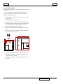
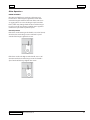
DOOR HINGE REVERSAL
Instructions for installations that require the cabinet door to
be reversed.
1. Use a screwdriver to remove the bottom hinge pin.
NOTE: Lock-tight was used during factory installation, so
extra force may be required.
2. Tilt door out from bottom and slide top pin out of the
hinge bracket.
3. Remove top hinge pin from door.
4. Use a putty knife or similar tool to remove both plugs
from door to expose alternate hinge pin locations and
re-install the plugs in original hinge pin locations.
5. Install top hinge pin on new hinge side.
6. Remove top and bottom hinge brackets from cabinet
face.
7. Locate etch marks on the opposite side of cabinet face
and drill 1/8" (0.3175 cm) holes.
8. Install top and bottom hinge brackets in new locations.
9. Slide top door hinge pin into top hinge bracket and
close door onto cabinet face.
10. Install bottom hinge pin through hinge bracket and
into door.

Part Number: 9290312 October/22/2018 19
Machine Operation
CONTROLS/PROGRAMMING/SETTINGS
After the unit is connected to power it will automatically
begin operating. With the doors closed, the temperature of
the cabinet should reach 36°F to 40°F (2°C to 4°C) in about
one hour.
A thermostat located in the evaporator housing on interior
rear of the unit, controls the temperature in the unit. The
factory setting for the control is 4 and maintains about 38°F
(3°C) in the box. Set toward 1 for higher temperatures and
toward 7 for lower temperatures.
Refrigerators defrost automatically with every cycle of the
compressor. The water generated is routed to a pan on the
rear of the unit and is evaporated by the heat given off by
the compressor.
NOTE: During normal operation the evaporator fan may
cycle and/or pulse independently of the compressor.
PRIME / CLEAN BUTTON
The Prime/Clean button is located in the upper left corner
of the refrigeration cabinet. This button is used for priming
the system with coffee, cleaning, and displaying error codes
using the blue LED ring around the button.
The following table lists the Prime/Clean Button functions
and state the LED is in during each mode.
PRIME /CLEAN BUTTON FUNCTIONS
Mode LED
Dispense
and/or Keg
Change
OFF
Prime Blinks once then OFF when button is pressed
Cleaning ON constant after button pressed and held
Error Blinks constantly
NOTE: Error mode can be caused by the following;
A. Keg Needs Primed or Failed to Prime
B. Keg is Empty
Important
DO NOT put unit into cleaning mode with coffee keg
connected! This empty the keg and pump coffee down
the drain!
NOTE: If cleaning mode is accidentally entered with a coffee
keg attached immediately press and hold the Prime/Clean
button until the LED turns OFF. Priming may be required to
put the unit back into dispense mode.
Section 3
Operation

20 Part Number: 9290312 October/22/2018
Operation Section 3
CLEARING ERROR CODE
Important
Prime/Clean button LED will blink continuously and unit
will not dispense until the error is cleared.
To clear the error;
1. Press and hold the Prime/Clean button until the LED
around the button turns OFF.
2. Once the error has been cleared, press and release the
Prime/Clean button again to prime the unit.
PRIMING THE SYSTEM
Important
Priming is always required during keg change.
1. Press the Prime/Clean button, located in the upper left
corner of the refrigeration cabinet, once to prime the
coffee line. The LED around the button will flash ON
once, then OFF signifying that the Prime function has
been activated.
2. The pump may run for up to twenty (20) seconds while
priming.
Important
If priming fails to complete the system will go into an
error state and the Prime/Clean button LED will blink
continuously until the error is cleared.
NOTE: If error occurs See “Clearing Error Code” on page 20
3. Once the system is primed it is ready to pour drinks.
4. Close cabinet door and unit is ready for use.
TAPS & NOZZLES
For best performance do not allow both taps to remain fully
opened for extended periods of time.
TAP #1
Surface
TAP #2
Important
TAP #2 Contains an o-ring,
diffuser disc, and diffuser.
• Tap 1 - Regular Coffee
• Tap 2 - Nitrogenated Coffee
Important
Coffee on tap 2 will not be nitrogenated properly if the
correct nozzle with diffuser is not installed.
“How to Remove Nozzles” on page 26 & “How to Install
Nozzles” on page 26
Flow Control & Locking Collar
DO NOT adjust the flow control, it is set at the factory.
The locking collar keeps the tap tightened to the tower. A
special tool is required for proper adjustment.
Flow
Control
Locking
Collar
Page is loading ...
Page is loading ...
Page is loading ...
Page is loading ...
Page is loading ...
Page is loading ...
Page is loading ...
Page is loading ...
Page is loading ...
Page is loading ...
Page is loading ...
Page is loading ...
Page is loading ...
Page is loading ...
Page is loading ...
Page is loading ...
Page is loading ...
Page is loading ...
Page is loading ...
Page is loading ...
Page is loading ...
Page is loading ...
Page is loading ...
Page is loading ...
-
 1
1
-
 2
2
-
 3
3
-
 4
4
-
 5
5
-
 6
6
-
 7
7
-
 8
8
-
 9
9
-
 10
10
-
 11
11
-
 12
12
-
 13
13
-
 14
14
-
 15
15
-
 16
16
-
 17
17
-
 18
18
-
 19
19
-
 20
20
-
 21
21
-
 22
22
-
 23
23
-
 24
24
-
 25
25
-
 26
26
-
 27
27
-
 28
28
-
 29
29
-
 30
30
-
 31
31
-
 32
32
-
 33
33
-
 34
34
-
 35
35
-
 36
36
-
 37
37
-
 38
38
-
 39
39
-
 40
40
-
 41
41
-
 42
42
-
 43
43
-
 44
44


MULTIPLEX N2-Fusion ND21RS00 Installation, Operation & Maintenance Manual
- Category
- Coffee makers
- Type
- Installation, Operation & Maintenance Manual
Ask a question and I''ll find the answer in the document
Finding information in a document is now easier with AI
Related papers
-
MULTIPLEX N2Fusion Nitrogen Beverage Dispenser User manual
-
-
 KitchenCare N2Fusion™ 2.0E Nitrogen Beverage System Owner Instruction Manual
-
-
MULTIPLEX Blend-In-Cup MA-8-2AF Installation, Operation and Maintenance Manual
-
-
-
-
-
Manitowoc Beverage Systems Multiplex FreshBlender User manual

Other documents
-
T & S Brass & Bronze Works 5HR-242-01-GH Datasheet
-
Summit SBC635MCMTWIN User manual
-
-
Danby DBD5L User manual
-
Igloo BTC511 User manual
-
 Chamois Butt'r Original Anti-Chafe Cream, 32 oz Bottle User guide
-
Philips HD3620/25 User manual
-
Philips HD3610/50 User manual
-
Hendi 274149 User manual
-
