Page is loading ...

iNSTALLATiON AND SERVICE MUST BE PERFORMED BY
A QUALiFiED iNSTALLER.
iMPORTANT: SAVE FOR LOCAL ELECTRICAL iNSPECTOR'S USE.
READ AND SAVE THESE iNSTRUCTiONS FOR FUTURE REFERENCE.
If the information in this manual is not followed exactly, a fire or explosion may result
causing property damage, personal injury or death.
FOR YOUR SAFETY:
-- Do not store or use gasoline or other flammable vapors and liquids in the vicinity of this or any other
appliance.
-- WHAT TO DO IF YOU SMELL GAS:
* Do not try to light any appliance.
* Do not touch any electrical switch; do not use any phone in your building.
* Immediately call your gas supplier from a neighbor's phone. Follow the gas supplier's instructions.
* If you cannot reach your gas supplier, call the fire department.
-- Installation and service must be performed by a qualified installer, service agency or the gas supplier.
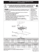
Cooktop Dimensions
30" Min.
Cooktop Cutout Dimensions
Figure I
26" Model 25 3A" 21 9/16" 3 1/2" 25" 25" 20 1/2" 20 1/2"
30" Model 30" 21 1/2" 3 1/8" 26 5/8" 26 7/8" 19" 193/8"
36" Model 36" 18 5/8" 3 ¼" 34 ¼" 34 3/8" 16 5/8" 16 3A"
NOTE: Wiring diagrams for these appliances are enclosed in this booklet.
Printedin Canada
P/N318201452 (1302) Rev.H
English - pages 1-10
Espahol- p_iginas 11-22
Wiring Diagram - pages 24

13" Max. Depth
For Cabinet
Installed Above
Cooktop.
18" Min.
Dimensions J isthe Minimum
Distance Required Between
Rearof Top Panel to Adjacent
Combustible Surfaces.
30" Min. Clearance
Between the Top
of the Cooking
Platform and
---------_ #U nprotected Wood
or Metal
Cabinet
Clearance
Dimension K isthe
Minimum Clearance
Required From Left
Side of Top Panel to
Adjacent Combustible
Surface.
Dimension H isthe
Minimum Clearance
Required From Right
Side of Top Panelto
Adjacent Combustible
Surface.
Allow Dimension L Space Below
Cooktop for Piping and Electrical
Connections.
To eliminate the risk of
burns or fire by reaching over heated
surfaces, cabinet storage space located
above the cooktop should be avoided. If
cabinet storage is provided, risk can be
reduced by installing a range hood that
projects horizontally a minimum of 5"
beyond the bottom of the cabinets.
Note: (For 26" and 36" Models Only). The rear edge of opening
must be 1 1/2"from rearface of base cabinet. If countertops are
ordered from a supplier other than cabinet supplier, the relation of
the cutout in relation to the rear of the cabinet shall be specified.
26" Model 1" 1/£ 1" 81/£
30" Model 0" 2" 2" 8 1/8"
36" Model 1" 21/2'' 1" 8W'
Figure 2 - COUNTERTOP CUTOUT OPENING
2

Important Notes to the Installer
1. Read all instructions contained in these installation
instructions before installing the cooktop.
2. Remove all packing material before connecting the
electrical supply to the cooktop.
3. Observe all governing codes and ordinances.
4. Be sure to leave these instructions with the consumer.
5. Note: For operation at 2000 ft. elevations above see
level, appliance rating shall be reduced by 4 percent
for each additional 1000 ft.
Important Note to the Consumer
Keep these instructions with your Use and Care Guide for
future reference.
IMPORTANT SAFETY
INSTRUCTIONS
Installation of these cooktops must conform with local
codes or, in the absence of local codes, with the National
Fuel Gas Code ANSI Z223.1--1atest edition.
These cooktops has been design certified by American
Gas Association (A.G.A.). As with any appliance using
gas and generating heat, there are certain safety
precautions you should follow. You will find them in the
Use and Care Guide read it carefully.
• Be sure your cooktop is installed and grounded
properly by a qualified installer or service
technician.
• These cooktops must be electrically grounded in
accordance with local codes or, in their absence,
with the National Electrical Code ANSI/NFPA No.
70--latest edition. See grounding instructions
farther in this manual.
The installation of appliances designed for
manufactured (mobile) home installation must
conform with Manufactured Home Construction
and Safety Standard Title 24CFR, Part 3280
[Formerly the Federal Standard for Mobile Home
Construction and Safety, Title 24, HUD, (Part
280)] or when such standard is not applicable the
Standard for Manufactured Home Installation
1982 (Manufactured Home Sites, Communities
and Set-Ups), ANSI Z225.1/NFPA 501-A- latest
edition, or with local codes.
• Air curtain or other overhead hoods, which operate
by blowing a downward air flow on to a range, shall
not be used in conjunction with gas ranges other
than when the hood and range have been designed,
tested and listen by an independent test laboratory
for use in combination with each other.
• Do not store items of interest to children in the
cabinets above the cooktop. Children could be
seriously burned climbing on the cooktop to reach
items.
To eliminate the need to reach over the surface
burners, cabinet storage space above the burners
should be avoided.
Adjust surface burner flame size so it does not
extend beyond the edge of the cooking utensil.
Excessiveflame is hazardous.
Never use your cooktop for warming or heating
the room. Prolonged use of the cooktop without
adequate ventilation can be hazardous.
Do not store or use gasoline or other flammable
vapors and liquids near this or any other
appliance. Explosions or fires could result.
The electrical power to the cooktop
must be shut off while line connections are being
made. Failure to do so could result in serious injury
or death,
Safety Tips - Gas Surface Units
Your new cooktop has been tested to meet the most
rigid safety standards. You can feel confident while
using it but use these safety suggestions to help avoid
accidents that can cause injury to the user or damage to
the cooktop.
Note: All safety tips listed may not apply to your model.
Plug the unit into a 120-volt grounded outlet only.
Do not remove the grounding prong from the plug. If
in doubt about the grounding of the home electrical
system, it isthe personal responsibility and obligation
of the owner to contact a qualified electrician and
have an ungrounded receptacle replaced by a properly
grounded three-prong wall receptacle, in accordance
with the National Electrical Code. Do not use an
extension cord with this unit.
Do not repair or replace any part of the unit unless
specifically recommended in this guide. Call a qualified
technician for all other servicing.
Clean only the parts of the cooktop as instructed in
the Use and Care Guide.
Be certain all packing materials are removed from
the unit before operating to prevent fire or smoke
damage, should the packing material ignite.
Ventilating Hoods
• Clean ventilating hood frequently. Grease should not
be allowed to accumulate on hood or filter.
When flaming foods under the hood turn the fan off.
The fan, if operating, may spread the flame.
3

Safety on the Cooktop
• Do not allow dry empty pans to cook on the cooktop
as this could ruin the pan and cause a fire hazard.
Do not use a wok on the cooking surface if it is
equipped with a round metal support placed over the
burner grate. This support acts as a heat trap which
may damage the burner grate, spillover bows and
burner head. It may also cause the burner to work
improperly and create a carbon monoxide level above
current standards resulting in a over adjacent burners.
When lowering the cooktop be careful not to pinch
your fingers. Grasp sides of the top with fingertips and
lower into position.
Important: Please Read Before Continuing
These appliances and its individual shutoff valve must be
disconnected from the gas supply piping system during
any pressure testing of that system exceeding 1/2psig.
These appliances must be isolated from the gas supply
pipping system by closing its individual manual shutoff
valve during any pressure testing of the gas supply piping
system equal to or less than 1/2psig.
To avoid pilot outage (if applicable) close all openings
in the cabinet cavity that enclose this unit. Any opening
around gas service outlets must also be closed at the
time of installation.
These cooktops are not approved for use
with downdraft systems.
Disconnect the electrical supply before
servicing cooktops.
1. Wall Outlet Location
(some models)
i j
' U 10"
i
_ Recommendeiiiiiiiiiii!ii!_i!iii_i!iiiiill i_
: 120V grounded outlet
i on rear wall
CL of wall 22"
and unit
i
I
/
NOTE: If an outlet : |
is not available, i
have one installed '
i
by a qualified I
technician.
"CL of floor
26, Models 30" Models 36, Models
Dimension A 12 Y2" 12" 17 1/8"
Figure 3
1 Secure the Unit
A. 26" and 36" Cooktops
The unit must be secure in place. Remove the burner
grates and burner pans. The top may then be raised
after removing the knobs and by lifting along the
front edge of the top. Holes are provided in the front
and rear of the burner box to secure the unit to the
cabinet (see figure 4).
Cooktop Countertop
'_ ::_Wood Screw
_, (Not Provided)
Burner Box
Figure 4
4

B. 30" Cooktops
Unit Clam Down information
Once the cooktop is installed in the counter opening,
you must clamp the unit down as shown.
To clamp down, insert the bracket with the offset
side of the angle into the slots on each side of the
unit. The thumb screw should then be run through
the bracket, up against the bottom of the counter.
Tighten until the unit draws down (figure 5).
Cooktop Countertop
Angle Bracket
Screw
P
Burner Box Figure 5
2.1. Release the Burners
Once the cooktop is installed in the counter opening,
as shown in the previous steps, raise the cooktop
surface. 4 screws per pair of burners have been
installed to help solidify the unit during the transport.
Unscrew these 4 screws until the burners are at their
proper location (figure 6).
3. Provide an Adequate Gas Supply
The cooktops covered in these instructions are designed
to operate on natural gas at 4" of manifold pressure or
on LPgas at 10" of manifold pressure.
A convertible pressure regulator is supplied with each
surface unit and MUST BE CONNECTED IN SERIES
between the supply line and the valve manifold
regardless of which type of gas is being used.
The convertible regulator for the surface units must be
located and turned in such manner to allow for easy
access to the convertible feature.
For proper operation, the maximum inlet pressure
to the regulator must not exceed 14" of water column
(W.C.) pressure for both LPand Natural Gas.
For checking the regulator, the inlet pressure must be at
least 1" (or 2.5 kPa) greater than the regulator manifold
pressure setting. If the regulator is set for 4" of manifold
pressure, the inlet pressure must be at least 5". If the
regulator is set for 10", the inlet pressure must be at
least 11 ".
A manual shut-off valve must be installed on the gas
supply line, external to the unit and where it can be
easily reached for the purpose of turning the gas to the
unit on and off.
The gas supply line to the cooktops should be 1/2" or 3A"
pipe.
Seal all openings in the wall behind the cooktop and
in the floor under the cooktop after gas supply line is
installed.
Figure 6
5

4. Connection to gas
A. 26" Cooktop (seefigure 7)
Cooktop% Coupling
Box _ _ "'_,/J s_tl
Manifold Pipe
/ 1/2"Nipple
/
Pressure Regulator
Adaptor or Union_'J_ _
__ External
Shut-off Valve
Figure 7
Hookup the cooktop to the gas supply line.
Install the pressure regulator with the arrow pointing
toward cooktop and where you can reach the access
cap. Be sure you know how and where to shut off the
gas supply to the cooktop.
Leak testing of the appliance shall be conducted
according to the manufacturer's instructions.
Check for leaks. After connecting cooktop gas, check
system for leaks with a manometer. If a manometer is
not available shut all pilots off, turn the gas supply on
the unit and use a liquid leak detector at all joints and
connections to check for leaks.
Tighten all connections if necessary to prevent gas
leakage in the cooktop or supply line.
Check alignment of valves after connecting the
cooktop to the gas supply to be sure the manifold pipe
has not been moved. A misalignment could cause the
valve knob stem to rub on the control panel, resulting in
a gas leak at the valve.
IMPORTANT: A pipe joint sealant resistant to the action
of LP Gas must be used on all pipe connections.
B. 30" and 36" Cooktops (see figure 8)
Cooktop
r
Box -:: ,' ._ 1/2"Coupling
..... , (36" Cooktops Only)
X ppPressure : 1:,, Ni le
Regulator_,,,_ _
Adaptor or Union
IMPORTANT: Remove all packing material and literature
from cooktop before connecting gas and electrical
supply to the appliance.
Do not use flame to check for leaks from
gas connections. Checking for leaks with a flame may
result in a fire or explosion.
Disconnect the cooktop and its individual shutoff
valve from the gas supply piping system during any
pressure test greater than 1/2psig.
Isolate the cooktop from the gas supply piping
system by closing its individual manual shutoff valve
during any pressure testing of the gas supply piping
system at test pressures equal to or less than 1/2psig.
Shut-off
Figure 8
6

5. LP/Propane Gas Conversion
A. Pressure Regulator Conversion
IMPORTANT: Except for Puerto Rico 30" model all
cooktops are shipped from the factory set for use with
Natural Gas. Please verify the serial plate.
_'_ Cap
Plunger- Enlarged ,_
end UP for Natural H
Gas O
Note: • Do not remove the Pressure Regulator.
If in doubt about the pressure at the manifold,
use a manometer. The inlet pressure on the
regulator must be at least 1" W.C. higher
than the outlet pressure. Inlet pressure on the
regulator must never exceed 14" W.C.
Figure 10
Natural Gas
1. Convert the Pressure Regulator from Natural
Gas to LP Gas (see figure 9)
A. Remove the cap from the pressure regulator.
B. Remove the plunger.
C. Turn the plunger upside down with the
enlarge end DOWN.
D. Replace the plunger inside the regulator. The
letters LPor 10" W.C. should be visible on the
exposed end of the plunger.
E. Replace the cap on the pressure regulator.
2. Convert the Pressure Regulator from LP Gas
to NATURAL Gas (see figure 10)
Plunger- Enlarged _'_ Cap
end DOWN for LP "_ I_
Gas
Figure 9
LP Gas
A. Remove the cap from the pressure regulator.
B. Remove the plunger.
C. Turn the plunger upside down with the
enlarge end UP.
D. Replace the plunger inside the regulator. The
letters NAT or 4" W.C. should be visible on
the exposed end of the plunger.
E. Replace the cap on the pressure regulator.
B_ Burner Valves Conversion
(see figure 11 and 12)
j j J"
jJ
Figure 11
1. Remove valve knobs, top grates, burner pans
and lift cooktop to gain access to valves. Locate
valve hoods (orifices) on back side of valves.
2a. To convert burner valves from Natural Gas
to LP Gas, turn valve hoods (orifices) down until
snug against the mixer pin (approximately 2 1/2
turns). Do not overtighten,
2b. To convert burner valves from LP Gas to
Natural Gas, turn valve hoods (orifices) up until
it is away from the mixer pin (approximately 2 1/2
turns).
3. Apply gas to the burner and adjust pilots and air
shutter on burner venturi tube to proper flame
(refer to pictures in "Burner Flame Adjustment"
section for comparison).
Pin Hood
Natural Gas
Gas
Figure 12
7

6. Adjustments
A. Top Pilots Adjustment (Some models)
1. Remove valve knobs, top grates and burner
pans.
2. Lift top and prop up with support rod located in
the burner box.
3. Follow pilot tubes to their source on manifold
pipe and locate filter/pilot adjusting assembly.
4. Light two top pilots with match as shown in
figure 13.
If the air shutter needs adjusting, rotate the shutter to
allow more or less air to the burner tubes as needed.
For Natural Gas it may be necessary to rotate the air
shutter to some point less than half open for normal
flame; for LP Gas it may be necessary to rotate the air
shutter to a nearly full open setting for a normal flame.
C. Burner Flame Adjustment
1. Proper Air Adjustment (figure 16)
If the air shutter is properly adjusted, flame will be
steady, relatively quiet, and will have approximately
1/2"sharp blue cones. With LP gas, this usually occurs
when shutters are halfway open.
,
Figure 13
Adjust pilot flame between 1/8" and 1/4"(see
figure 14) so that a slight tinge of yellow appears
at the top.
Pilot flame
1/4"max. total height
Figure 14
Figure 16
2. Too Much Air (figure 17)
If the air shutter is adjusted so that too much
air flows into the burner, the flame will appear
unsteady, will possibly not burn all the way around,
and will be noisy (like a blowtorch).
B. Burner Air Shutter Adjustment
The air shutter adjustment for each of the four burners
is located at the open end of the venturi tube and sets
on the valve hood. Depending on the model, the shutter
is either held in place by friction fit or with Phillips head
screw.
Figure 17
3. Not Enough Air (figure 18)
If the air to the burner is insufficient, you will not see
any sharp blue cones in flame. The flame may burn
with yellow tips, and soot will accumulate on utensils
used on the burner.
Air Shutter
Figure 15
Figure 18
8

7. Connect Electricity to Gas Cooktop
Electrical Requirements
120 volt, 60 Hertz, properly grounded branch circuit
protected by a 15 amp circuit breaker or time delay fuse.
Do not use an extension cord with these cooktops.
IMPORTANT Pleaseread carefully.
For personal safety, these appliances must be
properly grounded.
The power cord of these appliances is equipped with a
3-prong (grounding) plug which mates with a standard
3-prong grounding wall receptacle (see Figure 19) to
minimize the possibility of electric shock hazard from this
appliance.
The wall receptacle and circuit should be checked by
a qualified electrician to make sure the receptacle is
properly grounded.
Note: All hookups and adjustment shall be performed by
qualified technicians.
Situations where appliance power cord will be
disconnected frequently. Do not use an adaptor plug
in these situations because disconnecting of the power
cord places undue strain on the adaptor and leads to
eventual failure of the adaptor terminal. The customer
should have 2-prong wall receptacle replaced by a
3-prong (grounding) receptacle by a qualified electrician
before using the appliance.
Disconnect electrical supply cord from
wall receptacle before servicing cooktop.
8. Check Operation
Refer to the Use and Care Guide packaged with the
cooktop for operating instructions and for care and
cleaning of your cooktop.
Do not touch the burners. They may be hot enough to
cause burns.
Preferred Method
Grounding
type wall
receptacle
Do not, underany _
circumstances, cut, I
remove, or bypass I
the grounding
prong. /
Power supply cord with
3-prong grounding plug
Figure 19
Where a standard 2-prong wall receptacle is installed,
it is the personal responsibility and obligation of the
consumer to have it replaced by a properly grounded
3-prong wall receptacle.
Do not, under any circumstances, cut or remove the
third (ground) prong from the power cord.
If an external electrical source is used, the appliance,
when installed, must be electrically grounded in
accordance with local codes or in their absence of local
codes with the National Electric Code ANSI/NFPA No. 70-
1987 or latest edition.
.
Check the Igniters (some models)
Operation of electric igniters should be checked
after cooktop and supply line connectors have been
carefully checked for leaks and the cooktop has been
connected to electric power.
To check for proper lighting, push in and turn a
burner valve to the LITEposition. The burner valve
should light when gas is available to burner. Once
the burner lights, it should be turned out of the LITE
position. Try each valve separately until all burners
have been checked out.
The burners can be lit manually during an
electrical power outage. To light a burner, hold
a lit match to the burner head, then slowly turn
the Surface Control knob to LITE. Use caution
when lighting burners manually.
Surface burner in use when an electrical power
failure occurs will continue to operate normally.
The surface burners on models equipped with pilots
can operate during an electrical power outage.
Check all code rules and regulations for connecting the
cooktop to be certain the installation conforms with all
local, municipal and state codes as well as local utility
regulations.
Failure to comply with the above could result in a
serious shock hazard.
9

.
Adjust the "LO" or "SIMMER" Setting of Surface
Burner Valves (30" Cooktops Only) (see Figure
2O)
Push in and turn each control knob to the "LO" (or
"SIMMER") setting. The "LO" setting of each burner
has been set at the factory to the lowest setting
available to provide reliable reignition of the burner.
if it does not stay lit on the "LO" setting, check the
setting as follows.
/'
Hollow Valve System
improper installation adjustment,
alteration, service or maintenance can cause
injury or property damage. Refer to this manual.
For assistance or additional information consult
a qualified installer, service agency, manufacturer
(dealer) or the gas supplier.
Stepping, leaning or sitting on these
cooktops can result in serious injuries and also
cause damage to the cooktop.
Be sure to keep appliance clear of combustible
materials, gasoline and other flammable vapors and
liquids.
Before You Call for Service
Read the Avoid Service Checklist and operating
instructions in your Use and Care Guide.
Figure 20
A. Allow cooktop to cool to room temperature.
B. Light all burners by turning each control knob to
LITEuntil burners ignite, and then set them at
"HI".
C. _ turn the knob to the LOWEST POSITION.
D. If burner goes out, readjust valve as follows:
Remove the surface burner control knob, insert
a thin-bladed screw driver into the hollow valve
stem and engage the slotted screw inside. Flame
size can be increased or decreased with the turn
of the screw. Adjust flame until you can quickly
turn knob from HI to LOWEST POSITIONwithout
extinguishing the flame. Flame should be as
small as possible and stable without going out.
E. If you need to adjust another burner, repeat the
steps from A to D above until all burners operate
properly.
Check to make sure the house fuse or circuit breaker for
your cooktop are not blown or open.
Attention Home Owners
Should a replacement part be needed proceed as
follows:
IMPORTANT:
1. Copy the complete model, lot and serial number
from the serial number plate.
2. Describe the part you need
3. Send your request for the part to your local dealer
or obtain the address of the closest parts outlet
from that dealer
4. With your request, include:
A. Description of part.
B. Complete model, lot and serial number.
C. Date unit was purchased.
D. Date the part failed.
When All Hookups are Complete
Make sure all controls are left in the OFFposition.
Make sure the flow of combustion and ventilation air to
the cooktop is unobstructed.
Model and Serial Number Location
The serial plate is located into the burner box near the
burner support or under the burner box.
When ordering parts for or making inquires about your
range, always be sure to include the model and serial
numbers and a lot number or letter from the serial plate
of your cooktop.
Care, Cleaning and Maintenance for
Cooktops
If removing the cooktop is necessary for cleaning or
maintenance, shut off gas supply. Disconnect the gas
and electric supply. Remove the installation screws which
secure the unit to the cabinet at the front and rear or
the mounting brackets on the right and left side of the
burner box. After disconnecting the gas and electric
supply, remove the unit for servicing and cleaning.
Reinstall in reverse order and check gas connection for
leaks.
Your serial plate also tells you the rating of the burners,
the type of fuel and the pressure the cooktop was
adjusted for when it left the factory.
10

LA INSTALACION Y EL SERViCIO DEBEN SER REAUZADOS
POR UN INSTALADOR CAUFICADO.
IMPORTANTE: GUARDE ESTAS INSTRUCCIONES
PARA USO DEL iNSPECTOR ELECTRICO LOCAL.
LEA Y GUARDE ESTAS INSTRUCCIONES PARA FUTURAS REFERENCIAS
Si todas las instrucciones de _ste manual no son observadas a la letra, se puede
ocurrir incendios o explosiones que pueden causar daEos materiales, lesiones o la muerte.
PARA SU SEGURIDAD:
-- No almacene o utilke gasolJna u otros vapores y liquidos inflamables cerca de _ste o cualquier otto
artefacto.
-- QUE HACER SI HAY FUGAS DE GAS
• No intente de encender nJng6n artefacto
• No toque nJng6n interruptor el_ctrico; no utilice ningun aparato telef6nko en su edJficio.
Llame inmediatamente el abastecedor de gas desde el telefono de un vedno. Siga las instrucdones del
abastecedor de gas.
En caso que no puede contactar el abastecedor de gas llame al departamento de bomberos.
-- La instalad6n y el servicio telef6nico deben set realizados pot un instalador calificado, pot un servido
tecnico certificado o pot el abastecedor de gas.
Dimensiones de la plancha de cocinar a gas
Figura 1
Modelos26" 25 3A" 21 9/16" 3 1/2" 25" 25" 20 1/2" 20 1/2"
Modelos30" 30" 21 1/2" 3 1/8" 26 5/8" 26 7/8" 19" 19 3/8"
Modelos36" 36" 18 5/8" 3 ¼" 34 ¼" 34 3/8" 16 5/8" 16 3A"
NOTA: Se adjunta los diagramas de cables de esta plancha de cocinar con el liberta. P/N318201452 (1302) Rev.H
Impresoen losEstadosUnidos English- pages1-10
Espahol- p_iginas 11-22
Diagrama de la instalaci6n al_imbrica - pages 24

M_fix.profundidad
de gabinetes
instalados por
encima de la
plancha de
empotar es 13".
I
18" Min.
Dimensiones J este minimo
distancia entre el horde
posterior del hueco y la m_is
superficie combustible por
encima del mostrador.
30" Minimo entre la
parte superior de la
plataforma
de la plancha de
cocinar y el fondo
de una madera non
protegida o armario
met_ilico.
Es)acio
Dimensiones K este
espacio minimo desde
el lado izquierdo de
almacenamiento de
combustible.
Dimensiones I-I este
espacio minimo desde
el lado derecho de
almacenamiento de
combustible.
No es posible utilizar cajones con esta plancha de
cocinar porqu@la caja de empalme se extiende
de L dimensiones por encima de la superficie del
mostrador.
Para eliminar el riesgo de
alargar sobre los unidades en calentamiento
de la superficie, deberia evitarse el espacio
de almacenamiento del armario, ubicado
sobre las unidades de la superficie. Si se
cuenta con este espacio, se puede disminuir
el peligro instalando una cubierta de cocina
que seextienda horizontalmente en 5"
minimo por sobre la parte inferior delantera
en los armarios.
Nota: (Por Modelos 26" y 36" solamente). El horde posterior de
la abertura debe estar separado 1 1/2"de la parte posterior del
gabinete. Sila fabricaci6n de la mesa es ordenada a un fabricante
diferente de el fabricante los gabinetes, la abertura debe ser
especificada.
Modeios 26" 1" W' 1" 8W'
Modelos 30" 0" 2" 2" 8 1/8"
Modelos 36" 1" 2Y£ 1" 8W'
Figura 2- DESENO DEL ARMARIO
12

Notas importantes para el instalador
1. Leatodas las instrucciones de instalaciOn antes de
realizar la instalaci6n de la plancha de cocinar.
2. Retire todos los articulos de embalaje antes de realizar
lasconexiones el_ctricas a la plancha de cocinar.
3. Observe todos los c6digos o reglamentos estatales
4. Aseg0rese que el consumidor tenga estas instrucciones.
5. Nota: Para la utilizaci6n a m_qsde 2 000 pies de altura,
la potencia del aparato deber_i ser reducida de 4 por
ciento a cada 1 000 pies adicionales.
Notas importantes para el consumidor
Guarcle todas las instrucciones con su manual del usuario
para futuras referencias.
INSTRUCCIONES DE
SEGURIDAD IMPORTANTES
La instalaciOn de esta plancha de cocinar debe realizarseen
conformidad con los c6digos locales o, si _stos no existen,
con el National Fuel GasCode ANSI Z223.1 - 01tima edici6n.
El diseho de esta plancha de cocinar cuenta con la
aprobaci6n de la American GasAssociation. AI igual que
todos los artefactos a gasque generan calor, deben seguirse
ciertas medidas de seguridad. Vienen con el Manual de uso
y mantenimiento. Lea el manual atentamente.
• Asegure que la plancha de cocinar sea instalada
correctamente por un instalador o tecnico
calificado.
• La plancha de cocinar debe conectarse
el_ctricamente a tierra de acuerdo con los codigos
locales o, de no existir, con el codigo el_ctrico
ANSI/NFPA No. 70 =ultima edici6n. Mire las
instrucciones de conexion a tierra.
La instalacion de las unidades diseffados
para casas (moviles) deben estar de acuerdo
con: "Manufactured Home Construction and
Safety Standards tittle 24 CFR, part of 3280
(anteriormente The Federal Standard for Mobile
Home Construction and Safety, tittle 24, HUD,
Part 280)", o cuando los estandares no son
aplicables the "Standard for Manufactured Home
Installation 1982 (Manufactured Home Sites,
Communities and Set=ups ) ANSI Z225.1=NFPA=
501A" o ultima edicion o con los codigos locales.
No se deben usar cortinas de aire ni ninguna
otra campana de ventilacion superior que sople
aire hacia abajo sobre la estufa a gas a menos
que la campana de ventilacion y la estufa hayan
sido diseffadas, probadas y certificadas por un
laboratorio de pruebas independiente para el uso
combinado de la una con la otra.
• No aimacene articulos que interesan los niffos en
los armarios que est_n por encima de la plancha
de cocinar. Les podria causar quemaduras gravas si
intentan subirse para alcanzarlos.
• Deberan eliminarse los armarios sobre los
quemadores para evitar el contacto entre ambos.
• Grande el tamaffo de la llama de modo que no
sobrepase el borde del utensilio de la plancha de
cocinar.
• No utilice jamas su piancha de cocinar como
calefactor, El uso prolongado de la cocina sin la
ventilaci6n adecuada puede ser peligroso.
• No guarde o haga uso de gasolina o otros vapores
y liquidos inflamables acerca de est_ o cualquier
aparato. Se puede resultar en incendios o explosiones.
I!_ El suministro electrico a la
plancha de cocinar debe de set cerrado durante
las conexiones a la linea. De Io contrario se puede
resultar lesiones graves o la muerte.
Recornendaciones de seguridad para
unidades de superficie
Su nueva plancha para cocinar ha sido probada para
cumplir los m_qsaltos est_qndaresde seguridad. Usted
puede sentirse seguro al usarla. Pero siga las siguientes
recomendaciones de seguridad para evitar accidentes
que puedan lastimar a quien Io usa o dahar de la plancha
de cocinar.
NOTA: Algunas recomendaciones de seguridad pueden
no aplicar a su modelo.
• Conecte la unidad 0nicamente a un toma de 120
voltios con conexi6n a tierra. Si existe alguna duda
acerca de la conexi6n a tierra del sistema el_ctrico
de la casa, es responsabilidad y obligaci6n del due_o
contactar a un electricista calificado y hacer reemplazar
el toma sin tierra por un toma de tres patas conectaclo
a tierra que siga el National Electric Code. Con esta
unidad no deben usarse extensiones.
• No repare o reemplace ninguna parte de la estufa a
menos que se recomiende en forma explicita en este
manual. Llame a un t_cnico calificado para cualquier
otro tipo de servicio.
• Limpie 0nicamente las partes de la estufa como se
recomienda en la Guia de Usuario.
• Aseg0rese de que todos los materiales de empaque
han sido removidos de la unidad antes de usarla,
para prevenir daho por fuego o humo en caso de
incendiarse el material de empaque.
13

Extractores de aire
• Limpie los extractores frecuentemente. No se debe
dejar acumular grasa en el extractor o en el filtro.
Cuando los alimentos est_n dando llama, apague el
extractor; _ste puede expandir la llama.
Medidas de seguridad para el uso de ia
plancha de cocinar
No coloque recipientes de cocina secos y vacios encima
de las parrillas pues esto los daharia y se correria
peligro de incendio.
No use un wok (sart_n chino) en la plancha de cocinar
si viene con el anillo met_qlicopara sostenerla. Este
anillo act0a como una trampa de calor que puede
dahar la parrilla del quemador, las cocas y el mismo
quemador. Adem_qspuede hacer que el quemador
funcione mal. Esto puede generar niveles indeseados
de mon6xido de carbono que serian perjudiciales para
la salud.
Para evitar derrames y quemaduras las agarraderas
de los recipientes de cocina deben colocarse hacia el
interior de la plancha de cocinar y nunca sobre otras
parrillas.
Aseg0rese de no lastimarse los dedos al cerrar la
plancha de cocinar. Sujete la plancha con las puntas de
los dedos y b_ijela.
1. Area para la torna de corriente
(algunos rnodelos)
NOTA: Si no
existe una toma '
de corriente, ,I
contacte a
un electricista i
calificado para
realizar la I
instalaciOn.
A
:: I4_8 '' '_
i J_t_ _j
' la toma de corriente
i a tierra de 120V en el
pared posterior. 22"
CL de pared y unidad
"CL de suelo
Importante: Pot favor lea antes de
continuar con ia instalacion
El aparato y su wilvula de apagado deben ser
desconectados del sistema de suministro de gas durante
cualquier prueba de presi6n del sistema a una presi6n de
prueba en exceso de 1/2 psig.
' ModeloS 26" Modelos 30" Modelos 36"
Dimensiones A 12 Y211 1211 17 1/8"
Figura 3
La unidad debe estar aislacla del suministro de gas
cerrando la wilvula manual de cierre durante cualquier
prueba del sistema del suministro de gas a una presi6n
de prueba igual o menor que 1/2 psig.
Para evitar que el piloto se apague, (si puede aplicarse),
cierre todas las aberturas de la cavidad del gabinete que
encierra la unida. Tambi@ncualquier abertura alrededor
de las salidas del servicio de gas deben estar cerrados en
el momento de la instalaci6n.
Esta cocina no debe de usar con sistemas
de ventilaci6n descendente.
Desconecte la corriente el@ctricaantes de
hacer mantenimiento a este electrodom@stico.
14

1
Fijacion de la unidad
A. Piancha de codnar 26" y 36"
La unidad deber_i estar fijada en su sitio. Remueva
las parrillas y los removibles de los quemadores.
Para levantar la cubierta, remueva los botones de
control. Hay unas perforaciones previstas en la caja
del quemador en las paredes anterior y posterior para
fijarla a la mesa del gabinete de cocina (vea la figura
4).
Plancha de cocinar Mostrador
'_'__N :n_Iropataa)madera
_ Caja del quemador
Figura 4
2.1 Para iiberar los quemadores
Una vez que la parrilla este instalada en la cocina, como
se mostr6 el los pasos anteriores, eleve la superficie de la
parrilla. 4 tornillos por cada par de quemadores han sido
instalados para evitar dahos durante la transportaci6n,
desatornille los 4 tornillos mientras los quemadores se
encuentran el la posici6n correcta (figura 6).
13.Piancha de cocinar 30"
Una vez que el aparato est,1instalado en la apertura
del mostrador, setiene que sujetar como se indica.
Para ajustar el aparato, inserte el soporte, con el lado
desviado, en la ranura en cada Iodo del aparato.
El tomillo que se puede girar con los dedos debe
entonces de pasar a trav_s del soporte y hasta la
parte de abajo del mostrador. Apri_telo hasta que el
aparato se quede ajustado (vea la figura 5).
Figure 6
Plancha de
cocinar
m
Brida de fijaci6n
Mostrador
Tornillo
Caja del quemador
Figura 5
15

3. Provea un adecuado surninistro de
gas
Las planchas de cocinar abarcadas en estas instrucciones
de instalaci6n est_in disehadas para funcionar con
gas natural de 4" de mOltiple de admisi6n o con gas
propano de 10" de mOltiple de admisi6n.
Se conecta un regulador de presi6n convertible en serie
al mOltiple a la cocina que debe permanecer en serie con
la linea de suministro de gas, que no tiene en cuenta si
est_fiutilizado gas natural o gas propano.
El regulador convertible de las planchas de empotrar
debe ser Iocalizado y colocado de tal forma que permita
el acceso a la caracteristica de ser convertible•
Para un manejo correcto, la presi6n de entrada m_ixima
hacia el regulador no debe exceder 14" de presi6n de la
columna de agua.
Para controlar el regulador, la presi6n de entrada debe
ser de al menos 1" (o .3.4 kPa) mayor que el ajuste de
presi6n del mOltiple del reglador se ajusta a 4" de la
presi6n del mOltiple, la presi6n de entrada debe ser de al
menos 5". Si el regulador se ajusta a 10", la presi6n de
entrada debe ser de al menos 11 ".
4. Conexion del gas
A. Piancha de codnar 26" (veafigura 7)
Plancha de cocinar
r,
• i 90° Codo
Caj i
del \ ..........
quemador
Regulador de presi6n_!_,
Acoplamiento
/
Collector
multiple
1/2"Niple
Adaptor o uni6n
Figura 7
Una wfilvula de corte manual externa a la unidad debe
instalarse en la linea de suministro de gas. El prop6sito
de esta wfilvula es poder abrir o cerrar el suministro de
gas a la unidad. Esta wfilvula debe estar Iocalizada en un
sitio de f_ficilacceso para cerrar el suministro de gas a la
unidad.
La linea de suministro de gas por la cocina deber_fitener
un tubo de 1/2"o 3_,,.
Selle todas las aberturas de la pared detr_fisde la plancha
de cocinar y en suelo por debajo de la plancha de cocinar
despu@sla instalaci6n del suministro de gas.
B. Piancha de codnar 30" y 36" (vea figura 8)
Plancha de cocinar
_Z......................................................................................................................................
/ Presi6n mOltiple
Caja del _Jll_
. y2 HIpl_
_'_J_(36" solamente)
Regulador _ 1/2"Niple
de presi6n
Adaptor o uni6n
Figura 8
V_filvula
externa
de cierre
16

Enganche la plancha de cocinar a la linea de
suministro de gas.
Instalar el regulador de presion con la flecha del
regulador apuntando hacia la pieza yen una posici6n
que permita alcanzar la tapa de entrada.
Para verificar si hay fugas de gas natural o de gas
propano en el electrodom_stico se debe de seguir las
instrucciones del fabricante.
Verifique para las fugas. Luego de conectar la
plancha de cocinar al gas, verifique el sistema con un
manOmetro. Si no cuenta con este instrumento, cortar
todos los pilotos y d_ la vuelta al suministro de gas de la
plancha de cocinar y utilice un detector de fugas liquidas
en todas las articulaciones y conexiones para verificar si
existen fugas.
Ajuste todas las conexiones en caso que sea
necesario, para evitar fugas de gas en la plancha de
cocinar o en el tubo de suministro de gas.
Verifique la alineadon de las wilvulas luego de
conectar la plancha de cocinar al suministro de gas para
asegurar que no se ha movido la wilvula del m01tiple.
Una mala alineaci0n puede inducir la friega del tronco de
perilla de la wilvula sobre el panel de control, y ocurrir en
fugas en la wilvula.
No utilice llama libre para verificar la
existencia de fugas.
Desconecte la plancha de cocinar y su wilvula
de derre individual del sistema de tuberia durante
cualquier ensayo de presi0n del sistema en ensayos de
presi0n superiores a 1/2 psig.
5. Conversion de gas propano/
licuado
A. Conversi6n el regulador de presi6n
IMPORTANTE: A excepci6n del modelo Puerto Rico
30" modelo todos los plancha de cocinar se evi_in de la
f_ibrica fijada para el gas natural. Verifique la placa de
serie para dos informaciones.
Nota: • No quite el regulador de presi6n.
Use un man6metro para chequear la presi6n
en el m01tiple, si hay alguna duda. Recuerde la
presi6n de entrada debe ser al menos 1" W.C.
m_qsalta que la presi6n de salida. La presi6n de
entrada en al regulador nunca debe exceder 14"
W.C.
1. Para Convertir el regulador de presi6n de Gas
Natural a LP,proceda de la siguiente manera
(vea figura 9)
A. Remueva la tapa del regulador de presiOn.
B. Remueva el desatascador.
C. Gire el desatascador hacia abajo con el lado
grande hacia ABAJO.
D. Ponga el desatascador entre el regulador. Las
letras LPo 10" WC deber_in estar a la vista en
la parte expuesta del desatascador.
E. Coloque la tapa en el regulador.
Desatascador - Grande __ _'_
Tapa
extremidad hacia _J_
ABAJO.
Aparte la plancha de codnar del sistema de tuberia
del suministro de gas, cerrando su wilvula de cierre
individual manual, durante cualquier ensayo de presi6n
del sistema de suministro de gas en ensayos iguales o
inferiores a 1/2 psig.
Figura 9
LP Gas
17

2. Para Convertir el reguJador de presion de LP
a Gas Natural, proceda de la sJguJente manera
(vea figura 10)
A. Remueva la tapa del regulador de presiOn.
B. Remueva el desatascador.
C. Gire el desatascador hacia arriba con el lado
grande hacia ARRIBA.
D. Ponga el desatascador entre el regulador. Las
letras NAT o 4" WC deber_in estar a la vista en
la parte expuesta del desatascador
E. Coloqu_ la tapa en el regulador.
Desatascador-Grande _ Tapa
extremidad hacia "_d[_ARRIBA.
O
Figura 10
Gas Natural
B. Conversion de ia valvula del quemador
(vea figura 11 y figura 12)
j-
¸.1.¸.¸.1 -¸¸'1
Figura 11
1. Remueva los botones de control y levante la
cubierta de la plancha de cocinar. Encontrar_i las
capuchas de la wilvula en la parte posterior de la
wilvula.
2a. Para convertir la unidad de Gas Natural a LP,
gire la capucha de la wilvula aproximadamente 2
1/2vueltas. No apriete demasiado.
2b. Para convertir la unidad de LP a Gas Natural,
gire la capucha de la wilvula aproximadamente 2
1/2vueltas en el sentido contrario a las manecillas
del reloj. Esto separate1la capucha del pasador
mezclador.
3. Proporcione gas al quemador y ajuste el piloto
y el obturador de gas en el v_nturi para obtener
una llama adecuada (para comparar, utilice los
ilustraciones de la p_igina 20).
Pasador _X _ Capucha
Gas Natural --_
Figura 12
18

6. Ajustes
A. Pilotos superiores (Algunos modelos)
1. Retire los botones de control, parrillas y cocas de
combusti6n.
2. Levante la cubierta y sost_ngala con la barra de
soporte.
3. Siga los tubos de los pilotos hasta el origen en el
m01tiple y Iocalice el sistema de ensamblaje de
ajuste de filtro de los pilotos.
4. Encienda dos pilotos de adelante con una cerilla
como muestra el figura 13.
B. Ajustes de obturador de aire del
quemador.
El ajuste del obturador de aire para cada uno de los
cuatro quemadores y del homo est,1Iocalizado en el
extremo abierto del venturi y ajusta la capucha de la
wilvula. El obturador esta fijado en su lugar por un
tornillo de cabeza tipo Phillips.
Ajuste de aire
Figura 15
,
Figura 13
Ajuste el piloto a aproximadamente una llama de
1/8" - 1/4"(vea figura 14) de manera a que una
pequeha coloraciOn amarilla aparezca en la parte
alta de la llama del piloto.
AItur i m_ixima de 1/4"
Figura 14
En caso de necesitar ajuste el obturador de aire, afloje el
tornillo (cabeza tipo Phillips) y rote el obturador de aire
para permitir m_is0 menos aire en el quemador (seg0n se
necesite).
Para Iograr una llama normal usando Gas Natural puede
ser necesario rotar la wilvula de entrada de aire hasta
un poco antes del punto medio. Cuando se usa gas LP
puede ser necesario abrir casi completamente la wilvula de
entrada de aire para Iograr una llama normal.
19

C=
Ajuste de entrada de aire de ia
superficie del quernador
1. Ajuste de entrada de aire (figura 16)
Si la entrada de aire est,1ajustada correctamente,
la llama ser_iestable, relativamente suave y tendr_i
un cono azul fuerte de aproximadamente 1/2"(1.3
cm). Con gas LP propano, se puede ocurrir cuando la
entrada de aire esta media abierta.
7. Conexion de la electricidad al
aparato
Requisitos electricos
Un circuito de caherias conectado correctamente a tierra
de 120 voltios, 60 Herz protegidos por un interruptor
autom_itico de 15 amp o un fusible de retardo. No
utilice un cable flexible de extension en esta
plancha de cocinar.
IMPORTANTE: Porfavor, lea atentamente.
Como medida de seguridad personal, este artefacto
debe conectarse a tierra correctamente.
Figura 16
2. Demasiado Aire (figura 17)
Si el obturador de aire est,1dejando pasar
demasiado aire al quemador, la llama ser_iinestable,
posiblemente no habr_i llama a todo el rededor del
quemador, y esta ser_iruidosa (como un soplete).
t
Figura 17
3. Aire insufidente (figura 18)
Si la entrada de aire al quemador es insuficiente,
usted no ver_i conos azul fuerte en la llama. La
llama podr_i tener puntas amarillas que causarian
la acumulaci0n de hollin en los recipientes usados
sobre el quemador.
El cable de encendido de este artefacto incluye un
enchufe de tres patas (de conexi0n a tierra) que calza
con un enchufe de pared est_indar de tres patas de
conexi0n a tierra (Figura 19) para disminuir la posibilidad
de peligro de choques el_ctricos desde el artefacto.
Se aconseja al consumidor que un electricista calificado
verifique el enchufe de pared y el circuito para asegurar
que el enchufe est_ conectado a tierra correctamente.
M_todo Preferido N_.odebe,bajoningun_a
Icircu nstancia cortar o I
I retirar la tercera pata I
_.el cable de encendi_
Enchufe
de pared a
tierra Cable de encendido
con enchufe de tres
patas a tierra
Figura 19
Figura 18
20
/