Page is loading ...

Manual # P80151035A - Date:2011/01/21
Failure to comply with these instructions could
result in a fire or explosion that could cause
serious bodily injury, death or property damage.
Whether this grill was assembled by you or
someone else, you must read this entire manual
before using your grill to ensure the grill is
properly assembled, installed and maintained.
Use your grill at least 3 feet away from any
wall or surface. Use your grill at least 3 feet
away from combustible objects that can melt or
catch fire such as vinyl or wood siding, fences
and overhangs or sources of ignition including
pilot lights on water heaters and live electrical
appliances.
THIS GAS APPLIANCE IS DESIGNED FOR OUT-
DOOR USE ONLY.
Never use your gas grill in a garage, porch,
shed, breezeway or any other enclosed area.
Never obstruct the flow of ventilation air
around your gas grill housing.
Never disconnect the gas regulator or any gas
fitting while your grill is lit. A lit grill can ignite
leaking gas and cause a fire or explosion which
could result in property damage, personal injury
or death.
Ÿ
Ÿ
Ÿ
Ÿ
Ÿ
Ÿ
WARNING
! !
Ÿ
Grill Information Center:
Ÿ
Ÿ
NOTE TO ASSEMBLER / INSTALLER:
Leave this manual with the consumer.
NOTE TO CONSUMER:
Keep this manual for future reference.
RECORD YOUR SERIAL #
__________________
(see silver CSA label on main body of grill)
IMPORTANT:
Ÿ
Operator's Manual
FREE HELP
FROM THE GRILL EXPERTS
Grand Hall is the expert on this product
and trained to help you with:
visit www.grandhall.com or call:
1-877-934-7455
Monday - Friday 8:00am-4:30pm CST
Assembly Questions
Grill Operation
Replacement of Damaged or Missing parts
Ÿ
Ÿ
Ÿ
Liquid Propane Gas (LPG) Grill
Models STS2611ALP, STS2611BLP, STS3211ALP & STS3211BLP
Natural Gas (NG ) Grill
Models STS2611ANG, STS2611BNG, STS3211ANG & STS3211BNG
STS2611ALP/NG
STS3211ALP/NG
STS2611BLP/NG STS3211BLP/NG
By Barbeques Galore

Table of Contents
Primary Safety Warnings............................1-3
Pre-Assembly Instructions................................3
Part Diagrams and Lists............................4-20
Assembly Instructions.................................21-29
Use & Care Instructions:
• Gas Safety and Leak Tests..............30-33
• Natural Gas Connection............................34
• Lighting Instructions...................................35
• Troubleshooting...........................................36
• Rotisserie Instruction.............................37-39
Cleaning and Maintenance.......................40-41
Cooking Guide..........................................A1-A5
Frequently Asked Questions..................A6-A7
Repair Protection Agreements.....................A8
2
Do not store or use gasoline or other
flammable liquids or vapors in the
vicinity of this or any other appli-
ances.
An LP cylinder not connected for
use shall not be stored in the vicinity
of this or any other appliance.
1.
2.
•
LPG models must be used with Liquid Propane
Gas and the regulator assembly supplied. Natural
Gas models must be used with Natural Gas only.
Any attempt to convert the grill from one fuel type
to another is extremely hazardous and will void the
warranty.
Keep gas regulator hose away from hot grill surfaces
and dripping grease. Avoid unnecessary twisting of
hose. Visually inspect hose prior to each use for cuts,
cracks, excessive wear or other damage. If the hose
appears damaged do not use the gas grill. Call 1-
877-934-7455 for a certified replacement hose.
California Proposition 65
Combustion byproducts produced when using this
product contain chemicals known to the State of Califor-
nia to cause cancer, birth defects, or other reproductive
harm.
Brass components on the grill, such as hose fittings,
propane cylinder valves (sold separately) and burner
valve stems, contain lead which is known to the State of
California to cause cancer, birth defects, or other repro-
ductive harm.
Never use charcoal or lighter fluid in this gas grill.
Failure to comply with these instructions could result in
a grease fire or explosion that could cause serious
bodily injury, death or property damage.
The Grease Tray must be visually inspected before each
grill use. Remove any grease and wash Grease Tray
with a mild soap and warm water solution. Failure to
comply with these instructions could result in a grease
fire or explosion that could cause serious bodily injury,
death or property damage.
•
•
•
•
!
This appliance, when installed, must be electri-
cally grounded in accordance with local codes
or, in the absence of local codes, with the
National Electrical Code, ANSI/NFPA 70, or the
Canadian Electrical Code, CSA C22.1.
Keep any electrical supply cord and the fuel
supply hose away from any heated surfaces.
•
•
WARNING
!
DANGER
!
!
1.
2.
3.
4.
If you smell gas:
Shut off gas to the appliance.
Extinguish any open flame.
Open lid.
If odor continues, keep away from
the appliance and immediately call
your gas supplier or your fire
department.
WARNING
! !
WARNING
! !

Pre-Assembly Instructions For Your Safety
WARNING
CAUTION
! !
Failure to comply with these instructions may result
in a hazardous situation which, if not avoided, may
result in injury.
For safe operation ensure the Gas Valve Assembly
Orifice is inside the Burner Tube before using your
grill. See figure. If the Orifice is not inside the Burner
Tube, lighting the Burner may cause explosion and/
or fire resulting in serious bodily injury and/or
property damage.
METHOD 1: Bend a stiff wire or wire coat hanger
into a small hook as shown and run the hook
through the Burner Tube and inside the Burner
several times to remove debris.
METHOD 2: Use a bottle brush with a flexible handle
and run the brush through the Burner Tube and
inside the Burner several times to remove any
debris.
METHOD 3: Use an air hose to force air through
each Burner Tube. The forced air should pass
debris or obstructions through the Burner and out
the Ports.
TO CLEAN BURNER TUBE,
INSERT HOOK
HERE
Burner Tube
9
3
Burner Port
Foot
1.
2.
3.
4.
Refer to the figure below and perform one of these
3 cleaning methods:
Carefully lift each Burner up and away from the Gas
Valve Orifice.
Check and clean Burner/Venturi Tubes for insects and
insect nests. A clogged tube can lead to a fire beneath
the grill.
Spiders and small insects can spin webs and nest
in the grill Burner Tubes during transit and ware-
housing which can lead to a gas flow obstruction
resulting in a fire in and around the Burner Tubes.
This type of "FLASHBACK FIRE" can cause serious
grill damage and create an unsafe operating con-
dition for the user.
To reduce the chance of FLASHBACK FIRE
you must clean the Burner Tubes as follows
before initial use. Also do this at least once a
month in summer and fall or whenever spiders are
active in your area, and if your grill has not been
used for an extended period of time.
Remove the screws from the rear of each Main Burner
using a Phillips Head Screwdriver.
WARNING: Grease can get very hot. Always handle the Grease
Tray with a flame retardant BBQ mitt. Before removing the
Tray, always be sure that the grill has properly cooled. Be
aware that the tray does contain grease and be extremely
careful when removing the tray to prevent spillage. Failure to
follow these instructions could cause serious bodily injury or
property damage.
Grill Installation Codes
The installation must conform with local codes or, in the
absence of local codes, with either the National Fuel Gas
Code, ANSI Z223.1/NFPA 54, Natural Gas and Propance
Installation Code, CSA B149.1, or Propane Storage and
Handling Code, B149.2.
•
•
•
PRE-ASSEMBLY
Read and perform the following pre-assembly instruc-
tions:
Tools Required for Assembly:
protective work gloves
protective eyewear
You will need assistance from 2 people to handle the
grill head and other large, heavy parts.
Open lid of shipping carton. Remove top sheet of
cardboard and packing materials. Lay cardboard sheet
on floor and use as a work surface to protect floor and
grill parts from scratches.
You may slice the carton front corners with a utility knife
to lay open the carton front panel. This allows you to
raise the Lid and remove the components packed in-
side, making it easier to lift.
Use the Hardware and Part Diagrams to ensure all items
are included and free of damage.
Do not throw away the bags of hardware that are in-
cluded with boxed parts. These are required for assem-
bly.
Do not assemble or operate the grill if it appears dam-
aged. If there are damaged or missing parts when you
unpack the shipping box or you have questions during
the assembly process call
1-877-934-7455 M-F 8AM-4:30PM CST for assistance.
CAUTION
!
When using electrical appliances, basic safety
precautions should always be used.
!
Orifice
Burner Tube
Gas Valve Assembly
Phillips Head Screwdriver

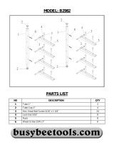
Hardware Parts List for Models STS2611ALP/NG & STS3211ALP/NG
4
Hardware Diagram for Models STS2611ALP/NG & STS3211ALP/NG
Phillips Head Screw 3/16"x3/8"
Qty. 14 (for STS2611ALP & STS3211ALP)
Qty. 8 (for STS2611ANG & STS3211ANG)
Part # S112G0306E
Phillips Head Screw 1/4"x3/8"
Qty. 8
(for STS2611ALP/NG & STS3211ALP/
NG)
Part # S112G0406E
Flange Nut 3/16"
Qty. 22 (for STS2611ALP &
STS3211ALP)
Qty. 16 (for STS2611ANG &
STS3211ANG)
Part # S313G03051
Side Shelf Lock
Qty. 4
(for STS2611ALP/NG & STS3211ALP/NG)
Part # P055010174
Hose Holder
Qty. 2 (for STS2611ALP & STS3211ALP)
Qty. 1 (for STS2611ANG & STS3211ANG)
Part # P05536001A
Pan Head Screw 1/4"x1-3/16"
Qty. 4
(for STS2611ALP/NG & STS3211ALP/NG)
Part # S182G04191
For Installing the Bowl to the Cart
(Already installed in the Bowl Brackets)
Wing Bolt 1/4"x1/2"
Qty. 1
(for STS2611ALP & STS3211ALP)
Part # S233G04084
For Installing the Tank Holder Assembly
(Already installed in Tank Holder Assembly)
PART #
PART DESCRIPTION
PURPOSE OF PART
P06006027A
Hardware Pack
For use in assembly of STS2611ALP/NG & STS3211ALP/NG
S112G0306E
Phillips Head Screw 3/16"x3/8"
S313G03051
Flange Nut 3/16"
S112G0306E
Phillips Head Screw 3/16"x3/8"
S313G03051
Flange Nut 3/16"
S112G0406E
Phillips Head Screw 1/4"x3/8"
P055010174
Side Shelf Lock
S112G0308E
Phillips Head Screw 3/16"×1/2"
S313G03051
Flange Nut 3/16"
S112G0306E
Phillips Head Screw 3/16"x3/8"
4 (LP)
2 (NG)
S313G03051
Flange Nut 3/16"
4 (LP)
2 (NG)
P05536001A
Hose Holder
2 (LP)
1 (NG)
Already Installed in the Bowl Brackets
S182G04191Pan Head Screw 1/4"x1-3/16" Install the Bowl to the Cart (for STS2611ALP/NG & STS3211ALP/NG)
Already installed on the Tank Holder
S233G04084Wing Bolt 1/4"x1/2" Install Tank Holder Assembly (for STS2611ALP & STS3211ALP)
4
1
8
4
2
8
Install the Hose Holders (for STS2611ALP/NG & STS3211ALP/NG)
QTY
Install the Tank Holder Brackets (for STS2611ALP & STS3211ALP)
Install the Side Shelves (for STS2611ALP/NG & STS3211ALP/NG)
Install the Bowl Brackets to the Cart (for STS2611ALP/NG &
STS3211ALP/NG)
1
4
4
6
6
Phillips Head Screw 3/16"x1/2"
Qty. 2
(for STS2611ALP/NG & STS3211ALP/NG)
Part # S112G0308E

5
Hardware Parts List for Models STS2611ALP & STS2611BLP
Flange Nut 1/4"
Qty. 8 (for STS2611BLP)
Part # S313G04081
Phillips Head Screw 1/4"x3/8"
Qty. 12 (for STS2611BLP)
Part # S112G0406E
Hardware Diagram for Models STS2611ALP & STS2611BLP
Phillips Head Screw 3/16"x3/8"
Qty. 4 (for STS2611BLP)
Part # S112G03066
Wing Bolt 1/4"x1/2"
Qty. 1 (for STS2611BLP)
Part # S233G04084
For Installing the Tank Holder Assembly
(Already installed in Tank Holder Assembly)
Pan Head Screw 1/4"x3/8"
Qty. 2 (for STS2611BLP)
Part # S182G0406E
Phillips Head Screw 3/16"x3/8"
Qty. 2 (for STS2611BLP)
Part # S112G0306A
Flange Nut 3/16"
Qty. 2 (for STS2611BLP)
Part # S313G0305A
*One Battery/AA included in the Hardware Pack
(for STS2611ALP & STS2611BLP)
Flange Nut 3/16"
Qty. 4 (for STS2611BLP)
Part # S313G03066
PART #
PART DESCRIPTION
QTY
PURPOSE OF PART
P06006023A
Hardware Pack
1
For use in assembly STS2611ALP & STS2611BLP
S112G0406E
Phillips Head Screw 1/4"x3/8"
12
S182G0406E
Pan Head Screw 1/4"x3/8"
2
S313G04081
Flange Nut 1/4"
8
S112G0306A
Phillips Head Screw 3/16"x3/8"
2
S313G0305A
Flange Nut 3/16"
2
S112G03066
Phillips Head Screw 3/16"x3/8"
4
S313G03066 Flange Nut 3/16" 4
S233G04084 Wing Bolt 1/4"x1/2" 1 Install Tank Holder Assembly (for STS2611BLP)
Install the Tank Holder Brackets (for STS2611BLP)
Install Bowl Side Trim Brackets (for STS2611BLP)
Install the LP Regulator Bracket (for STS2611BLP)
Already installed on the Tank Holder

Hardware Parts List for Models STS3211ALP & STS3211BLP
Phillips Head Screw 1/4"x3/8"
Qty. 12 (for STS3211BLP)
Part # S112G0406E
Hardware Diagram for Models STS3211ALP & STS3211BLP
6
*One Battery/AA included in the Hardware Pack
(for STS3211ALP & STS3211BLP)
Pan Head Screw 1/4"x3/8"
Qty. 2 (for STS3211BLP)
Part # S182G0406E
Flange Nut 1/4"
Qty. 8 (for STS3211BLP)
Part # S313G04081
Wing Bolt 1/4"x1/2"
Qty. 1 (for STS3211BLP)
Part # S233G04084
For Installing the Tank Holder Assembly
(Already installed in Tank Holder Assembly)
Flange Nut 3/16"
Qty. 2 (for STS3211BLP)
Part # S313G0305A
Phillips Head Screw 3/16"x1/2"
Qty. 4
(for STS3211ALP & STS3211BLP)
Part # S112G0308E
Hex Nut 3/16"
Qty. 4
(for STS3211ALP & STS3211BLP)
Part # S362G0306E
Phillips Head Screw 3/16"x3/8"
Qty. 2 (for STS3211BLP)
Part # S112G0306A
Phillips Head Screw 3/16"x3/8"
Qty. 4 (for STS3211BLP)
Part # S112G03066
Flange Nut 3/16"
Qty. 4 (for STS3211BLP)
Part # S313G03066
PART #
PART DESCRIPTION
QTY
PURPOSE OF PART
P06006025A
Hardware Pack
1
For use in assembly for STS3211ALP & STS3211BLP
S112G0406E
Phillips Head Screw 1/4"x3/8"
12
S182G0406E
Pan Head Screw 1/4"x3/8"
2
S313G04081
Flange Nut 1/4"
8
S112G0308E
Phillips Head Screw 3/16"x1/2"
4
S362G0306E
Hex Nut 3/16"
4
S112G0306A
Phillips Head Screw 3/16"x3/8"
2
S313G0305A
Flange Nut 3/16"
2
S112G03066
Phillips Head Screw 3/16"x3/8"
4
S313G03066
Flange Nut 3/16"
4
S233G04084 Wing Bolt 1/4"x1/2" 1 Install Tank Holder Assembly (for STS3211BLP)
Already installed on the Tank Holder
Install the Tank Holder Brackets (for STS3211BLP)
Install the Transformer (for STS3211ALP & STS3211BLP)
Install Bowl Side Trim Brackets (for STS3211BLP)
Install the LP Regulator Bracket (for STS3211BLP)

7
Hardware Diagram for Models STS2611ANG & STS2611BNG
Hardware Pack for Models STS2611ANG & STS2611BNG
Phillips Head Screw 3/16"x1/2"
Qty. 3 (for STS2611BNG)
Part # S112G0308E
Flange Nut 1/4"
Qty. 8 (for STS2611BNG)
Part # S313G04081
Phillips Head Screw 1/4"x3/8"
Qty. 12 (for STS2611BNG)
Part # S112G0406E
Phillips Head Screw 3/16"x1/4"
Qty. 2
(for STS2611ANG & STS2611BNG)
Part # S112G0304E
PART # PART DESCRIPTION QTY PURPOSE OF PART
P06006026A Hardware Pack 1 For use in assembly for STS3211ANG & STS3211BNG
S112G0406E Phillips Head Screw 1/4"x3/8" 12
S182G0406E Pan Head Screw 1/4"x3/8" 2
S313G04081 Flange Nut 1/4" 8
S112G0308E Phillips Head Screw 3/16"x1/2" 4
S362G0306E Hex Nut 3/16" 4
S112G0304E Phillips Head Screw 3/16"x1/4" 2 Install the NG Regulator (for STS3211ANG & STS3211BNG)
S112G0308E Phillips Head Screw 3/16"x1/2" 3
S313G03051
Flange Nut 3/16"
3
Install NG Regulator Bracket (for STS3211BNG)
Install the Transformer (for STS3211ANG &STS3211BNG)
Install Bowl Side Trim Brackets (for STS3211BNG)
*One Battery/AA included in the Hardware Pack
(for STS3211ANG & STS3211BNG)
*One Battery/AA included in the Hardware Pack
(for STS2611ANG & STS2611BNG)
Phillips Head Screw 3/16"x1/4"
Qty. 2
(for STS3211ANG & STS3211BNG)
Part # S112G0304E
Phillips Head Screw 3/16"x1/2"
Qty. 4 (for STS3211ANG)
Qty. 7 (for STS3211BNG)
Part # S112G0308E
Pan Head Screw 1/4"x3/8"
Qty. 2 (for STS2611BNG)
Part # S182G0406E
Flange Nut 3/16"
Qty. 3 (for STS2611BNG)
Part # S313G03051
Hardware Parts List for Models STS3211ANG & STS3211BNG
Hardware Diagram for Models STS3211ANG & STS3211BNG
Phillips Head Screw 1/4"x3/8"
Qty. 12 (for STS3211BNG)
Part # S112G0406E
Pan Head Screw 1/4"x3/8"
Qty. 2 (for STS3211BNG)
Part # S182G0406E
Flange Nut 1/4"
Qty. 8 (for STS3211BNG)
Part # S313G04081
Flange Nut 3/16"
Qty. 3 (for STS3211BNG)
Part # S313G03051
Hex Nut 3/16"
Qty. 4
(for STS3211ANG & STS3211BNG)
Part # S362G0306E
PART # PART DESCRIPTION QTY PURPOSE OF PART
P06006024A Hardware Pack 1 For use in assembly for Models STS2611ANG & STS2611BNG
S112G0406E Phillips Head Screw 1/4"x3/8" 12
S182G0406E Pan Head Screw 1/4"x3/8" 2
S313G04081 Flange Nut 1/4" 8
S112G0304E Phillips Head Screw 3/16"x1/4" 2 Install the NG Regulator (for STS2611ANG & STS2611BNG)
S112G0308E Phillips Head Screw 3/16"x1/2" 3
S313G03051
Flange Nut 3/16"
3
Install NG Regulator Bracket (for STS2611BNG)
Install Bowl Side Trim Brackets (for STS2611BNG)

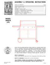
Parts Diagram for Models STS2611ALP/NG
8
78
61
31
10B
25
26
20
19
18
23
37B
21
56A
22
70
69
68
67
66
65
54
57
55
56B
58
52
50
48
62
59
46
53
64
45B
51
47
45A
49
62
64
60
44
73
17
75
72
74
13
15
16
14
77
76
40
39
38
37A
36
71
4
5
3
6
2
1
34
41
29
35
30
27
28
24
22
43
42
10A
8
7
9
11
12
32
33
32
76A
33
63

Parts List for Model STS2611ALP/NG
9
KEY DESCRIPTION PART# QTY
1 Lid Assembly P001462764 1
2 Temperature Gauge P00601071A 1
3 Lid Handle Bracket, Left P03303124A 1
4 Lid Handle Bracket, Right P03303125A 1
5 Lid Handle P00218001R 1
6 Protective Pad P05518002I 4
7 Cooking Rack/Secondary P01505009K 1
8 Cooking Grid, 13" P01604013B 2
9 Burner/Main P02003003B 4
10A
Flame Tamer/Ceramic, Front
P01804012A 4
10B
Flame Tamer/Ceramic, Rear
P01804013A 4
11
Flame Tamer Rack
P01720038B 1
12 Burner Bracket Assembly P022092154 1
13 Cart Wind Shield, Rear P069060794 1
14 Rotisserie Burner Wind Shield P069060804 1
15 Connecting Hose for Rotisserie Burner P03717056A 1
Rotisserie Burner Orifice (LPG) P06534005A 1
Rotisserie Burner Orifice (NG) P06534009A 1
17 Rotisserie Burner Assembly P02007072A 1
18 Bowl Assembly P0071374D4 1
19 Thermocouple Bracket/Rotisserie Burner P033280494 1
20 Lid Hinge P05501020A 2
21 Door Handle P00218003R 2
22 Bowl Grease Shield P069020184 2
23 Lighting Tube P05507012A 1
24 Bowl Heat Shield P069040514 1
25 Electric Ignitor Protector P03328048Q 1
26 Electric Wire Set P02627009A 1
27
Gas Collector Box with Electrode
P026090154 4
28
Electrode Wire Set
P02615160A 1
29
Extension Fitting for Manifold
P03902029A 1
Gas Valve/Manifold Assembly (LPG) Y0060675 1
Gas Valve/Manifold Assembly (NG) Y0060676 1
31 Door Guide Plate P055100244 1
32 Hose, 12FT. (NG) 3/8"ID P03703001A 1
33 Door Handle Bracket P00217002I 4
34 Control Panel Heat Shield P06919003B 1
35
Control Panel, Upper
P02913441X 1
36
Control Panel, Lower
P02913456X 1
37A Control Knob/Main Burner P03419583L 4
37B Control Knob/Rotisserie/Infrared Burner P03419593L 1
38 Control Knob Seat P03413033J 5
39 Electric Ignitor, 5-Port P02502298C 1
40 Grease Tray Assembly P027064034 1
41 Extension Tube P03720003A 1
42 Regulator with Hose (LPG) P03601040A 1
43 Lighting Stick P05313025B 1
44 Cart Panel/Rear P077010824 1
45A Bowl Bracket, Left P01301014K 1
45B Bowl Bracket, Right P01302014K 1
46 Cart Bottom Shelf P010060524 1
47 Cart Side Panel, Left P076170484 1
16
30

Parts List for Models STS2611ALP/NG
10
KEY DESCRIPTION PART# QTY
48 Cart Side Panel, Right P076180494 1
49 Door Hinge Bracket, Upper Left P033020144 1
50 Door Hinge Bracket, Upper Right P033020154 1
51 Door Hinge, Left/Lower P033020374 1
52 Door Hinge, Right/Lower P033020384 1
53 Cart Bracket, Front P033050744 1
54 Tank Holder Assembly (LPG) P053580034 1
55 Slide Set P05516013C 2
56A Slide Set Support, Left P033280664 1
56B Slide Set Support, Right P033280674 1
57 Tank Tray P040110024 1
58 Caster Seat, Right Front/Left Rear P03305078F 2
59 Caster, 2.5" with Brake P05110006D 4
60 Door Assembly, Left P043020514 1
61 Door Assembly, Right P043030514 1
62 Side Shelf Lock P055010174 4
63 Side Shelf Bracket, Left P03311046C 1
64 Side Shelf P011050424 2
65 Side Shelf Bracket, Right P03311047C 1
66 Door Magnet P05523004K 4
67 Weight P05344003Q 1
68 Caster Seat, Left Front/Right Rear P03305079F 2
69 Tank Holder Bracket, Left (LPG) P033040554 1
70 Tank Holder Bracket, Right (LPG) P033040564 1
71 Lid Handle Heat Insulating Spacer P06802007A 2
72 Rotisserie Burner Wind Shield P069060824 1
73 Thermocouple for Rotisserie Burner P05305062A 1
74 Rotisserie Burner Frame P020110654 1
75 Rotisserie Burner Electrode P02614025A 1
76 Regulator with Hose Assembly (NG) P03614007A 1
76A Bracket for NG Regulator (NG) P033040544 1
Hose Holder/Grill (LPG) P055360014 2
Hose Holder/Grill (NG) P055360014 1
78 Gas Valve/Manifold Extension P05005392G 1
Rotisserie Assembly Y0250171 1
Hardware Pack (Cart) P06006027A 1
Hardware Pack (LPG) P06006023A 1
Hardware Pack (NG) P06006024A 1
Operator's Manual P80151035A 1
77

11
Parts Diagram for Models STS3211ALP/NG
14
12
9
7
71
1
2
11A
10
54
65
66
47
48
13
6
16
19
21
26
27
32
31
15
20
35
39
33
46
38
70
3
5
4
68
85
70
68
8
40
41A
42
43
4445
81
82
26
51
49A
53
55
49B
50
64
63
57
56
58
52
62B
61
60
67
59
72
73
74
75
76
77
78
79
80
83
84
62A
37
23
30
30
30
41B
29
87
88
89
28
36
86
11B
25
22
90
34
18
24
17
81A
69

Parts List for Models STS3211ALP/NG
12
KEY DESCRIPTION PART# QTY
1 Lid Assembly P001473364 1
2 Temperature Gauge P00601071A 1
3 Lid Handle Bracket, Left P03303124A 1
4 Lid Handle Bracket, Right P03303125A 1
5 Lid Handle P00218002R 1
6 Protective Pad P05518002I 4
7 Cooking Rack/Secondary P01516004B 1
8 Cooking Grid, 13" P01604013B 2
9 Burner/Main P02003003B 3
10 Infrared Burner P02005026B 1
11A Flame Tamer/Ceramic, Front P01804012A 3
11B Flame Tamer/Ceramic, Rear P01804013A 3
12 Flame Tamer Rack P01722002B 1
13 Burner Heat Shield P069060454 1
14 Burner Bracket Assembly P02203145A 1
15 Cart Wind Shield, Rear P069060814 1
16 Rotisserie Burner Wind Shield P069060464 1
17 Light Cover Set P053830034 2
18 Light, 12V, 10W P05383002B 2
Rotisserie Burner Orifice (LPG) P06534005A 1
Rotisserie Burner Orifice (NG) P06534009A 1
20 Rotisserie Burner Assembly P02007072A 1
21 Rotisserie Burner Extension Tube P03717050B 1
22 Bowl Assembly P0071375D4 1
23 Door Handle P00218003R 3
24 Light Wire Set P05352005B 1
25 Hose, 12FT. (NG) 3/8"ID P03703001A 1
26 Bowl Grease Shield P069020184 2
27 Bowl Heat Shield P069030564 1
28 Transformer P05374003B 1
29 Lighting Tube P05507012A 1
30 Door Handle Bracket P00217002I 6
31 Gas Collector Box with Electrode P026090154 3
32 Electrode Wire Set P02615161A 1
33 Extension Fitting for Manifold P03902029A 1
34 Gas Valve/Manifold Extension P05005392G 1
Gas Valve/Manifold Assembly (LPG) Y0060673 1
Gas Valve/Manifold Assembly (NG) Y0060674 1
36 Lid Hinge P05501020A 2
37 Thermocouple Bracket/Rotisserie Burner P033280494 1
38 Control Panel Heat Shield P06919002B 1
39 Control Panel, Upper P02915271X 1
40 Control Panel, Lower P02915286X 1
41A Control Knob/Main Burner P03419583L 3
41B Control Knob/Rotisserie/Infrared Burner P03419593L 2
42 Control Knob Seat P03413033J 5
43 Switch for Light P05360002B 1
44 Electric Ignitor, 5-Port P02502298C 1
45 Grease Tray Assembly P027071034 1
46 Extension Tube P03720003A 1
47 Regulator with Hose (LPG) P03601040A 1
48 Lighting Stick P05313022B 1
49A Bowl Bracket, Left P01301014K 1
49B Bowl Bracket, Right P01302014K 1
50 Cart Side Panel, Right P076180494 1
51 Cart Panel/Rear P077021144 1
19
35

13
Parts List for Models STS3211ALP/NG
Important: Use only Grand Hall replacement parts. The use of any part that is not a Grand Hall replacement part can be
dangerous and will also void your product warranty. Keep this Operator's Manual for convenient referral and for part
replacement.
For the repair or replacement parts you need:
Call 1-877-934-7455 M-F 8AM-4:30 PM CST
To obtain the correct replacement parts for your gas grill, please refer to the part numbers in this parts list. The
following information is required to ensure you receive the correct parts:
1. Model and Serial Number (see CSA label on grill)
2. Part Number
3. Part Description
4. Quantity of parts needed
KEY DESCRIPTION PART# QTY
52 Cart Bottom Shelf P010020714 1
53 Door Hinge Bracket, Upper Left P033020144 1
54 Door Hinge, Left/Lower P033020374 1
55 Cart Side Panel, Left P076170484 1
56 Side Shelf Bracket, Rear P033110454 1
57 Cart Bracket, Front P033050804 1
58 Side Shelf Bracket, Front P033110424 1
59 Tank Holder Assembly (LPG) P053580034 1
60 Tank Tray P040110024 1
61 Slide Set P05516013C 2
62A Slide Set Support, Left P033280664 1
62B Slide Set Support, Right P033280674 1
63 Caster Seat, Right Front/Left Rear P03305078F 2
64 Caster, 2.5" with Brake P05110006D 4
65 Door Assembly P043010464 1
66 Drawer Assembly P01913002I 2
67 Slide Set for Drawer P05516141C 4
68 Side Shelf Lock P055010174 4
69 Side Shelf Bracket, Left P03311046C 1
70 Side Shelf P011050424 2
71 Cooking Grid, 6.5" P01604031B 1
72 Caster Seat, Left Front/Right Rear P03305079F 2
73 Door Magnet P05523004K 2
74 Weight P05344009Q 1
75 Lid Handle Heat Insulating Spacer P06802007A 2
76 Rotisserie Burner Wind Shield P069060824 1
77 Rotisserie Burner Electrode P02614025A 1
78 Thermocouple for Rotisserie Burner P05305051A 1
79 Rotisserie Burner Frame P020110664 1
80 Infrared Burner Electrode/Thermocouple Assembly P02614056A 1
81 Regulator with Hose Assembly (NG) P03614007A 1
81A Bracket for NG Regulator (NG) P033040544 1
Hose Holder/Grill (LPG) P055360014 2
Hose Holder/Grill (NG) P055360014 1
83 Tank Holder Bracket, Left (LPG) P033040554 1
84 Tank Holder Bracket, Right (LPG) P033040564 1
85 Side Shelf Bracket, Right P03311047C 1
86 Door Guide Plate P055100244 1
87 Electric Ignitor Protector P03328048Q 1
88 Electric Wire Set P02627010A 1
89 Thermocouple for Infrared Burner P05305050A 1
90 Thermocouple Bracket P03343008C 1
Rotisserie Assembly Y0250172 1
Hardware Pack (Cart) P06006027A 1
Hardware Pack (LPG) P06006025A 1
Hardware Pack (NG) P06006026A 1
Operator's Manual P80151035A 1
82

Parts Diagram for Models STS2611BLP/NG
14
12
11
9
7
8
10A
42
43
22
24
28
27
30
35
29
41
34
1
2
6
3
5
4
44
36
37A
38
39
40
51
53
14
16
15
13
49
46
48
17
47
22
33
37B
23
18
19
20
26
50
10B
31
55
21
25
54
52
51A
45
32

Parts List for Models STS2611BLP/NG
15
KEY DESCRIPTION PART# QTY
1 Lid Assembly P001462764 1
2 Temperature Gauge P00601071A 1
3 Lid Handle Bracket, Left P03303124A 1
4 Lid Handle Bracket, Right P03303125A 1
5 Lid Handle P00218001R 1
6 Protective Pad P05518002I 4
7 Cooking Rack/Secondary P01505009K 1
8 Cooking Grid, 13" P01604013B 2
9 Burner/Main P02003003B 4
10A
Flame Tamer/Ceramic, Front
P01804012A 4
10B
Flame Tamer/Ceramic, Rear
P01804013A 4
11
Flame Tamer Rack
P01720038B 1
12 Burner Bracket Assembly P022092154 1
13 Cart Wind Shield, Rear P069060794 1
14 Rotisserie Burner Wind Shield P069060804 1
15 Connecting Hose for Rotisserie Burner P03717056A 1
Rotisserie Burner Orifice (LPG) P06534005A 1
Rotisserie Burner Orifice (NG) P06534009A 1
17 Rotisserie Burner Assembly P02007072A 1
18 Bowl Assembly P0071374D4 1
19 Thermocouple Bracket/Rotisserie Burner P033280494 1
20 Lid Hinge P05501020A 2
21 Bowl Trim Bracket, Right
P079010374
1
22 Bowl Grease Shield P069020184 2
23 Lighting Tube P05507012A 1
24 Bowl Heat Shield P069040514 1
25 Bowl Trim Bracket, Left
P079010364
1
26 Electric Wire Set P02627009A 1
27
Gas Collector Box with Electrode
P026090154 4
28
Electrode Wire Set
P02615160A 1
29
Extension Fitting for Manifold
P03902029A 1
Gas Valve/Manifold Assembly (LPG) Y0060675 1
Gas Valve/Manifold Assembly (NG) Y0060676 1
31 Gas Valve/Manifold Extension P05005392G 2
32 Hose, 12FT. (NG) 3/8"ID P03703001A 1
33 Bowl Bracket, Right P01302014K 1
34 Control Panel Heat Shield P06919003B 1
35
Control Panel, Upper
P02913441X 1
36
Control Panel, Lower
P02913456X 1
37A Control Knob/Main Burner P03419583L 4
37B Control Knob/Rotisserie/Infrared Burner P03419593L 1
38 Control Knob Seat P03413033J 5
39 Electric Ignitor, 5-Port P02502298C 1
40 Grease Tray Assembly P027064034 1
41 Extension Tube P03720003A 1
42 Regulator with Hose (LPG) P03601043A 1
43 Lighting Stick P05313025B 1
44 Lid Handle Heat Insulating Spacer P06802007A 2
45 Tank Holder Assembly (LPG) P05358003H 1
16
30

Parts List for Models STS2611BLP/NG
16
KEY DESCRIPTION PART# QTY
46 Rotisserie Burner Wind Shield P069060824 1
47 Thermocouple for Rotisserie Burner P05305062A 1
48 Rotisserie Burner Electrode P02614025A 1
49 Rotisserie Burner Frame P020110654 1
50 Electric Ignitor Protector P03328048Q 1
51 Regulator with Hose Assembly (NG) P03614007A 1
51A Bracket for NG Regulator (NG) P033040544 1
52 Tank Holder Bracket, Left (LPG) P03304055F 1
53 Tank Holder Bracket, Right (LPG) P03304056F 1
54 Bowl Trim Bracket, Rear P079010294 1
55 Bowl Bracket, Left P01301014K 1
Rotisserie Assembly Y0250171 1
Hardware Pack (LPG) P06006023A 1
Hardware Pack (NG ) P06006024A 1
Operator's Manual P80151035A 1

17
Parts Diagram for Models STS3211BLP/NG
62
61A
14
12
9
7
36
1
2
11A
10
47
48
13
6
16
17
19
21
26
27
32
31
15
59
20
35
39
33
46
38
3
5
4
8
40
41A
42
43
44
45
26
30
50
52
51
54
57
37
41B
29
18
58
49
55
53
60
23
61
11B
22
56
34
65
66
24
64
63
25
28

Parts List for Models STS3211BLP/NG
18
KEY DESCRIPTION PART# QTY
1 Lid Assembly P001473364 1
2 Temperature Gauge P00601071A 1
3 Lid Handle Bracket, Left P03303124A 1
4 Lid Handle Bracket, Right P03303125A 1
5 Lid Handle P00218002R 1
6 Protective Pad P05518002I 4
7 Cooking Rack/Secondary P01516004B 1
8 Cooking Grid, 13" P01604013B 2
9 Burner/Main P02003003B 3
10 Infrared Burner P02005026B 1
11A
Flame Tamer/Ceramic, Front
P01804012A 3
11B
Flame Tamer/Ceramic, Rear
P01804013A 3
12
Flame Tamer Rack
P01722002B 1
13 Burner Heat Shield P069060454 1
14 Burner Bracket Assembly P02203145A 1
15 Cart Wind Shield, Rear P069060814 1
16 Rotisserie Burner Wind Shield P069060464 1
17 Light Cover Set P053830034 2
18 Light, 12V, 10W P05383002B 2
Rotisserie Burner Orifice (LPG) P06534005A 1
Rotisserie Burner Orifice (NG) P06534009A 1
20 Rotisserie Burner Assembly P02007072A 1
21 Rotisserie Burner Extension Tube P03717050B 1
22 Bowl Assembly P0071375D4 1
23 Lid Hinge P05501020A 2
24 Bowl Trim Bracket, Left
P079010364
1
25 Hose, 12FT. (NG) 3/8"ID P03703001A 1
26 Bowl Grease Shield P069020184 2
27 Bowl Heat Shield P069030564 1
28 Tank Holder Assembly (LPG) P05358003H 1
29 Lighting Tube P05507012A 1
30 Lid Handle Heat Insulating Spacer P06802007A 2
31
Gas Collector Box with Electrode
P026090154 3
32
Electrode Wire Set
P02615161A 1
33
Extension Fitting for Manifold
P03902029A 1
34 Gas Valve/Manifold Extension P05005392G 1
Gas Valve/Manifold Assembly (LPG) Y0060673 1
Gas Valve/Manifold Assembly (NG) Y0060674 1
36 Cooking Grid, 6.5" P01604031B 1
37 Bowl Trim Bracket, Rear
P079010284
1
38 Control Panel Heat Shield P06919002B 1
39
Control Panel, Upper
P02915271X 1
40
Control Panel, Lower
P02915286X 1
41A Control Knob/Main Burner P03419583L 3
41B Control Knob/Rotisserie/Infrared Burner P03419593L 2
42 Control Knob Seat P03413033J 5
43 Switch for Light P05360002B 1
44 Electric Ignitor, 5-port P02502298C 1
45 Grease Tray Assembly P027071034 1
46 Extension Tube P03720003A 1
19
35

19
Parts List for Models STS3211BLP/NG
Important: Use only Grand Hall replacement parts. The use of any part that is not a Grand Hall replacement part can be
dangerous and will also void your product warranty. Keep this Operator's Manual for convenient referral and for part
replacement.
For the repair or replacement parts you need:
Call 1-877-934-7455 M-F 8AM-4:30 PM CST
To obtain the correct replacement parts for your gas grill, please refer to the part numbers in this parts list. The
following information is required to ensure you receive the correct parts:
1. Model and Serial Number (see CSA label on grill)
2. Part Number
3. Part Description
4. Quantity of parts needed
KEY DESCRIPTION PART# QTY
47 Regulator with Hose (LPG) P03601043A 1
48 Lighting Stick P05313022B 1
49 Electric Wire Set P02627010A 1
50 Rotisserie Burner Wind Shield P069060824 1
51 Thermocouple for Rotisserie Burner P05305051A 1
52 Rotisserie Burner Electrode P02614025A 1
53 Thermocouple Bracket/Rotisserie Burner P033280494 1
54 Rotisserie Burner Frame P020110664 1
55 Thermocouple for Infrared Burner P05305050A 1
56 Thermocouple Bracket P03343008C 1
57 Infrared Burner Electrode/Thermocouple Assembly P02614056A 1
58 Electric Ignitor Protector P03328048Q 1
59 Light Wire Set P05352005B 1
60 Transformer P05374003B 1
61 Regulator with Hose Assembly (NG) P03614007A 1
61A Bracket for NG Regulator (NG) P033040544 1
62 Tank Holder Bracket, Left (LPG) P03304055F 1
63 Tank Holder Bracket, Right (LPG) P03304056F 1
64 Bowl Trim Bracket, Right P079010374 1
65 Bowl Bracket, Left P01301014K 1
66 Bowl Bracket, Right P01302014K 1
Rotisserie Assembly Y0250172 1
Hardware Pack (LPG) P06006025A 1
Hardware Pack (NG ) P06006026A 1
Operator's Manual P80151035A 1

Rotisserie Assembly Parts Diagram
Rotisserie Assembly Parts List
Hardware for Rotisserie
Rot. Screw#10-24x3/4"
UNC
Qty. 2
Part # S112G10124
Rot. Thumbscrew
1/4"x1/2"
Qty. 3
Part # S196G04084
Rot. Washer 3/16"
Qty. 2
Part # S411G03084
Rot. Nut.#10-24
Qty. 2
Part # S362G10124
KEY
PART#
DESCRIPTION
QTY
1.
2.
3.
4.
5.
6.
7.
8.
9.
Grill Information Center: If you have questions about assembly or grill operation, or if there are damaged
or missing parts when you unpack this unit from the shipping box, call us 8:00 am - 8 pm CST, Monday
through Friday at: 1-888-317-7642
20
Grill Information Center: If you have questions about assembly or grill operation, or if there are damaged or missing
parts when you unpack this unit from the shipping box, Call 1-877-934-7455 M-F 8AM-4:30 PM CST
6
7
9
8
5
4
4
2
2
3
2
1
Rot. Collar
Rot. Thumbscrew 1/4"x1/2"
Rot. Spit (for STS2611ALP/NG Models)
Rot. Spit (for STS3211ALP/NG Models)
Rot. Holding Fork
Rot. Motor Bracket
Rot. Motor/AC
Rot. Screw#10-24x3/4"UNC
Rot. Washer 3/16"
Rot. Nut #10-24
1.
2.
3.
4.
5.
6.
7.
8.
9.
1
3
1
1
2
1
1
2
2
2
P05508177F
S196G04084
P05508202F
P05508203F
P05508023F
P05508174F
P07101039B
S112G10124
S411G03084
S362G10124
1.
2.
3.
4.
5.
6.
7.
8.
9.
/