Bobrick B-8876 Installation guide

Category
Sanitary ware
Type
Installation guide

This manual is also suitable for

Form No. 8878-69 (Revised 3/10/20) © 2020 Bobrick Washroom Equipment, Inc. Printed in U.S.A.
1
INSTALLATION, OPERATION
INSTRUCTIONS AND PARTS MANUAL
SENSOR-OPERATED LAVATORY FAUCETS
FOR BATTERY FOR PLUG-IN INSTALLATIONS
B-8870 Polished Brass
B-8872 Matte Black
B-8875 Brushed Nickel
B-8876 Polished Nickel
B-8878 Polished Chrome
Patented: PAT. www.Bobrick.com
NOTICE: READ ENTIRE MANUAL PRIOR TO INSTALLING PRODUCT
.
NOTE: The information in this manual is subject to change at any time without notice. Installations may be performed at
dierent times of construction by dierent individuals. For this reason, these instructions should be left on-site with the
facility or maintenance manager.
Form No. 8878-69 (Revised 3/10/20) © 2020 Bobrick Washroom Equipment, Inc. Printed in U.S.A.
2
Spout
Assembly
Base
Gasket
Aerator
and Key
Electronics Box
with Solenoid
Batteries
Filter
Shank
Mounting Kit
Phillips Head
Screwdriver
Allen Wrench (3/32")
(Supplied)
Allen Wrench (M3)
(Supplied)
Non-toothed
Wrench
Voltage: Sensor Range:
Sensor Range:
Operating Water Pressure:
Operational Water Temperature:
Flow Control:
6 VDC Series [4 “AA” (Alkaline or Lithium) and/or external power option]
Self-calibrated, dependent upon sink depth and nish.
10-125 psi
33°F to 140°F (1°C to 60°C)
0.5 GPM / 1.9 LPM Vandal-Resistant Non-Aerated
Overview
Designer Series faucet: the items listed below should already be installed on site.
• Lavatory/sink
• Drain Line
• Hot and cold water supply line or pre-tempered water supply line.
Installer/Servicer should not use pipe dope or teon/thread sealant anywhere on this product, most notably threads
and connection points.
• Care shall be taken when installing this product to prevent marring of any exposed or decorative surfaces.
Be sure the sink/lavatory/basin is clear from any objects upon making the sensor to electronics connection initiating
the self calibration feature. The sink must be clear of any and all objects in order to calibrate appropriately (calibration
time approx 30-60 sec).
Designer Series Faucet features multiple spout design in a standard polished chrome nish with one piece heavy duty
cast brass spout, advanced electronic components and feature sets. Sophisticated automatic user detection and self-
calibration ensures the user does not need to touch the faucet and helps deliver optimum water savings.
Specications
Overview
Prior to Installation
• Installer is responsible for ensuring the product is installed and conforms to all plumbing codes and ordinances.
• Do not convert or modify this product yourself. All warranties will be voided.
Water supply lines must be sized according to building designer in order to provide adequate water supply for each xture.
• Flush all water lines prior to making connections.
Required Tools:
Package Contents
Form No. 8878-69 (Revised 3/10/20) © 2020 Bobrick Washroom Equipment, Inc. Printed in U.S.A.
3
Installation
NOTE: Before installation, turn o water supplies to existing faucet and remove faucet if replacing an existing device. Clean the
faucet basin and clear away debris. Flush all supply lines before connecting the faucet. Failure to do so may result in debris clogging
the inlets and/or internal control and mixing valve
Spout Installation - Step 1
1.1.
Carefully screw aerator into spout using included tool.
Take care to not pinch blue o-ring
1.2.
Install spout to sink using spout base gasket, plastic mounting
washer, star washer and mounting nut (and cover plate for
versions that are included)
.
Electronics Module Installation - Step 2
2.1. Assemble the electronics module.
2.1a. For non-IM assembly, connect lter to bottom of
electronics module.
Sensor cable should not pass through plastic
mounting washer.
1.3. Ensure that slot in plastic washer is facing forward
2.2.
Open battery module using supplied Allen wrench and install
supplied batteries in the electronics module
Form No. 8878-69 (Revised 3/10/20) © 2020 Bobrick Washroom Equipment, Inc. Printed in U.S.A.
4
ACA
INLINE
CONNECTOR
-CWB
-HW6
-MJ
-HW6
18 AWG (MIN)
MAX LENGTH 40
2.2a. Optional ACA version: Connect supplied inline
connector and AC adapter.
Do not engage the sensor for 30 seconds after the
connection is made. The sensor will perform automatic
calibration.
2.6. Connect solenoid cable from electronics module to
sensor cable from spout.
2.3. Tighten electronics module assembly to shank and
connect water line(s).
2.2b. Optional HW6 (Hardwired 6V) version: Connect
supplied inline connector and hardwire adapter.
When securing the CWB wires to the screw
terminals on HW6 unit, the BLACK WITH DASHED
MARKINGS should be connected to the Positive
(+) terminal, and the SOLID BLACK wire should be
connected to the Negative (-) terminal.
2.4. Turn on water supply(ies).
2.5 Ensure that sink is clear of tools/debris and is in
normal operating condition.
MJ unit (sold separately)
Note: Do not connect more than 8 solenoids to a single
transformer.
Form No. 8878-69 (Revised 3/10/20) © 2020 Bobrick Washroom Equipment, Inc. Printed in U.S.A.
5
1 2 3 4 5 6 7 8
ON
OFF
Switch Position: 1 2 3 4 5 6 7 8
Purge (Hours)
Disable:
12:
24:
48:
Off
On
Off
On
Off
Off
On
On
Time (Seconds)
30:
5:
10:
15:
60:
Less Time-out:
Off
On
Off
On
Off
On
Off
Off
On
On
Off
Off
Off
Off
Off
Off
On
On
Mode Select
Sensing Mode:
Metering Mode:
Off
On
Sensor Sensitivity
High:
Low:
Mode A:
Mode B:
Off
On
Off
On
Off
Off
On
On
Adjustable modes and features
selection:
To adjust features from default conguration, you must
remove the battery tray. Once battery tray is removed you
will see the switches.
Before adjusting switches when electronics box is rst
installed or when replacing dead battery:
1. Temporarily install battery tray with fresh batteries
installed and hold in place for 30 seconds.
2. Remove battery tray and set switches.
3. Re-install battery tray.
Purge Features:
The purge switches can be congured for 4 modes of operation: Disabled (standard conguration), 12 hour, 24 hours,
or 48 hours. Purge water ow duration is 2 minutes. Note: Purge activation occurs every switch selected time (0,12, 24,
or 48 hours) after last activation.
Flow Time:
There are 6 optional time congurations: 30 seconds (standard), 5s, 10s, 15s, 60s, & “Less Time-out”. The “Less Time-
out”
option actually ceases water ow (turns o) after 20 minutes to limit chance of water damage in the event a sink
drain becomes blocked.
Sensing Mode (DEFAULT):
During this mode the valve will shut o after hands are removed. If hands are not removed the time out delay will turn
o the faucet (ex: standard conguration is 30 seconds) (See Sensing & Metering Mode ow chart on following page)
Metering Mode:
When hands are detected by the sensor, water will run for ‘ X’ seconds (standard conguration is 30 seconds) before
turning o. (See Sensing & Metering Mode ow chart on following page)
Sensor Sensitivity: (Default setting: Low):
There are 4 sensitivity options, which can be selected to achieve the optimal detection performance related to the sink
material, shape, & nish. The faucet sensor sensitivity is congured during pack-out but the mode can be changed upon
installation to optimize the performance within the sink. Sensor sensitivity and Modes A & B may be tried for dicult sink
materials and shape.
NOTE: After a conguration switch change has been made, disconnect sensor cable from electronics box, wait 30
seconds, then reconnect sensor cable and wait 30 seconds to allow the sensor to tune-in the sink characteristics.
All switches shown in default mode.
Form No. 8878-69 (Revised 3/10/20) © 2020 Bobrick Washroom Equipment, Inc. Printed in U.S.A.
6
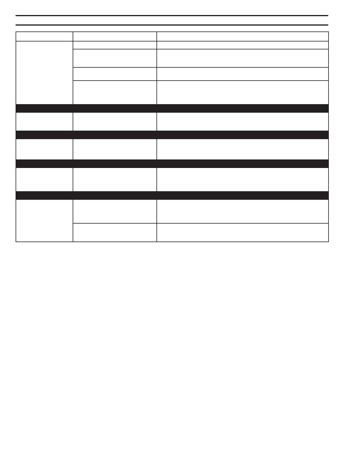
POTENTIAL SITUATIONS POSSIBLE CAUSES SUGGESTED SOLUTION TIPS
Faucet is non-responsive Battery voltage low or no power Change out batteries or verify power provided by HW6 or ACA
Sensor and electronic connector cable has
bent or broken pins
Check to see if pins are missing, bent, or broken. If yes, then the
electronic box needs replaced
Sensor lens could have surface damage,
scratches, or deposit build ups
Inspect the sensor lens underneath the spout tip. May require
cleaning with a damp cloth or sensor replacement
Sensor lens could be obstructed by
environmental factors such as high
reective surfaces or bright lighting
conditions
Disconnect the sensor and electronic box cables and wait for 30
seconds. Reconnect the cables, but allow for another 30 seconds before placing hands or
a target within the sensor range. You should hear a click of the solenoid once calibration is
complete.
Faucet does not activate
after initial installation
Sensor may not have had enough time to
calibrate prior to a user or target trying to
initiate activation
Check to see if pins are missing, bent, or broken. If yes, then the
electronic box needs replaced.
Water does not stop Electronics box cable connector has bent
pins that are shorted
Check/clean sensor lens of any debris or buildup.
If sunlight or IR interference is a factor, refer to page 7 Sensor Sensitivity and adjust faucet
for Mode B operation.
Ghost Activation Sensor lens could be obstructed or
environmental factors such as high
reective surfaces and/or bright sunlight
conditions
Check and ensure the nuts and joints are tight and secure from the supply stop all the way
to the faucet shank.
Sensor faucet is leaking
underneath the sink or
counter
Mounting hardware is not tightened
suciently
(faucet shank, electronic box, supply
hoses, etc)
Check and ensure the nuts and joints are tight and secure from the
supply stop all the w ay to the faucet shank.
Missing the washer located in the solenoid
box nut w here it assembles to the faucet
shank
Make sure the water supply stops are shut of . Check to ensure the washer is installed or
damaged. If not, install washer. If a washer is
installed replace with new.
Troubleshooting Guide
Care and Cleaning Instructions:
Do not use any abrasive or chemical cleaners to clean the faucets.
If abrasives or chemicals are used it can lead to dulling of luster, attacking of chrome plating or decorative
nishes.
ONLY use mildly warm soapy water, and then wipe the device dry with a clean/soft towel or cloth.
Upon cleaning other areas of the restroom be sure the sensor lenses are protected from other cleaning chemicals /
solvents
to prevent potential damages to the sensor and/or electronics.
For further assistance with troubleshooting and spare parts visit http://www.zurn.com
Select "Commercial Brass" option when calling Zurn Customer Service.
Form No. 8878-69 (Revised 3/10/20) © 2020 Bobrick Washroom Equipment, Inc. Printed in U.S.A.
7
SPRING LOCK
SIDE
SET
SCREW
SIDE
Spout Replacement
To replace spout body, you must rst turn water o, then remove spout with sensor cable.
With screws removed, the electronics box can slide o and allow
access to the solenoid for service
Loosening screw will cause sensor assembly to back out of
spout body. It may be necessary to push cable from connector
end to aid in sensor assembly removal. Firmly press into pocket
and tighten screw. Sensor connector may need to be turned
horizontally when rst inserting into the spout.
Align spout so that the ball detent is between the 2 holes. Press
down and turn clockwise. Use hex wrench to back set screw out
to secure spout
Lift spout and pull sensor cable through deck and base
Note location of set screw and spring lock.
Accessing the Solenoid
To service solenoid use Phillips head screw driver to remove the
screws on both sides of the electronics box
Sensor Assembly Replacement
With spout disengaged, sensor assembly can now be removed
by loosening the center screw with supplied M3 Allen wrench.
With assembly removed, you can now install new assembly and
reassemble your spout.
To reinstall faucet, rst drop sensor cable of new spout through
the front of the base. Lower spout onto base inserting base
nipple into spout port.
Use supplied 3/32" hex wrench to loosen set screw. Screw
will retract into the base to eliminate loss. Using the same hex
wrench, depress the ball detent to release spout from base.
Before removing the spout, disconnect the sensor cable below
the deck so that the cable head can be pulled up through the deck.
*Take care to press the locking mechanism in prior to
disconnecting sensor cable. PULLING APART WITHOUT
PRESSING IN THE LOCK MAY DAMAGE THE SENSOR OR
CONTROLLER CABLES.
Form No. 8878-69 (Revised 3/10/20) © 2020 Bobrick Washroom Equipment, Inc. Printed in U.S.A.
8
8
11
21
16
17
7
18
9
BLUE (-)
GREEN/YELLOW
FRAME/SAFETY GROUND
P6000-HW6 WIRING
IN
VAC
(LINE)
BLACK
(NEUTRAL)
WHITE
RED (+)
6
19
20
Bobrick Part Number Zurn Part Number
B-8878 (Polished Chrome) Z6951-XL-BW-E
B-8876 (Polished Nickel) Z6951-XL-PN-BW-E
B-8875 (Brushed Nickel) Z6951-XL-BN-BW-E
B-8870 (Polished Brass) Z6951-XL-PB-BW-E
1 Z6951 Spout Assembly with Sensor P6951-XL-1
2 Spout shank base for Z6950/Z6955-XL P6950-XL-B
3 Z6950 Spout base gasket P6950-XL-42
4 Electronics Box with Solenoid P6950-XL-B-L
5 4" Cast Cover Plate w/Gasket P6950-CP4
6 8" Cast Cover Plate w/Gasket P6950-CP8
7 Z6950 Sensor Assembly P6950-XL-EL
8 Mounting Kit P6900-43
9 Filter Kit P6900-120
10 Filter Screen P6900-MV-7
11. Mixing Valve w/Filter P6900-XL-MV
12. Mixing Tee w/Filters and Back Checks P6900-XL-MT
13. Single Stainless Supply Hose (XL) P6900-SSH
14. Stainless Supply Hoses (XL) P6900-SH
15. Composite Mixing Valve Adaptor P6900-MV-ADAP
16. Shank Connection Gasket P6900-SG
17.
Solenoid Rebuild Kit (Diaphram, plunger and plunger spring)
P6950-SRK
18. Sensor Inline Connector P6950-XL-DC
19. -CWB Pigtail P6900-CWB
20. -HW6 Power Supply P6900-HW6
21. Optional Plug-in Power Converter P6900-ACA
Parts List
Form No. 8878-69 (Revised 3/10/20) © 2020 Bobrick Washroom Equipment, Inc. Printed in U.S.A.
9
All goods sold hereunder are warranted to be free from defects in material and factory workmanship for a period of
three years from the date of purchase. Decorative nishes warranted for one year. We will replace at no costs goods
that prove defective provided we are notied in writing of such defect and the goods are returned to us prepaid at
Sanford, NC, with evidence that they have been properly maintained and used in accordance with instructions. We
shall not be responsible for any labor charges or any loss, injury or damages whatsoever, including incidental or
consequential damages. The sole and exclusive remedy shall be limited to the replacement of the defective goods.
Before installation and use, the purchaser shall determine the suitability of the product for his intended use and
the purchaser assumes all risk and liability whatever in connection therewith. Where permitted by law, the implied
warranty of merchantability is expressly excluded. If the products sold hereunder are “consumer products,” the
implied warranty of merchantability is limited to a period of three years and shall be limited solely to the replacement
of the defective goods. All weights stated in our catalogs and lists are approximate and are not guaranteed.
Limited Warranty
Form No. 8878-69 (Revised 3/10/20) © 2020 Bobrick Washroom Equipment, Inc. Printed in U.S.A.
Designer Series is a trademark of Bobrick Washrom Equipment, Inc.
In the United States: BOBRICK WASHROOM EQUIPMENT, INC.
Los Angeles: 6901 Tujunga Avenue., North Hollywood, CA 91605-6213, Tel: (818) 982-9600, Fax: 818-503-9287
New York: 200 Commerce Drive, Clifton Park, NY 12065-1350, Tel: (518) 877-7444, Fax: 518-877-5029
In Canada: BOBRICK WASHROOM EQUIPMENT COMPANY
45 Rolark Drive, Toronto, Ontario M1R 3B1
Eastern Canada: Tel: (877) 423-6555, Fax: (423) 765-8555;
Western Canada: Tel: (877) 423-6444, Fax: (423) 503-8444
10
  • Page 1 1
  • Page 2 2
  • Page 3 3
  • Page 4 4
  • Page 5 5
  • Page 6 6
  • Page 7 7
  • Page 8 8
  • Page 9 9
  • Page 10 10

Bobrick B-8876 Installation guide

Category
Sanitary ware
Type
Installation guide
This manual is also suitable for

Ask a question and I''ll find the answer in the document

Finding information in a document is now easier with AI