Broan C8QA Installation guide

Category
Split-system air conditioners
Type
Installation guide
C8QA Series Split System Uncased Indoor Coils - Quick Connect
IMPORTANT
ATTENTION INSTALLERS:
It is your responsibility to know this product better than your customer. This includes being
able to install the product according to strict safety guidelines and instructing the customer on
how to operate and maintain the equipment for the life of the product. Safety should always be
the deciding factor when installing this product and using common sense plays an important
role as well. Pay attention to all safety warnings and any other special notes highlighted in the
manual. Improper installation of the unit or failure to follow safety warnings could result in
serious injury, death, or property damage.
These instructions are primarily intended to assist qualified individuals experienced in the proper
installation of this appliance. Some local codes require licensed installation/service personnel
for this type of equipment. Please read all instructions carefully before starting the installation.
Return these instructions to the customer’s package for future reference.
DO NOT DESTROY. PLEASE READ CAREFULLY & KEEP IN A SAFE PLACE FOR FUTURE REFERENCE.
INSTALLATION INSTRUCTIONS
IMPORTANT SAFETY INFORMATION
Please read all instructions before servicing this equipment.
Pay attention to all safety warnings and any other special
notes highlighted in the manual. Safety markings are
used frequently throughout this manual to designate a
degree or level of seriousness and should not be ignored.
WARNING indicates a potentially hazardous situation that
if not avoided, could result in personal injury or death.
CAUTION indicates a potentially hazardous situation that
if not avoided, may result in minor or moderate injury or
property damage.
WARNING:
This C8QA coil must be installed in accordance
with the instructions outlined in this manual
during the installation, service, and operation
of this unit. Unqualified individuals should
not attempt to interpret these instructions or
install this equipment. If you do not posses
mechanical skills or tools, call your local dealer
for assistance. Under no circumstances should
the equipment owner attempt to install and/or
service this equipment. Failure to follow safety
recommendations could result in possible
damage to the equipment, serious personal
injury or death.
WARNING:
The C8QA series uncased indoor coil is charged
at the factory with an R-410A refrigerant
holding charge to prevent entrance of moisture
and contaiminants during shipment. Follow
all charging instructions for maximum unit
performance and efficiency. Refrigerant charging
must be done by qualified personnel familiar with
safe and environmentally responsible refrigerant
handling procedures.
WARNING:
Improper installation, service, adjustment, or
maintenance may cause explosion, fire, electrical
shock or other hazardous conditions which may
result in personal injury or property damage.
Unless otherwise noted in these instructions,
only factory authorized kits or accessories may
be used with this product.
CAUTION:
This unit uses R-410A refrigerant with POE
oil. When servicing, cover or seal openings to
minimize the exposure of the refrigerant system
to air to prevent accumulation of moisture and
other contaminants.
The installer must comply with all local codes and
regulations which govern the installation of this type
of equipment. Local codes and regulations take
precedence over any recommendations contained in
these instructions. Consult local building codes for
special installation requirements.
Familiarize yourself with the controls that shut off the
electrical power to the unit. If the unit needs to be shut
down for an extended period of time, turn off electrical
power at the circuit breaker. For your safety always turn
off the electrical power before performing service or
maintenance on the unit.
Installation of equipment may require brazing operations.
Installer must comply with safety codes and wear
appropriate safety equipment (safety glasses, work
gloves, fire extinguisher, etc.) when performing brazing
operations.
Read the Installation Instructions supplied with the
furnace or air handler. Always observe all safety
requirements outlined in this manual and on the furnace
or air handler markings before installing the coil.
Follow all precautions in the literature, on tags, and
on labels provided with the equipment. Read and
thoroughly understand the instructions provided with
the equipment prior to performing the installation and
operational checkout of the equipment.
2
GENERAL INFORMATION
C8QA series coils are designed for upflow or downflow
applications and incorporate single shot coupling
refrigerant connections for easy installation.
Verify that the coils orifice size is suitable for application
with the intended outdoor unit. Depending on application,
additional installer supplied orifice or TXV may be
required.
Optional cooling/heating equipment must be
properly sized and installed in accordance with the
furnace manufacturer’s specifications and approved
recommendations.
Heating only furnace air circulators may have to be
replaced with multi-speed Heating/Cooling blowers to
upgrade the air delivery (CFM) when an add-on coil is
installed. Refer to Table 2 (page 7) for coil specifications,
recommended CFM, and allowances for pressure drop
across the coil and filters.
• Verify that the air delivery of the furnace/air handler is
adequate to handle the static pressure drop of the coil,
filter, and duct work.
If precise forming of refrigerant lines is required, a copper
tubing bender is recommended. Avoid sharp bends and
contact of the refrigerant lines with metal surfaces.
Refrigerant lines should be wrapped with pressure
sensitive neoprene or other suitable material where
they pass against sharply edged sheet metal.
The coil enclosure (if provided) and suction line must
be insulated as needed to prevent condensate from
forming and causing property damage.
Close-off plates are available in some air filter kits.
Refer to the Replacement Parts List for available part
numbers. Install the necessary close-off plates around
the refrigerant lines and drain line where required. See
Figures 2-5 (page 4). Reinstall all inner and outer panels
of the furnace/air handler that were previously removed
when installing the indoor coil.
COIL INSTALLATION
WARNING:
ELECTRICAL SHOCK OR FIRE HAZARD
To avoid risk of electrical shock, personal injury,
or death, disconnect all electrical power to the unit
before performing any maintenance or service. The
unit may have more than one electrical supply.
Label all wires prior to disconnection when servicing
the unit. Wiring errors can cause improper and
dangerous operation
CAUTION:
The coil must be level to ensure proper condensate
drainage. An unlevel installation may result in
structural damage, premature equipment failure,
or possible personal injury.
Upflow Installations
1. Disconnect all electrical power to the furnace.
2. Install the coil on the furnace air discharge opening.
NOTE: It may be necessary to install the coil at the
air inlet opening if dictated in the furnace installation
instructions.
3. If needed, make a plate to adapt the coil to the air
discharge opening. See Figure 1 for coil dimensions.
4. Level the coil as needed to ensure proper condensate
drainage.
5. Make and install the plenum over the coil. Insulate as
required.
6. Seal the enclosure as required to minimize air leakage.
7. Connect the refrigerant lines as outlined in the
Refrigerant Line Connection section (page 4).
Downflow Installations
Downflow FE/E* Electric Furnace:
1. Disconnect all electrical power to the furnace.
2. Select the appropriate coil conversion kit which includes
2 air filters, close-off plates (2 sets) and a coil hold down
bracket.
3. Remove the filter located at the top of the furnace
cabinet.
4. Remove the refrigerant line knockouts located at the
top and bottom of the furnace cabinet.
5. Install the coil and level it as needed to ensure proper
condensate drainage.
6. Secure the coil hold down bracket with screws.
7. Add air filters to the sides of the coil.
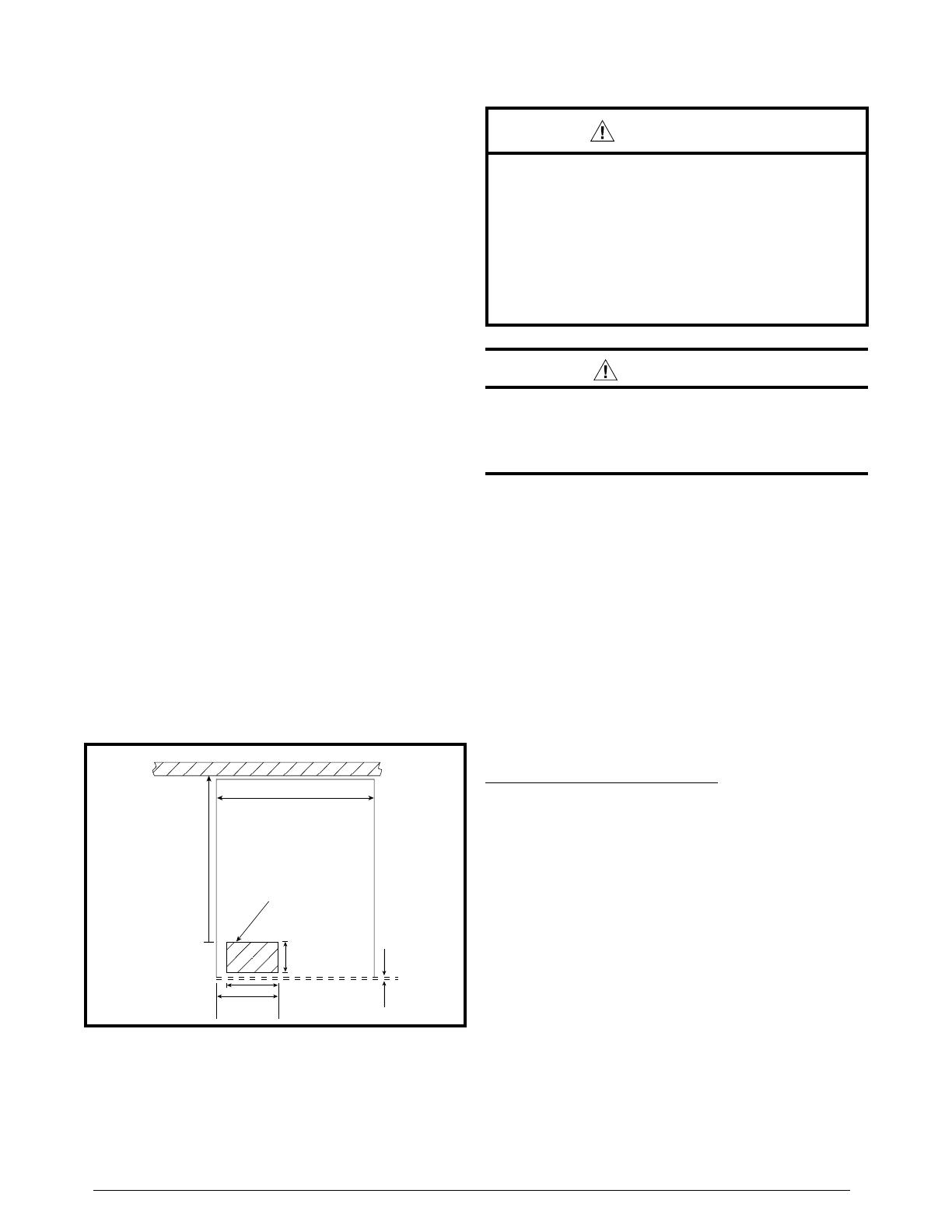
8. Cut the floor opening for the refrigerant lines and drain
line. See Figure 1.
9. Connect the refrigerant lines as outlined in the
Refrigerant Line Connection section (page 4).
20" (508 mm)
Floor Cut Out
for Refrigerant Lines
and Drain Hose
3 3/4"
(95 mm)
5 3/8"
(133 mm)
19 1/16"
(500 mm)
AIR HANDLER OUTLINE
REAR WALL (CLOSET OR ALCOVE)
3/4" (19 mm)
Furnace Outer Door
4 1/2" (114 mm) MAX
Figure 1. Location of Floor Cut-Out for
Refrigerant Lines & Drain Hoses
3
Downflow Furnace with Integral Coil Cabinet or
Optional Cabinet
1. Disconnect all electrical power to the furnace.
2. Remove the knockout in the left bottom corner of the
furnace and cut an appropriately sized hole in the floor.
See Figure 1. NOTE: For the optional cabinet, refer to
its installation instructions for assembly details.
3. Remove the interior coil panel. Install the coil and level
it as needed to ensure proper condensate drainage.
4. Remove the knockout for the refrigerant lines in the
secondary covers and replace in the furnace.
NOTE: Modifications to the panel may be required.
5. Slide the close-off plates around the refrigerant lines
and install the provided dart clips. See Figure 2.
6. Snap the bushings around the lines and into the close-
off panels.
7. Connect the refrigerant lines as outlined in the refrigerant
lines section.
Refrigerant Line Connections
The total system operating charge of R-410A is in the
outdoor unit and is adequate for the matched listed system
including 15 feet of line set.
CAUTION:
In orifice style coils before proceeding with the
connection of the refrigerant lines, confirm that
the orifice size meets the requirements outlined
in the outdoor unit installation manual.
Factory installed orifice sizes are listed in Table 2 (page
7). If the restrictor orifice must be replaced, see Restrictor
Change-Out section (page 5).
1. Remove the protective caps from the coil and refrigerant
line set couplings.
2. With a soft, dust-free cloth, carefully wipe clean all
coupling threads and seals to remove any dust or
material which could contaminate the refrigerant system.
3. Using refrigerant oil, lightly lubricate the diaphragm,
seal, and mating threads.
4. Connect the couplings as follows:
a.) Line up the refrigerant line with the coil coupling and
thread together by hand for 2-3 turns of the union
nut (or until a sharp increase in torque is felt), to
ensure proper thread mating.
b.) With the appropriate sized wrenches, tighten the
union nut while preventing rotation of the female
body with respect to the male half. Tighten the nut
to the appropriate value in Table 1.
c.) Mark the position of the union nut (match lines on
the line coupling and the coil coupling), then tighten
the coupling an additional one (1) wrench flat (60
degrees) to ensure a leakproof connection.
5. Check the system for leaks.
MOUNTING
HOLE
SMALL
PLATE
LARGE
PLATE
Figure 2. Close-Off Plate Assembly
Figure 3. Bottom Close-Off Plates
SMALL
PLATE
TAB
LARGE
PLATE
TABS
OFFSET
MOUNTING
HOLES (2)
TABS
Figure 4. Close-Off Plates for Opening
at Top of Furnace
SMALL
PLATE
LARGE
PLATE
TABS
MOUNTING
HOLE
OFFSET
Figure 5. Close-Off Plates
(Supplied w/ appropriate blower conversion
package)
COUPLING
SIZE
TORQUE
MALE
COUPLING
FEMALE
COUPLING
NUT
FEMALE
COUPLING
BODY
3/8”
(10mm)
10-12 Ft-Lbs
(14-16 Nm)
3/4” 13/16” 5/8”
3/4”
(19mm)
35-45 Ft-Lbs
(47-61 Nm)
1-1/16” 1-5/16” 1”
7/8”
(22mm)
35-45 Ft-Lbs
(47-61 Nm)
1-1/8” 1-5/16” 1”
Table 1. Torque Values
4
Figure 6. Loosening of Nut & Distributor Body
Install restrictor with
rounded end down
in the distributor
Figure 7. Restrictor Insertion into Distributor Body
Figure 8. Removal of Orifice
Carefully remove the
restrictor orifice from
the distributor body
Orifice Removal & Installation
If the orifice must be replaced, follow the steps below.
NOTE: Factory supplied orifice sizes are listed in Table
2 (page 7).
1. Connect only the suction line coupling to the coil
2. Reclaim the holding charge from the coil and suction
vapor line through the Schrader port using the methods
approved under the Refrigerant Transition and Recovery
Certification Program.
CAUTION:
To prevent damage to the unit or internal
components, it is recommended that two
wrenches be used when loosening or tightening
nuts. Do not over tighten!
3. Open the distributor body using two open end wrenches
and turning the swivel nut counterclockwise.
4. Insert a light-gauge wire hook between the distributor
body and the restrictor orifice while being careful not
to scratch either part. Carefully remove the restrictor
orifice from the distributor body. See Figure 7.
5. Select the proper size restrictor. The size is stamped on
its side. Do not use pin gauges to measure the orifice
diameter.
6. Insert the new orifice into the distributor body, rounded
end down. See Figure 8.
CAUTION:
To prevent damage to the unit or internal
components, it is recommended that two
wrenches be used when loosening or tightening
nuts. Do not over tighten!
7. Realign the assembly nut on the distributor body and
hand tighten both components. Mark a line on both
bodies and then tighten an additional 1/4 turn using two
wrenches. The movement of the two lines will show how
much the nut is tightened. If a torque wrench is used,
tighten to 10-12 ft. lbs. or 14-16 Nm.
8. Evacuate the system through the Schrader port on the
vapor line.
9. Connect the liquid line and check the connections for
leaks.
Condensate Drain
CAUTION:
The coil must be level to ensure proper condensate
drainage. Improper condensate disposal may
result in structural damage, premature equipment
failure, or possible personal injury.
Methods for disposing of condensate vary according
to local codes. Refer to local codes or authority having
jurisidiction for restrictions and proper condensate
disposal requirements.
5
All condensate pans have primary and secondary drain
connections to meet FHA requirements. If the application
is located in or above a living space where damage
may result from condensate overflow, a separate 3/4
inch drain must be provided from the secondary drain
connection and a secondary drain pan must be installed
under the entire unit. Run secondary drain lines to a
place where they are noticeable if used.
The coil condensate pan is designed with 3/4” NPSC
drain connections. Use a PVC or similar material fitting
to attach the drain line to the pan. NOTE: The fitting
should be hand tightened only. Overtightening may
crack the drain pan and cause condensate to leak.
The drain pan MUST be drained with field supplied
tubing and looped to form a trap.
IMPORTANT: Failure to install a trap may result in
condensation overflowing the drain pan, resulting in
substantial water damage to surrounding area.
Prime the trap with water. Insulate the drain if it is located
in an unconditioned space, and test the condensate line
for leaks. Consult local codes for additional restrictions
or precautions.
Route the lines to a suitable drain, avoiding sharp bends
and pinching of the lines. The drain should maintain a
minimum horizontal slope in the direction of discharge
of not less than 1” vertical for every 10 ft of horizontal
run.
During system checkout, inspect the drain line and
connections to verify proper condensate drainage.
Air Filter
Air filters are not supplied as an integral part of this
coil; however, an air filter kit is available. Refer to the
Replacement Parts List for available part numbers.
The filter must be installed upstream of the coil and
inspected frequently. When the filter becomes clogged
with dust or lint, it should be replaced (disposable type)
or cleaned (washable type). It is recommended that filters
be inspected and replaced at least twice during the year.
Generally it is best to replace or clean the filters at the
start of each heating and cooling season.
MAINTENANCE & SERVICE
WARNING:
ELECTRICAL SHOCK OR FIRE HAZARD
To avoid risk of electrical shock, personal injury,
or death, disconnect all electrical power to the unit
before performing any maintenance or service. The
unit may have more than one electrical supply.
Label all wires prior to disconnection when servicing
the unit. Wiring errors can cause improper and
dangerous operation
CAUTION:
Do not operate the system without a suitable filter
in the return air duct system. Always replace the
filter with the same size and type.
To ensure optimum performance and to minimize possible
equipment failure, the following maintenance tasks should
be performed periodically on this equipment:
1. The air filter installed with the system should be checked
and cleaned or replaced twice per year.
2. Check the coil, drain pan, and condensate drain line
for cleanliness at the start of each heating and cooling
season. Clean as needed.
6
Figure 9. C8QA Coil Dimensions
2 1/2”
W
19 1/2”
1 3/8”
1”
12 1/8”
14 1/2”
H
Table 1. Coil Specifications
C8QA- 024 030 036 042 048
Nominal Capacity (BTUH) 24,000 30,000 36,000 42,000 48,000
Nominal Airflow (CFM) 800 1,000 1,200 1,400 1,600
W - Width (in.) 18 1/8 18 1/8 18 1/8 18 1/8 18 1/8
H - Height (in.) 18 18 18 24 3/4 24 3/4
D - Depth (in.) 19 1/2 19 1/2 19 1/2 19 1/2 19 1/2
Connection - Liquid Line (in.) 3/8 3/8 3/8 3/8 3/8
Connection - Suction Line (in.) 3/4 3/4 3/4 3/4 3/4
Installed Orifice Size (in.) .055 .061 .067 .072 .077
NOTES:
1. Individual restrictors are available by part number - PN664*** (where *** represents the size).
Example: 664103 is a restrictor 0.103 in diameter.
2. Refer to sales specification sheets for Listed / Certified combinations of equipment and required accessories.
3. Refer to the current AHRI directory for certified ratings of split systems.
COIL SPECIFICATIONS & DIMENSIONS
7
Specifications & illustrations subject to change without notice or incurring obligations (10/20).
O’Fallon, MO, © Nortek Global HVAC LLC 2020. All Rights Reserved.
10358350
(Replaces 709280B)
INSTALLER: PLEASE LEAVE THESE INSTRUCTIONS WITH THE EQUIPMENT OWNER.
  • Page 1 1
  • Page 2 2
  • Page 3 3
  • Page 4 4
  • Page 5 5
  • Page 6 6
  • Page 7 7
  • Page 8 8

Broan C8QA Installation guide

Category
Split-system air conditioners
Type
Installation guide

Ask a question and I''ll find the answer in the document

Finding information in a document is now easier with AI