


i
Motherboard User’s Guide
This publication, including photographs, illustrations and software, is under the
protection of international copyright laws, with all rights reserved. Neither this
user’s guide, nor any of the material contained herein, may be reproduced
without the express written consent of the manufacturer.
The information in this document is subject to change without notice. The
manufacturer makes no representations or warranties with respect to the
contents hereof and specifically disclaims any implied warranties of merchant-
ability or fitness for any particular purpose. Further, the manufacturer reserves
the right to revise this publication and to make changes from time to time in the
content hereof without obligation of the manufacturer to notify any person of
such revision or changes.
Trademarks
IBM, VGA, and PS/2 are registered trademarks of International Business
Machines.
Intel, Pentium/II/III, Pentium 4, Celeron D, Pentium D and MMX are registered
trademarks of Intel Corporation.
Microsoft, MS-DOS and Windows 98SE/ME/2000/XP are registered trademarks
of Microsoft Corporation.
AMI is a trademark of American Megatrends Inc.
It has been acknowledged that other brands or product names in this manual are
trademarks or the properties of their respective owners.
Static Electricity Precautions
1. Don’t take this motherboard and components out of their original static-
proof package until you are ready to install them.
2. While installing, please wear a grounded wrist strap if possible. If you
don’t have a wrist strap, discharge static electricity by touching the bare
metal of the system chassis.
3. Carefully hold this motherboard by its edges. Do not touch those
components unless it is absolutely necessary. Put this motherboard on
the top of static-protection package with component side facing up
while installing.
Pre-Installation Inspection
1. Inspect this motherboard whether there are any damages to components
and connectors on the board.
2. If you suspect this motherboard has been damaged, do not connect
power to the system. Contact your motherboard vendor about those
damages.
Copyright © 2006
All Rights Reserved
P27G Series, V3.0
June 2006

ii
Motherboard User’s Guide
Table of Contents
Trademark............................................................................................................i
Static Electricity Precautions ......................................................................................... i
Pre-Installation Inspection............................................................................................. i
Chapter 1: Introduction..................................................................................... 1
Key Features.................................................................................................................... 1
Package Contents ........................................................................................................... 4
Chapter 2: Motherboard Installation .............................................................. 5
Motherboard Components ............................................................................................ 6
I/O Ports .......................................................................................................................... 7
Installing the Processor ................................................................................................. 7
Installing Memory Modules .......................................................................................... 9
Jumper Settings ............................................................................................................12
Install the Motherboard ...............................................................................................13
Connecting Optional Devices .....................................................................................14
Install Other Devices ....................................................................................................16
Expansion Slots ............................................................................................................18
Chapter 3: BIOS Setup Utility....................................................................... 19
Introduction ..................................................................................................................19
Running the Setup Utility ...................................................…………………………...19
Standard CMOS Setup Page.......................................................................................20
Advanced Setup Page ..................................................................................................21
Features Setup Page ....................................................................................................23
Power Management Setup ..........................................................................................24
PCI/Plug and Play Setup Page ..................................................................................25
BIOS Security Features Setup Page...........................................................................26
CPU PnP Setup Page ..................................................................................................27
Hardware Monitor Page..............................................................................................28
Load Optimal Defaults ................................................................................................28
Save Changes and Exit ................................................................................................29
Discard Changes and Exit...........................................................................................29
Chapter 4: Software & Applications ..............................................................31
Introduction ..................................................................................................................31
Installing Support Software ........................................................................................31
Bundled Software Installation ....................................................................................33
AMI/AWARD Flash Utility ...........................................................................................33
WinFlash Utility .............................................................................................................33

iii
Motherboard User’s Guide
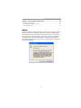
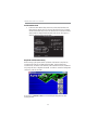
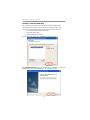
Notice:
Owing to Microsoft’s certifying schedule is various to every supplier, we might
have some drivers not certified yet by Microsoft. Therefore, it might happen
under Windows XP that a dialogue box (shown as below) pop out warning you
this software has not passed Windows Logo testing to verify its compatibility
with Windows XP. Please rest assured that our RD department has already
tested and verified these drivers. Just click the “Continue Anyway” button and
go ahead the installation.
Chapter 5: VIA VT8237 RAID Setup Guide .................................................. 35
VIA RAID Configuration .............................................................................................35
Installing RAID Software & Drivers...........................................................................43
Using VIA RAID Tool ...................................................................................................45

1
Chapter 1: Introduction
Chapter 1 Introduction
This motherboard has an LGA775 socket for the latest Intel® Core™2 Duo/
Pentium D/Pentium 4/ Celeron D processors with Hyper-Threading Technology
and Front-Side Bus (FSB) speeds up to 1066/800/533 MHz. Hyper-Threading
Technology, designed to take advantage of the multitasking features in Windows
XP, gives you the power to do more things at once.
It integrates the VIA P4M800Pro Northbridge and VT8237R Plus Southbridge
that supports the Serial ATA interface for high-performance and mainstream
desktop PCs; the built-in USB 2.0 providing higher bandwidth, implementing
Universal Serial Bus Specification Revision 2.0 and is compliant with UHCI 1.1
and EHCI 1.0. It supports AC’ 97 Audio Codec and provides Ultra DMA 133/
100/66 function. It has one 8X AGP, one CNR and three 32-bit PCI slots. There
is a full set of I/O ports including two PS/2 ports for mouse and keyboard, one
serial port, one parallel port, one VGA port, one LAN port (optional), three
audio jacks for Line-in, Line-out and Microphone, four back-panel USB 2.0
ports and onboard USB headers providing extra ports by connecting the
Extended USB Module to the motherboard.
It is a Micro ATX motherboard and has power connectors for an ATX power
supply.
Key Features
The key features of this motherboard include:
LGA775 Socket
• Supports the latest Intel® Core™2 Duo/Pentium D/Pentium 4/Celeron
D Series processors with Hyper-Threading Technology
• Supports up to 1066/800/533 MHz Front-Side Bus
Hyper-Threading technology enables the operating system into thinking it’s
hooked up to two processors, allowing two threads to be run in parallel, both
on separate ‘logical’ processors within the same physical processor.
Chipset
There are VIA P4M800Pro Northbridge and VT8237R Plus in the chipsets in
accordance with an innovative and scalable architecture with proven reliability
and performance.
• High Performance Northbridge with 1066/800/533 MHz FSB for Intel®
Core™2 Duo/Pentium D/Pentium 4/Celeron D processors
• V-link 533 MB/s high bandwidth North/South Bridge interconnect
• Integrated UniChrome Pro 3D/2D Graphics & Video Controller,
Microsoft DirectX 9.0 compatible, OpenGL supported

2
Motherboard User’s Guide
• Supports for AGP 8X/4X, AGP v3.0 compliant with 1.5V
• Advanced 64-bit DDR2 533 SDRAM controller
Note: P4M800Pro chipset can only support mixed 1024/512/256/128/
64Mb x8/16 DDR2 SDRAMs.
• Supports 16-bit 66 MHz V-Link Host interface with total bandwidth of
1066 MB/s
• Compliant with PCI 2.2 specification at 33 MHz, supporting up to 6
PCI masters
• Integrated Serial ATA Host Controllers, supporting data transfer rates up
to 1.5Gb/s
• Integrated Dual channel UltraDMA 133/100/66 Master Mode EIDE
Controller
• USB 2.0 Controller, supporting up to 8 USB 2.0 ports
• Network Controller, supporting enterprise class 100/10 Mb Fast
Ethernet MAC
• Integrated keyboard Controller with PS2 mouse support
Memory Support
• Two 240-pin DIMM sockets for DDR2 SDRAM memory modules
• Support DDR2 533 DDR2 SDRAM with Maximum memory size of 2
GB.
Expansion Slots
• Three 32-bit PCI slots
• One 8X AGP slot
• One CNR slot
Onboard IDE channels
• Supports PIO (Programmable Input/Output) and DMA (Direct Memory
Access) modes
• Supports IDE Ultra DMA bus mastering with transfer rates of 133/100/
66 MB/sec
Serial ATA
• Two Serial ATA Connectors
• Transfer rate exceeding best ATA (~150 MB/s) with scalability to higher
rates
• Low pin count for both host and devices
AC’97 Audio Codec
• Compliant with AC’97 2.3 specifications
• Meets performance requirements for audio on PC99/2001 systems
• Meets Microsoft WHQL/WLP 2.0 audio requirements

3
Chapter 1: Introduction
• Support 48 KHz of S/PDIF output is compliant with AC’97 rev2.3
specification
• HRTF 3D Positional Audio and 10 Bands of Software EQualizer
Onboard I/O Ports
• Two PS/2 ports for mouse and keyboard
• One serial port
• One parallel port
• One VGA port
• One LAN port (optional)
• Four back-panel USB2.0 ports
• Audio jacks for microphone, line-in and line-out
Fast Ethernet LAN (optional)
• Single Chip 100Base-TX / 10Base-T Physical Layer Solution
• Dual Speed – 100/10 Mbps
• Half and Full Duplex
• MII Interface to Ethernet Controller
• MII Interface to Configuration & Status
• Auto Negotiation: 10 / 100, Full / Half Duplex
• Meet All Applicable IEEE 802.3, 10Base-T and 100Base-Tx Standards.
• On Chip Wave Shaping – No External Filters Required.
USB 2.0
• Compliant with Universal Serial Bus Specification Revision 2.0
• Compliant with Intel’s Enhanced Host Controller Interface Specification
Revision 1.0
• Compliant with Universal Host Controller Interface Specification Revision
1.1
• PCI multi-function device consists of two UHCI Host Controller cores for
full-/low-speed signaling and one EHCI Host Controller core for high-
speed signaling
• Root hub consists 4 downstream facing ports with integrated physical
layer transceivers shared by UHCI and EHCI Host Controller, up to eight
functional ports
• Support PCI-Bus Power Management Interface Specification release 1.1
• Legacy support for all downstream facing ports
BIOS Firmware
This motherboard uses AMI BIOS that enables users to configure many system
features including the following:
• Power management
• Wake-up alarms
• CPU parameters and memory timing
• CPU and memory timing

4
Motherboard User’s Guide
Note: Hardware specifications and software items are subject to change
without notification.
The firmware can also be used to set parameters for different processor clock
speeds.
Dimensions
• Micro ATX form factor of 244 x 220 mm
Package Contents
Your motherboard package ships with the following items:
The motherboard
The User’s Guide
One diskette drive ribbon cable (optional)
One IDE drive ribbon cable
The Software support CD
Optional Accessories
You can purchase the following optional accessories for this motherboard.
The Extended USB module
The CNR v.90 56 K Fax/Modem card
The Serial ATA cable
The Serial ATA power cable
Note: You can purchase your own optional accessories from the third party,
but please contact your local vendor on any issues of the specification
and compatibility.

5
Chapter 2: Motherboard Installation
Chapter 2 Motherboard Installation
To install this motherboard in a system, please follow these instructions in this
chapter:
Identify the motherboard components
Install a CPU
Install one or more system memory modules
Make sure all jumpers and switches are set correctly
Install this motherboard in a system chassis (case)
Connect any extension brackets or cables to headers/connectors on the
motherboard
Install peripheral devices and make the appropriate connections to
headers/connectors on the motherboard
Note:
1. Before installing this motherboard, make sure jumper CLR_CMOS1
is under Normal setting. See this chapter for information about
locating CLR_CMOS1 and the setting options.
2. Never connect power to the system during installation; otherwise, it
may damage the motherboard.

6
Motherboard User’s Guide
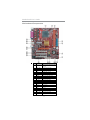
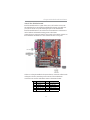
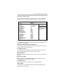
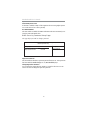
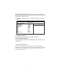
Motherboard Components
ITEM LABEL COMPONENTS
1 CPU Socket
LGA775 Socket for Intel Core
™2 Duo
Pentium 4/ Celeron D/Pentium D
processors
2 CPU_FAN1 CPU Fan connector(4-pin)
3 DDRII1-2 240-pin DDR2 SDRAM sockets
4 IDE1 Primary IDE connector
5 IDE2 Secondary IDE connector
6 SATA1/2 Serial ATA connectors
7 CLR_CMOS1 Clear CMOS jumper
8 PANEL1 Front Panel Switch/LED header
9 SPK1 Speaker header
10 SYS_FAN1 System Fan connector
11 F_USB1/2 Front Panel USB headers
12 FDD1 Floppy Disk Drive connector
13 CNR1 CNR slot
14 IR1 Infrared header
15 PCI 1-3 32-bit PCI slots
16 CD_IN1 Analog Audio Input header
17 AGP1 AGP slot
18 F_AUDIO1 Front Panel Audio header
19 PWR1 Standard 20-Pin ATX Power connector
20 USB_PWR1 USB Power Select jumper
21 ATX_12V1 Standard 4-Pin ATX Power connector

7
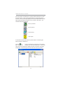
Chapter 2: Motherboard Installation
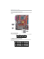
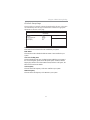
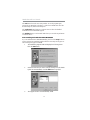
I/O Ports
The illustration below shows a side view of the built-in I/O ports on the
motherboard.
PS/2 Mouse
Use the upper PS/2 port to connect a PS/2 pointing
device.
PS/2 Keyboard
Use the lower PS/2 port to connect a PS/2
keyboard.
Parallel Port (LPT1)
Use the Parallel port to connect printers or other
parallel communications devices.
COM1
Use the COM port to connect serial devices such
as mice or fax/modems. COM1 is identified by the
system as COM1.
VGA
Use the VGA port to connect VGA devices.
LAN Port (optional)
Connect an RJ-45 jack to the LAN port to connect
your computer to the Netw ork.
USB Ports
Use the USB ports to connect USB devices.
Audio Ports
Use these three audio jacks to connect audio
devices. The first jack is for stereo Line-In signal,
the second jack for stereo Line-Out signal, and the
third jack for Microphone.
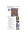
Installing the Processor
This motherboard has an LGA775 socket for the latest Intel Core ™2 Duo/
Pentium D/Pentium 4/Celeron D processors. When choosing a processor,
consider the performance requirements of the system. Performance is based on
the processor design, the clock speed and system bus frequency of the proces-
sor, and the quantity of internal cache memory and external cache memory.

8
Motherboard User’s Guide
CPU Installation Procedure
Follow these instructions to install the CPU:
A. Read and follow the instructions shown on
the sticker on the CPUcap.
Close the load plate
Fasten the cooling fan supporting base
onto the CPU socket on the motherboard.
F. Apply thermal grease on top of the CPU.
E.
• Slightly push down the load plate onto
the tongue side, and hook the lever.
• CPU is locked completely.
G..
B. Unload the cap
• Use thumb & forefinger to hold the
lifting tab of the cap.
• Lift the cap up and remove the cap
completely from the socket.
C. Open the load plate
• Use thumb & forefinger to hold the
hook of the lever, pushing down and
pulling aside unlock it.
• Lift up the lever.
• Use thumb to open the load plate.
Be careful not to touch the contacts.
D. Install the CPU on the socket
• Orientate CPU package to the socket.
• Make sure you match triangle marker
to pin 1 location.

9
Chapter 2: Motherboard Installation
Installing Memory Modules
This motherboard accommodates two 240-pin DIMM DDRII1~2 sockets (Dual
Inline Memory Module) for unbuffered DDR2 533 memory modules (Double
Data Rate SDRAM). DDR2 SDRAM is a type of SDRAM that supports data
transfers on both edges of each clock cycle (the rising and falling edges),
effectively doubling the memory chip’s data throughput. You must install at least
one module in any of the two slots. Each module can be installed with 256 MB
to 1 GB of memory; total memory capacity is 2 GB.
H. Make sure the CPU fan is plugged to the
CPU fan connector. Please refer to the
CPU cooling fan user’s manual for more
detail installation procedure.
Note 1: To achieve better airflow rates and heat dissipation, we suggest
that you use a high quality fan with 3800 rpm at least. CPU fan and
heatsink installation procedures may vary with the type of CPU fan/
heatsink supplied. The form and size of fan/heatsink may also vary.
Note 2: DO NOT remove the CPU cap from the socket before installing a
CPU.
Note 3: Return Material Authorization(RMA) requests will be accepted only if
the motherboard comes with the cap on the LGA775 socket.

10
Motherboard User’s Guide
Note1: Do not remove any memory module from its antistatic packaging until
you are ready to install it on the motherboard. Handle the modules
only by their edges. Do not touch the components or metal parts.
Always wear a grounding strap when you handle the modules.
Memory Module Installation Procedure
These modules can be installed with up to 2 GB system memory. Refer to the
following to install the memory module.
1. Push down the latches on both sides of the DIMM socket.
2. Align the memory module with the socket. There is a notch on the
DIMM socket that you can install the DIMM module in the correct
direction. Match the cutout on the DIMM module with the notch on
the DIMM socket.
3. Install the DIMM module into the socket and press it firmly down
until it is seated correctly. The socket latches are levered upwards and
latch on to the edges of the DIMM.
4. Install any remaining DIMM modules.

11
Chapter 2: Motherboard Installation
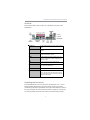
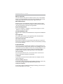
Table A: DDR2 (memory module) QVL (Qualified Vendor List)
The following DDR2 533 memory modules have been tested and qualified for use with
this motherboard.
Size Vendor Module Name
AENEON
AET560UD00-370A98X
AENEON AET560UD00-370A98Z
CORSAIR 4PB11D9CHM
ELPIDA 04180WB00
Elixir N2TU51216AF-37B
ELPIDA E2508AA-DF-E
256 MB
SAMSUNG K4T56083QF-GCCC
A-DATA M2GXX2F3H4140A1B0E
ADATA Eipida E5108AE-6E-E
AENEON AET660UD00-370A98X
AENEON AET660UD00-370A98Z
CORSAIR CM2X512-4200
CORSAIR 4PB11D9CHM
ELPIDA E2508AA-DF-E
G.SKILL G76 GT
Infinity 0547W64M9PC5300
Kingston KVR533D2N4/512HYPS56821
PQI PQC2648S3
Samsung K4T56083QF
SAMSUNG K4T51083QB-GCCC
SAMSUNG K4T51083QB-GCD5
SyncMAX 64MX8 D2-F
Transcend K4T5108AE-6E-E
512MB
Twinmos Elpida 8D22JB-ED
AENEON AET03F50C
Kingston D6408TE8EWL3
1GB
Kingston NANTA NT5TU64MBAE-378

12
Motherboard User’s Guide
Jumper Settings
Connecting two pins with a jumper cap is SHORT; removing a jumper cap from
these pins, OPEN.
Note: To avoid the system unstability after clearing CMOS, we recommend
users to enter the main BIOS setting page to “Load Optimal De-faults”
and then “Save Changes and Exit”.
CLR_COMS1: Clear CMOS Jumper
Use this jumper to clear the contents of the CMOS memory. You may need to
clear the CMOS memory if the settings in the Setup Utility are incorrect and
prevent your motherboard from operating. To clear the CMOS memory,
disconnect all the power cables from the motherboard and then move the jumper
cap into the CLEAR setting for a few seconds.
Function Jumper Setting
Normal Short Pins 1-2
Clear CMOS Short Pins 2-3
Note: Make sure the power supply provides enough SB5V voltage before
selecting the SB5V function.
USB_PWR1: USB Power Select Jumper
Use these jumpers to select the voltage for USB port.
Function Jumper Setting
VCC5V Short Pins 1-2
SB5V Short Pins 2-3

13
Chapter 2: Motherboard Installation
Install the Motherboard
Install the motherboard in a system chassis (case). The board is a Micro ATX
size motherboard. You can install this motherboard in an ATX case. Make sure
your case has an I/O cover plate matching the ports on this motherboard.
Install the motherboard in a case. Follow the case manufacturer’s instructions to
use the hardware and internal mounting points on the chassis.
Connect the power connector from the power supply to the PWR1 connector on
the motherboard. The PWR2 is a +12V connector for CPU Vcore power.
Pin Signal Pin Signal
1 HD_LED_P (+) 2 SOS_LED_P (+)
3 HD_LED_N (-) 4 SOS_LED_N (-)
5 RESET_SW_N (-) 6 POWER_SW_P (+)
7 RESET_SW_P (+) 8 POWER_SW_N (-)
9 RSVD_DNU 10 KEY
If there is a cooling fan installed in the system chassis, connect the cable from the
cooling fan to the SYS_FAN1 fan power connector on the motherboard.
Connect the case switches and indicator LEDs to the PANEL1 header.

14
Motherboard User’s Guide
Connecting Optional Devices
Refer to the following for information on connecting the motherboard’s optional
devices:
Pin Signal Pin Signal
1SPKR2 NC
3GND4+5V
SPK1: Speaker Header
Connect the cable from the PC speaker to the SPK1 header on the motherboard.
F_AUDIO1: Front Panel Audio Header
This header allows the user to install auxiliary front-oriented microphone and
line-out ports for easier access.
Pin Signal Pin Signal
1 AUD_MIC 2 AUD_GND
3 AUD_MIC_BIAS 4 A UD_VCC
5 AUD_FPOUT_R 6 AUD_RET_R
7HP_ON 8KEY
9 AUD_FPOUT_L 10 A UD_RET_L

15
Chapter 2: Motherboard Installation
Pin Signal Pin Signal
1 V ERG_FP_USBPWR0 2 V ERG_FP_USBPWR0
3 USB_FP_P0(-) 4 USB_FP_P1(-)
5 USB_FP_P0(+) 6 USB_FP_P1(+)
7 GROUND 8 GROUND
9 KEY 10 USB_FP_OC0
F_USB1/F_USB2: Front panel USB Headers
The motherboard has USB ports installed on the rear edge I/O port array.
Additionally, some computer cases have USB ports at the front of the case. If
you have this kind of case, use auxiliary USB headers F_USB1/F_USB2 to
connect the front-mounted ports to the motherboard.
1. Locate the F_USB1/F_USB2 header on the motherboard.
2. Plug the bracket cable onto the F_USB1/F_USB2 header.
3. Remove a slot cover from one of the expansion slots on the system
chassis. Install an extension bracket in the opening. Secure the
extension bracket to the chassis with a screw.
IR1: Infrared Header
The infrared port allows the wireless exchange of information between your
computer and similarly equipped devices such as printers, laptops, Personal
Digital Assistants (PDAs), and other computers.
1. Locate the infrared port-IR1 header on the motherboard.
2. If you are adding an infrared port, connect the ribbon cable from the
port to the IR1 header and then secure the port to an appropriate
place in your system chassis.
Pin Signal Pin Signal
1NC2KEY
3+5V4GND
5 IRTX 6 IRRX
Page is loading ...
Page is loading ...
Page is loading ...
Page is loading ...
Page is loading ...
Page is loading ...
Page is loading ...
Page is loading ...
Page is loading ...
Page is loading ...
Page is loading ...
Page is loading ...
Page is loading ...
Page is loading ...
Page is loading ...
Page is loading ...
Page is loading ...
Page is loading ...
Page is loading ...
Page is loading ...
Page is loading ...
Page is loading ...
Page is loading ...
Page is loading ...
Page is loading ...
Page is loading ...
Page is loading ...
Page is loading ...
Page is loading ...
Page is loading ...
Page is loading ...
Page is loading ...
Page is loading ...
-
 1
1
-
 2
2
-
 3
3
-
 4
4
-
 5
5
-
 6
6
-
 7
7
-
 8
8
-
 9
9
-
 10
10
-
 11
11
-
 12
12
-
 13
13
-
 14
14
-
 15
15
-
 16
16
-
 17
17
-
 18
18
-
 19
19
-
 20
20
-
 21
21
-
 22
22
-
 23
23
-
 24
24
-
 25
25
-
 26
26
-
 27
27
-
 28
28
-
 29
29
-
 30
30
-
 31
31
-
 32
32
-
 33
33
-
 34
34
-
 35
35
-
 36
36
-
 37
37
-
 38
38
-
 39
39
-
 40
40
-
 41
41
-
 42
42
-
 43
43
-
 44
44
-
 45
45
-
 46
46
-
 47
47
-
 48
48
-
 49
49
-
 50
50
-
 51
51
-
 52
52
-
 53
53


Ask a question and I''ll find the answer in the document
Finding information in a document is now easier with AI
Related papers
Other documents
-
 StarTech.com PEXSAT2IDE2 Datasheet
-
PC CHIPS P29G (V1.0) User guide
-
-
-
-
Kanguru MicroDrive AES Quick start guide
-
Digitus DS-33150-1 Datasheet
-
Foxconn VT8237R PLUS User manual
-
Sitecom CN-033 Datasheet
-
DeLOCK 70096 Datasheet
