Page is loading ...
Page is loading ...

i
Motherboard User’s Guide
This publication, including photographs, illustrations and software,
is under the protection of international copyright laws, with all
rights reserved. Neither this manual, nor any of the material
contained herein, may be reproduced without the express written
consent of the manufacturer.
The information in this document is subject to change
without notice. The manufacturer makes no representations or
warranties with respect to the contents hereof and specifically
disclaims any implied warranties of merchantability or fitness for
any particular purpose. Further, the manufacturer reserves the
right to revise this publication and to make changes from time to
time in the content hereof without obligation of the manufacturer
to notify any person of such revision or changes.
Trademarks
IBM, VGA, and PS/2 are registered trademarks of International
Business Machines.
Intel, Pentium/II/III, Pentium 4, Celeron and MMX are registered
trademarks of Intel Corporation.
Microsoft, MS-DOS and Windows 98/ME/NT/2000/XP are
registered trademarks of Microsoft Corporation.
PC-cillin is a trademark of Trend Micro Inc.
AMI is a trademark of American Megatrends Inc.
It has been acknowledged that other brands or product names in
this manual are trademarks or the properties of their respective
owners.
Copyright © 2004
All Rights Reserved
T12 Series, V1.1
I865PE/May 2004

ii
Motherboard User’s Guide
Table of Contents
Trademark ................................................................................... i
Features and Checklist Translation........................................ v
Chapter 1: Introduction............................................................ 1
Key Features ........................................................................................2
Package Contents ................................................................................6
Chapter 2: Mainboard Installation.......................................... 7
Mainboard Components ......................................................................8
I/O Ports ............................................................................................... 9
Installing the Processor .....................................................................10
Installing Memory Modules ............................................................... 11
Jumper Settings ..................................................................................13
Install the Motherboard.....................................................................14
Connecting Optional Devices............................................................15
Install Other Devices..........................................................................17
Expansion Slots..................................................................................20
Chapter 3: BIOS Setup Utility............................................... 22
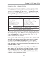
Introduction .......................................................................................22
Running the Setup Utility ........................... …………………………...23
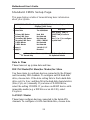
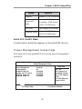
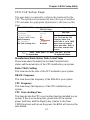
Standard CMOS Setup Page .............................................................24
Advanced Setup Page ........................................................................25
Features Setup Page ..........................................................................27
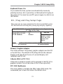
Power Management Setup Page........................................................29
PCI/Plug and Play Setup Page..........................................................31
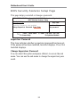
BIOS Security Features Setup Page ..................................................32
CPU PnP Setup Page .........................................................................33
Hardware Monitor Page....................................................................34
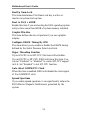
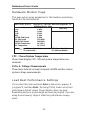
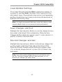
Load Best Performance Settings ........................................................34
Load Optimal Defaults .......................................................................35
Save Changes and Exit ......................................................................35
Discard Changes and Exit .................................................................35
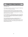
Chapter 4: Software & Applications ..................................... 36
Introduction .......................................................................................36
Installing Support Software...............................................................37
Bundled Software Installation...........................................................39
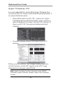
Hyper Threading CPU .......................................................................40

iii
Motherboard User’s Guide
Static Electricity Precautions
Static electricity could damage components on this motherboard.
Take the following precautions while unpacking this motherboard
and installing it in a system.
1. Don’t take this mainboard and components out of their
original static-proof package until you are ready to install
them.
2. While installing, please wear a grounded wrist strap if
possible. If you don’t have a wrist strap, discharge static
electricity by touching the bare metal of the system chassis.
3. Carefully hold this motherboard by its edges. Do not touch
those components unless it is absolutely necessary. Put this
motherboard on the top of static-protection package with
component side facing up while installing.
Pre-Installation Inspection
1. Inspect this mainboard whether there are any damages to
components and connectors on the board.
2. If you suspect this mainboard has been damaged, do not
connect power to the system. Contact your motherboard
vendor about those damages.

iv
Motherboard User’s Guide
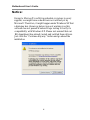
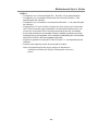
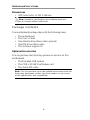
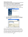
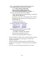
Notice:
Owing to Microsoft’s certifying schedule is various to every
supplier, we might have some drivers not certified yet by
Microsoft. Therefore, it might happen under Windows XP that
a dialogue box (shown as below) pop out warning you this
software has not passed Windows Logo testing to verify its
compatibility with Windows XP. Please rest assured that our
RD department has already tested and verified these drivers.
Just click the “Continue Anyway” button and go ahead the
installation.
Page is loading ...
Page is loading ...
Page is loading ...
Page is loading ...
Page is loading ...
Page is loading ...
Page is loading ...
Page is loading ...
Page is loading ...
Page is loading ...
Page is loading ...
Page is loading ...
Page is loading ...
Page is loading ...
Page is loading ...
Page is loading ...
Page is loading ...
Page is loading ...

1
Chapter 1: Introduction
Chapter 1 Introduction
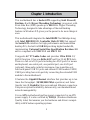
This motherboard has a Socket-478 supporting Intel Prescott/
Pentium 4 with Hyper-Threading Technology processors with
Front-Side Bus (FSB) speeds up to 800 MHz. Hyper-Threading
Technology, designed to take advantage of the multitasking
features in Windows XP, gives you the power to do more things at
once.
This motherboard integrates the Intel 865PE Northbridge along
with Intel 82801EB I/O Controller Hub (ICH5) that support
the Serial ATA interface for high-performance and mainstream
desktop PCs; the built-in USB 2.0 providing higher bandwidth,
implementing Universal Serial Bus Specification Revision 2.0
and is compliant with UHCI 1.1 and EHCI 1.0.
It supports AC’97 Audio Codec and provides Ultra DMA 33/
66/100 function. It has one 8x/4x AGP and five 32-bit PCI slots.
There is a full set of I/O ports including two PS/2 ports for mouse
and keyboard, one serial port, one parallel port, one LAN port
(optional), three audio jacks for micropone, line-in and line-out,
four back-panel USB 2.0 ports and onboard USB headers USB2/
USB3 providing four extra ports by connecting the extended USB
module to the motherboard.
It features the Gigabit Ethernet interface that provides up to ten
times the throughput (10/100/1000 Mb/s operation) and faster
transfer rate (1 Gigabit/s) than conventional Ethernet connection.
It improves system availability, data security, user bandwidth and
network manageability.
It is an ATX motherboard and has power connectors for an ATX
power supply. It is also certified by WHQL (Windows Hardware
Quality Labs) that ensures you the hardware and drivers compat-
ibility with Windows operating systems.

2
Motherboard User’s Guide
Note: You must initiate the HT CPU function through BIOS setup. It is
strongly recommended you refer to Page 40 for relative details.
Key Features
The key features of this motherboard include:
Socket-478 Processor Support
• Supports Intel Prescott/Pentium 4 Series processors
with Hyper-Threading Technology
• Supports up to 800 MHz Front-Side Bus
Hyper-Threading technology enables the operating system
into thinking it’s hooked up to two processors, allowing two
threads to be run in parallel, both on separate ‘logical’
processors within the same physical processor.
Chipset
There are Intel 865PE Northbridge and Intel 82801EB I/O
Controller Hub (ICH5) in the chipsets in accordance with an
innovative and scalable architecture with proven reliability and
performance.
• Supports either an integrated graphics device (IGD) or an
external graphics device on AGP. The AGP interface
supports 1X/4X/8X AGP data transfers and 4X/8X AGP
Fast Writes.
• Supports 4 GB of system memory and has a maximum
bandwidth of 6.4 GB/s using DDR400 in dual-channel
mode.
• Integrates an Ultra ATA 100 controller, two Serial ATA host
controllers, one EHCI host controller, and four UHCI host
controllers supporting eight external USB 2.0 ports.
• PCI Bus Interface: supports PCI Revision 2.3 Specification
• Integrated LAN Controller: WfM 2.0 and IEEE802.3
Compliant

3
Chapter 1: Introduction
• Integrated Serial ATA Host Controller: Independent DMA
operation and Data Transfer Rate up to 1.5Gb/s(150MB/s)
Memory Support
• Four 184-pin DIMM sockets for DDR SDRAM memory
modules
• Supports DDR400 memory bus
• Maximum installed memory is 4GB
Expansion Slots
• One CNR slot
• One 8x/4x AGP slot
• Five 32-bit PCI slots for PCI 2.3-compliant bus interface
Onboard IDE channels
• Two IDE Connectors
• Supports PIO (Programmable Input/Output) and DMA
(Direct Memory Access) modes
• Supports IDE Ultra DMA bus mastering with transfer rates
of 33/66/100 MB/sec
Serial ATA
• Two Serial ATA Connectors
• Transfer rate exceeding best ATA (~150 MB/s) with
scalability to higher rates
• Low pin count for both host and devices
AC’97 Codec
• 6-CH hardware architecture allows multi-channel south
bridge to playback 6CH audio
• Intel
®
AC’97 (REV. 2.3) compatible, meeting Microsoft
®
PC2001 requirements
• Built-in earphone buffer and internal PLL, the latter saving
additional crystal
• Line-in/rear out share the same jack; Center/bass share the
MIC jack

4
Motherboard User’s Guide
• Digital S/PDIF OUT Support
• CRL
®
3D: HRTF based BS3D compatible audio engine
Onboard I/O Ports
The motherboard has a full set of I/O ports and connectors:
• Two PS/2 ports for mouse and keyboard
• One serial port
• One parallel port
• One LAN port (optional)
• Four back-panel USB2.0 ports
• Audio jacks for microphone, line-in and line-out
Fast Ethernet LAN (optional)
• Onboard Gigabit LAN:
--Integrated 10/100/1000 transceiver
--Auto-Negotiation with Next page capability
--Supports Full Duplex flow control (IEEE 802.3x), and
IEEE 802.1Q VLAN tagging
--Fully compliant with IEEE 802.3, IEEE 802.3u, IEEE
802.3ab
•
Onboard 10/100Mbps Ethernet LAN:
--10 Mb/s and 100 Mb/s operation
--Integrated Fast Ethernet MAC, physical chip, and
transceiver onto a single chip
--Supports 10Mb/s and 100Mb/s N-way auto-negotiation
--Support ACPI power management
-- Full Duplex Flow Control (IEEE 802.3x) and Half/Full
duplex capability
USB 2.0
• Compliant with Universal Serial Bus Specification Revision
2.0
• Compliant with Intel’s Enhanced Host Controller Interface
Specification Revision 1.0
• Compliant with Universal Host Controller Interface Specifi-
cation Revision 1.1

5
Chapter 1: Introduction
• PCI multi-function device consists of two UHCI Host
Controller cores for full-/low-speed signaling and one
EHCI Host Controller core for high-speed signaling
• Root hub consists 4 downstream facing ports with inte-
grated physical layer transceivers shared by UHCI and
EHCI Host Controller, up to eight functional ports
• Support PCI-Bus Power Management Interface Specifica-
tion release 1.1
• Legacy support for all downstream facing ports
BIOS Firmware
This motherboard uses AMI BIOS that enables users to configure
many system features including the following:
•
Power management
• Wake-up alarms
• CPU parameters and memory timing
• CPU and memory timing
The firmware can also be used to set parameters for different
processor clock speeds.
Bundled Software
• PC-Cillin provides automatic virus protection under
Windows 98/ME/NT/2000/XP
• Adobe Acrobat Reader is the software to help users read
PDF files.
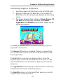
• ShowShifter provides you with various options to create an
ultimate home media center for your PC that you can use it
to record and playback TV, enjoy your entertainment over a
network, look at digital photos as a slide show on your TV
or PC monitor, and so on
• WinDVD creator Plus is a storyboard interface making
the entire DVD-making process as easy as moving pictures
around on your screen.
• WinDVD provides the automatic WinDVD software
installation.

6
Motherboard User’s Guide
Dimensions
• ATX form factor of 305 x 244 mm
Note: Hardware specifications and software items are
subject to change without notification.
Package Contents
Your motherboard package ships with the following items:
• The motherboard
• The User’s Guide
• One diskette drive ribbon cable (optional)
• One IDE drive ribbon cable
• The Software support CD
Optional Accessories
You can purchase the following optional accessories for this
motherboard.
• The Extended USB module
• The CNR v.90 56K Fax/Modem card
• The Serial ATA cable
Note: You can purchase your own optional accessories from the
third party, but please contact your local vendor on any issues
of the specification and compatibility.

7
Chapter 2: Motherboard Installation
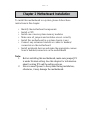
Chapter 2 Motherboard Installation
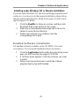
To install this motherboard in a system, please follow these
instructions in this chapter:
• Identify the motherboard components
• Install a CPU
• Install one or more system memory modules
• Make sure all jumpers and switches are set correctly
• Install this motherboard in a system chassis (case)
• Connect any extension brackets or cables to headers/
connectors on the motherboard
• Install peripheral devices and make the appropriate connec-
tions to headers/connectors on the motherboard
Note:
1. Before installing this motherboard, make sure jumper JP1
is under Normal setting. See this chapter for information
about locating JP1 and the setting options.
2. Never connect power to the system during installation;
otherwise, it may damage the motherboard.

8
Motherboard User’s Guide
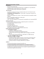
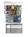
LABEL COMPONENTS
DIMM1--4 Four 184-pin DDR SDRAM sockets
IDE1/2 Primary/Secondary IDE connectors
ATX3 Standard 4-Pin ATX Power connector
ATX2 Standard 20-Pin ATX Power connector
USB2/3 Front Panel USB headers
FLOPPY Floppy Disk Drive connector
PANEL1 Front Panel Switch/LED header
SYSFAN System Fan connector
JP1 Clear CMOS jumper
JPX Performance Mode jumper
SPK1 Speaker header
Motherboard Components
SYSFAN
USB2/3PCI PANEL1SPK1
Socket-478
CPU
FAN
IR1
ATX2
FLOPPY
DDR
IDE
JP1
SATA
CNR1
AUDIO2
CD1
AGP1
ATX3
IO
PORTS
JPX
PWR/NBFAN

9
Chapter 2: Motherboard Installation
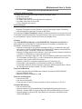
PS/2 Mouse
PS/2 Keyboard
Parallel Port (LPT1)
Serial Port COM1
LAN Port (optional)
USB Ports
Audio Ports
Use the upper PS/2 port to connect a PS/2
pointing device.
Use the lower PS/2 port to connect a PS/2
keyboard.
Use the Parallel port to connect printers or
other parallel communications devices.
Use the COM port to connect serial devices
such as mice or fax/modems. COM1 is
identified by the system as COM1.
Connect an RJ-45 jack to the LAN port to
connect your computer to the Network.
Use the USB ports to connect USB devices.
Use the three audio ports to connect audio
devices. The first jack is for stereo Line-In
signal. The second jack is for stereo Line-Out
signal. The third jack is for Microphone.
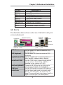
I/O Ports
The illustration below shows a side view of the built-in I/O ports
on the motherboard.
LABEL COMPONENTS
IR1 Infrared Port header
SATA1/2 Serial ATA connectors
PCI 1-5 32-bit PCI slots
CD1 Analog Audio Input header
AUDIO2 Front Panel Audio header
CPUFAN CPU Fan connector
PWR/NBFAN Power/NB Fan connector
CNR1 Communications Networking Riser slot
AGP1 Accelerated Graphics Port slot
Microphone
USB
ports
USB
ports
Serial Port
COM1
PS2
Keyboard
(Optional)
LAN port Line-In
Line-Out
Parallel Port (LPT1)
PS2 Mouse

10
Motherboard User’s Guide
Installing the Processor
This motherboard has a Socket 478 processor socket. When
choosing a processor, consider the performance requirements of
the system. Performance is based on the processor design, the
clock speed and system bus frequency of the processor, and the
quantity of internal cache memory and external cache memory.
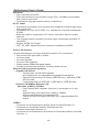
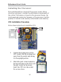
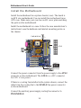
CPU Installation Procedure
Follow these instructions to install the CPU:
1 Unhook the locking lever of the
CPU socket. Pull the locking lever
away from the socket and raising
it to the upright position.
2 Match the pin1 corner marked as
the beveled edge on the CPU with
the pin1 corner on the socket.
Insert the CPU into the socket.
Do not use force.
Socket-478
pin1
1
CPUFAN

11
Chapter 2: Motherboard Installation
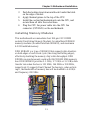
Installing Memory Modules
This motherboard accommodates four 184-pin 2.5V DIMM
sockets (Dual Inline Memory Module) for unbuffered DDR400
memory modules (Double Data Rate SDRAM), and maximum
4.0 GB installed memory.
DDR SDRAM is a type of SDRAM that supports data transfers
on both edges of each clock cycle (the rising and falling edges),
effectively doubling the memory chip’s data throughput. DDR
DIMMs can synchronously work with 266/333/400 MHz memory
bus. DDR SDRAM provides 2.1 GB/s, 2.7 GB/s or 3.2 GB/s data
transfer rate when the bus is 133 MHz, 166 MHz or 200 MHz,
respectively. It supports Dual Channel Technology; when activat-
ing it, the bandwidth of memory bus will be doubled to 6.4 GB/s
and frequency 200 MHz.
3 Push the locking lever down and hook it under the latch
on the edge of socket.
4 Apply thermal grease to the top of the CPU.
5 Install the cooling fan/heatsink unit onto the CPU, and
secure them all onto the socket base.
6 Plug the CPU fan power cable into the CPU fan
connector (CPUFAN) on the motherboard.
DIMM1--4

12
Motherboard User’s Guide
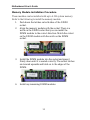
Memory Module Installation Procedure
These modules can be installed with up to 4 GB system memory.
Refer to the following to install the memory module.
1. Push down the latches on both sides of the DIMM
socket.
2. Align the memory module with the socket. There is a
notch on the DIMM socket that you can install the
DIMM module in the correct direction. Match the cutout
on the DIMM module with the notch on the DIMM
socket.
3. Install the DIMM module into the socket and press it
firmly down until it is seated correctly. The socket latches
are levered upwards and latch on to the edges of the
DIMM.
4. Install any remaining DIMM modules.

13
Chapter 2: Motherboard Installation
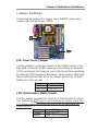
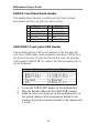
Jumper Settings
Connecting two pins with a jumper cap is SHORT; removing a
jumper cap from these pins, OPEN.
JPX: Performance Mode Jumper
Use this jumper to enable the function of Performance Accelera-
tion Technology. Please be noted enabling this jumper (Open Pins
1-2) perhaps comes with some risks that we do not guarrantee the
system stability.
JP1: Clear CMOS Jumper
Use this jumper to clear the contents of the CMOS memory. You
may need to clear the CMOS memory if the settings in the Setup
Utility are incorrect and prevent your motherboard from operating.
To clear the CMOS memory, disconnect all the power cables from
the motherboard and then move the jumper cap into the CLEAR
setting for a few seconds.
Function Jumper Setting
Normal Short Pins 1-2
Clear CMOS Short Pins 2-3
Function Jumper Setting
Disabled Short Pins 1-2
Enabled Open Pins 1-2 (Default)
JP1
1
JPX
1

14
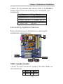
Motherboard User’s Guide
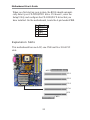
Connect the power connector from the power supply to the ATX2
connector on the motherboard. The ATX3 is a +12V connector
for CPU Vcore power.
If there is a cooling fan installed in the system chassis, connect the
cable from the cooling fan to the SYSFAN fan power connector
on the motherboard.
Connect the auxiliary power supply cooling fan connector to
PWR/NBFAN.
Install the Motherboard
Install the motherboard in a system chassis (case). The board is
an ATX size motherboard. You can install this motherboard in an
ATX case. Make sure your case has an I/O cover plate matching
the ports on this motherboard.
Install the motherboard in a case. Follow the case manufacturer’s
instructions to use the hardware and internal mounting points on
the chassis.
1
PWR/NBFAN
1
ATX3
SYSFAN
1
PANEL1
ATX2

15
Chapter 2: Motherboard Installation
Connecting Optional Devices
Refer to the following for information on connecting the
motherboard’s optional devices:
SPK1: Speaker Header
Connect the cable from the PC speaker to the SPK1 header on
the motherboard.
Pin Signal Pin Signal
1 HD_LED_P(+) 2 FP PWR/SLP(+)
3 HD_LED_N(-) 4 FP PWR/SLP(-)
5 RESET_SW_N(-) 6 POWER_SW_P(+)
7 RESET_SW_P(+) 8 POWER_SW_N(-)
9 RSVD_DNU 10 KEY
Pin Signal Pin Signal
1 SPKR 2 NC
3 GND 4 +5V
Connect the case switches and indicator LEDs to the PANEL1
header. Please refer to the following list of the PANEL1 pin
assignments.
1
IR1
USB3USB2
11
1
SPK1
AUDIO2
1

16
Motherboard User’s Guide
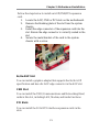
USB2/USB3: Front panel USB Header
The motherboard has USB ports installed on the rear edge I/O
port array. Additionally, some computer cases have USB ports at
the front of the case. If you have this kind of case, use auxiliary
USB headers USB2/USB3 to connect the front-mounted ports to
the motherboard.
1. Locate the USB2/USB3 header on the motherboard.
2. Plug the bracket cable onto the USB2/USB3 header.
3. Remove a slot cover from one of the expansion slots on
the system chassis. Install an extension bracket in the
opening. Secure the extension bracket to the chassis with
a screw.
AUDIO2: Front Panel Audio Header
This header allows the user to install auxiliary front-oriented
microphone and line-out ports for easier access.
Pin Signal Pin Signal
1 AUD_MIC 2 AUD_GND
3 AUD_MIC_BIAS 4 AUD_VCC
5 AUD_FPOUT_R 6 AUD_RET_R
7 HP_ON 8 KEY
9 AUD_FPOUT_L 10 AUD_RET_L
Pin Signal Pin Signal
1 VERG_FP_USBPWR0 2 VERG_FP_USBPWR0
3 USB_FP_P0(-) 4 USB_FP_P1(-)
5 USB_FP_P0(+) 6 USB_FP_P1(+)
7 GROUND 8 GROUND
9 KEY 10 USB_FP_OC0
Page is loading ...
Page is loading ...
Page is loading ...
Page is loading ...
Page is loading ...
Page is loading ...
Page is loading ...
Page is loading ...
Page is loading ...
Page is loading ...
Page is loading ...
Page is loading ...
Page is loading ...
Page is loading ...
Page is loading ...
Page is loading ...
Page is loading ...
Page is loading ...
Page is loading ...
Page is loading ...
Page is loading ...
Page is loading ...
Page is loading ...
Page is loading ...
Page is loading ...
Page is loading ...
-
 1
1
-
 2
2
-
 3
3
-
 4
4
-
 5
5
-
 6
6
-
 7
7
-
 8
8
-
 9
9
-
 10
10
-
 11
11
-
 12
12
-
 13
13
-
 14
14
-
 15
15
-
 16
16
-
 17
17
-
 18
18
-
 19
19
-
 20
20
-
 21
21
-
 22
22
-
 23
23
-
 24
24
-
 25
25
-
 26
26
-
 27
27
-
 28
28
-
 29
29
-
 30
30
-
 31
31
-
 32
32
-
 33
33
-
 34
34
-
 35
35
-
 36
36
-
 37
37
-
 38
38
-
 39
39
-
 40
40
-
 41
41
-
 42
42
-
 43
43
-
 44
44
-
 45
45
-
 46
46
-
 47
47
-
 48
48
-
 49
49
-
 50
50
-
 51
51
-
 52
52
-
 53
53
-
 54
54
-
 55
55
-
 56
56
-
 57
57
-
 58
58
-
 59
59
-
 60
60
-
 61
61
-
 62
62
-
 63
63
-
 64
64
-
 65
65
-
 66
66


Ask a question and I''ll find the answer in the document
Finding information in a document is now easier with AI
Related papers
Other documents
-
Canyon CNR-USBHUB5N Datasheet
-
Rosewill RHUB-210 User manual
-
M-Cab 7100096 Datasheet
-
Asus NX1001_V2 Datasheet
-
PC CHIPS M981G (V5.0A) User guide
-
-
-
-
-
M-Cab 7100064 Datasheet