Page is loading ...

Room Air Conditioner
SVC MANUAL(Exploded View)
CAUTION
Before Servicing the unit, read the safety precautions in General SVC manual.
Only for authorized service personnel.
Internal Use Only
http://biz.lgservice.com
MODEL : LS301HE
LS301CE

- 2 -
Copyright ©2009 LG Electronics. Inc. All right reserved.
Only for training and service purposes
LGE Internal Use Only
Air Conditioner Service Manual
TABLE OF CONTENTS
Safety Precautions..........................................................................................................................................3
Dimensions......................................................................................................................................................8
Symbols Used in this Manual.....................................................................................................................8
Indoor Unit..................................................................................................................................................8
Outdoor Unit...............................................................................................................................................9
Product Specifications .................................................................................................................................10
Installation .....................................................................................................................................................12
Piping Length and Elevation.....................................................................................................................12
How to Fix Installation Plate.....................................................................................................................13
Drill a Hole in the Wall ..............................................................................................................................13
Flaring work and connection of piping .......................................................................................................14
Flaring work..............................................................................................................................................14
Connection of piping-Indoor .....................................................................................................................15
Connection of the drain hose ...................................................................................................................20
Connection of piping-Outdoor ..................................................................................................................20
Connecting the cable between indoor unit and outdoor unit ...................................................................21
Connect the cable to the Indoor unit. .......................................................................................................21
Connect the cable to the outdoor unit ......................................................................................................22
Checking the drainage and forming the pipings........................................................................................23
Checking the drainage .............................................................................................................................23
Form the piping ........................................................................................................................................24
AIR PURGING ................................................................................................................................................25
Air purging................................................................................................................................................25
Test Running .................................................................................................................................................27
Operation .......................................................................................................................................................28
Operation .................................................................................................................................................28
Functions..................................................................................................................................................28
The function of main control.....................................................................................................................30
Display Function ......................................................................................................................................36
Self-diagnosis Function............................................................................................................................36
Name and Function-Remote Control (Cooling Models) ...........................................................................37
Name and Function-Remote Control (Heat Pump Models) ....................................................................38
Disassembly ..................................................................................................................................................39
Indoor Unit................................................................................................................................................39
Schematic Diagram.......................................................................................................................................43
Heat Pump/Cooling Only Series(Indoor Unit) ..........................................................................................43
Heat Pump Series (Outdoor Unit) ............................................................................................................44
INDOOR UNIT P.W.B. ASSEMBLY ..........................................................................................................45
OUTDOOR UNIT P.W.B. ASSEMBLY ......................................................................................................46
DISPLAY P.W.B. ASM ..............................................................................................................................47
Wiring Diagram.........................................................................................................................................48
Troubleshooting Guide .................................................................................................................................48
Refrigeration Cycle Diagram ....................................................................................................................50
Pipe length and the elevation ...................................................................................................................51
3-way Valve ..............................................................................................................................................52
Cycle Parts...............................................................................................................................................57
Electronic Parts ........................................................................................................................................58
Exploded View...............................................................................................................................................68

- 3 -
Copyright ©2009 LG Electronics. Inc. All right reserved.
Only for training and service purposes
LGE Internal Use Only
Safety Precautions
Safety Precautions
To prevent injury to the user or other people and property damage, the following instructions must
be followed.
■ Incorrect operation due to ignoring instruction will cause harm or damage. The seriousness is
classified by the following indications.
■ Meanings of symbols used in this manual are as shown below.
This symbol indicates the possibility of death or serious injury.
This symbol indicates the possibility of injury or damage to properties only.
Be sure not to do.
Be sure to follow the instruction.
Do not use damaged power cords, plugs, or a
loose socket.
Always use the power plug and socket with the
ground terminal.
• There is risk of fire of electric shock. • There is risk of electric shock.
Install the panel and the cover of control box
securely.
.Do not modify or extend the power cord.
• There is risk of fire of electric shock. • No grounding may cause electric shock.
■ Installation

- 4 -
Copyright ©2009 LG Electronics. Inc. All right reserved.
Only for training and service purposes
LGE Internal Use Only
Safety Precautions
Do not install the product on a defective instal-
lation stand.
Be sure the installation area does not
deteriorate with age.
• It may cause injury, accident, or damage to the
product.
• If the base collapses, the air conditioner could fall
with it, causing property damage, product failure,
and personal injury.
• Sharp edges could cause injury. Be especially care-
ful of the case edges and the fins on the condenser
and evaporator.
•
There is risk of fire, electric shock, explosion, or injury.
Be cautious when unpacking and installing the
product.
For installation, always contact the dealer or
an Authorized service center
For re-installation of the installed product,
always contact a dealer or an authorized ser-
vice center.
Do not install, remove, or re-install the unit by
yourself.
• There is risk of fire, electric shock, explosion, or
injury.
• There is risk of fire, electric shock, explosion, or
injury.

- 5 -
Copyright ©2009 LG Electronics. Inc. All right reserved.
Only for training and service purposes
LGE Internal Use Only
Safety Precautions
■ Operation
Do not turn the air-conditioner ON or OFF by
plugging or unplugging the power plug.
Use a dedicated outlet for this appliance.
• There is risk of fire or electrical shock. • There is risk of fire or electrical shock.
Grasp the plug to remove the cord from the
outlet. Do not touch it with wet hands.
Do not place a heater or other appliances near
the power cable.
• There is risk of fire or electrical shock. • There is risk of fire and electric shock.
Do not allow water to run into electrical parts. Do not store or use flammable gas or com-
bustibles near the air conditioner.
• There is risk of fire, failure of the product, or electric
shock.
• There is risk of fire or failure of product.
Wax
Thinner

- 6 -
Copyright ©2009 LG Electronics. Inc. All right reserved.
Only for training and service purposes
LGE Internal Use Only
Always check for gas (refrigerant) leakage after
installation or repair of product.
Install the drain hose to ensure that water is
drained away properly.
• Low refrigerant levels may cause failure of product. • A bad connection may cause water leakage.
Keep level even when installing the product. Use two or more people to lift and transport
the air conditioner.
• To avoid vibration or water leakage. • Avoid personal injury.
■ Installation
90˚
Unplug the unit if strange sounds, odors, or
smoke comes from it.
Be cautious that water could not enter the
product.
• There is risk of electric shock or fire. • There is risk of fire, electric shock, or product dam-
age.
Safety Precautions

- 7 -
Copyright ©2009 LG Electronics. Inc. All right reserved.
Only for training and service purposes
LGE Internal Use Only
Use a soft cloth to clean. Do not use harsh
detergents, solvents, etc.
Do not touch the metal parts of the product
when removing the air filter. They are very
sharp!
• There is risk of fire, electric shock, or damage to the
plastic parts of the product.
• There is risk of personal injury.
Do not step on or put anyting on the product.
(outdoor units)
Do not insert hands or other objects through
the air inlet or outlet while the air conditioner
is plugged in.
• There is risk of personal injury and failure of product. • There are sharp and moving parts that could cause
personal injury.
■ Operation
Wax
Safety Precautions

- 8 -
Copyright ©2009 LG Electronics. Inc. All right reserved.
Only for training and service purposes
LGE Internal Use Only
Dimensions
Dimensions
W
H
Tubing hole cover
Tubing hole cover
Installation plate
D
Indoor Unit
This symbol alerts you to the risk of electric shock.
This symbol alerts you to hazards that could cause harm to the
air conditioner.
This symbol indicates special notes.
NOTICE
Symbols Used in this Manual
W
mm(inch)
1,259(49.6)
H
mm(inch)
349(13.7)
D
mm(inch)
205(8.1)
Model
Dimension
30k SERIES

- 9 -
Copyright ©2009 LG Electronics. Inc. All right reserved.
Only for training and service purposes
LGE Internal Use Only
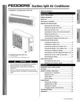
Dimensions
Outdoor Unit
MODEL
DIM
W
L7 L6 L8 L9
D
L1
L2
L3
L10L11
L4L5
H
Gas side
3-way valve
Liquid side
3-way valve
W mm(in ch) 870(34.3)
H mm(in ch) 800(31.5)
D mm(in ch) 320(12.6)
L1 mm(in ch) 370(14.6)
L2 mm(in ch) 340(13.4)
L3 mm(in ch) 25(1.0)
L4 mm(in ch) 775(30.5)
L5 mm(in ch) 25(1.0)
L6 mm(in ch) 546(21.5)
L7 mm(in ch) 162(6.4)
L8 mm(in ch) 162(6.4)
L9 mm(in ch) 54(2.1)
L10 mm(in ch) 74.5(2.9)
L11 mm(in ch) 79(3.1)
30k SERIES

- 10 -
Copyright ©2009 LG Electronics. Inc. All right reserved.
Only for training and service purposes
LGE Internal Use Only
Product Specifications
Product Specifications
Cooling Only
Items Unit LS301CE
Power Supply ø, V, Hz 230/208,60
Cooling Capacity BTU/h 28,000/27,000
Input W 3,600/3,450
Running Current A 16.0/16.5
COMP. Locked Rotor AMP. A 68
E.E.R BTU/hW 7.81/7.79
Air Circulation m
3
/min(cfm) 21(740)
Moisture Removal l/h(pts/hr) 3.7(7.8)
Noise Level Indoor, High dB(A) 49
(Sound Med dB(A) 46
Pressure, 1m) Low dB(A) 43
Outdoor, Max dB(A) 63
Features Temperature Control Thermistor
Air Deflection 4-way
Steps, Fan/Cool 3/3
Airflow Direction Control(up&down) Auto
Airflow Direction Control(left&right) Manual
Remocon Type Wireless LCD
Setting Temperature Range, Cooling Mode 64~86°F
Temperature Increment 2°F
Auto Operation(electronic control) Yes
Self Diagnosis Yes
Timer 24hr, On/Of
Sleep Operation Yes
Healthy Dehumidification Mode Yes
Restart Delay minutes 3
Refrigerant(R-22) Charge g(oz) 2550(89.9)
Power cord AWG #: P*mm
2
12:3*2.5
Fuse or breaker Capacity A 30A
Connecting Cable AWG #: P*mm
2
16:4*0.75
Connecting Tube Liquid Side mm(in) 6.35(1/4)
(ø. Socket Flare) Gas Side mm(in) 12.7(1/2)
Length, std m(ft) 7.62(25)
Additional Drain Hose(Outer Dia.) mm(in) 15.5(5/8)
Dimensions Indoor mm 1259*349*205
(WxHxD) in 49.6*13.7*8.1
Outdoor mm 870*800*320
in 34.3*31.5*12.6
Net Weight Indoor kg(lbs) 20
Outdoor kg(lbs) 71
* Design and Specifications subject to change without prior notice for product improvement.

- 11 -
Copyright ©2009 LG Electronics. Inc. All right reserved.
Only for training and service purposes
LGE Internal Use Only
Product Specifications
Cooling & Heating
Items Unit LS301HE
Power Supply ø, V, Hz 1,230/208,60
Cooling Capacity BTU/h 28,000/27,000
Heating Capacity BTU/h 29,000/28,000
Input Cooling W 3,600/3,450
Heating W 3,750/3,550
Running Current Cooling A 16.0/16.5
Heating A 16.5/17.0
COMP. Locked Cooling A 68
Rotor AMP. Heating A 68
E.E.R BTU/hW 7.78/7.82
C.O.P 2.26/2.30
Air Circulation m
3
/min(cfm) 21(740)
Moisture Removal l/h(pts/hr) 3.7(7.8)
Noise Level Indoor, High dB(A) 49
(Sound Med dB(A) 46
Pressure, 1m) Low dB(A) 43
Outdoor, Max dB(A) 63
Features Temperature Control Thermistor
Air Deflection 4-way
Steps, Fan/Cool/Heat 3/3/3
Airflow Direction Control(up&down) Auto
Airflow Direction Control(left&right) Manual
Remocon Type Wireless LCD
Setting Temperature Range, Cooling Mode
64~86°F
Heating Mode 60~86°F
Temperature Increment 2°F
Auto Operation(electronic control) Yes
Self Diagnosis Yes
Timer 24hr, On/Off
Sleep Operation Yes
Healthy Dehumidification Mode Yes
Restart Delay minutes 3
Defrost Control Yes
Hot Start Yes
Refrigerant(R-22) Charge g(oz) 2550(89.9)
Power cord AWG #: P*mm
2
12:3*2.5
Fuse or breaker Capacity A 30A
Connecting Cable AWG #: P*mm
2
18:4*0.75
Connecting Tube Liquid Side mm(in) 9.52(3/8)
(ø. Socket Flare) Gas Side mm(in) 15.88(5/8)
Length, std m(ft) 7.62(25)
Additional Drain Hose(Outer Dia.) mm(in) 15.5(5/8)
Dimensions Indoor mm 1259*349*205
(WxHxD) in 49.6*13.7*8.1
Outdoor mm 770*540*245 870*800*320
in 34.3*31.5*12.6
Net Weight Indoor kg(lbs) 20
Outdoor kg(lbs) 33(72.8) 71
* Design and Specifications subject to change without prior notice for product improvement.

- 12 -
Copyright ©2009 LG Electronics. Inc. All right reserved.
Only for training and service purposes
LGE Internal Use Only
Installation
Installation
Selection of the Best Location
Piping length and elevation
Installation Parts Provided
1. Indoor unit
■ Do not have any heat or steam near the unit.
■ Select a place where there are no obstacles in front
of the unit.
■ Make sure that condensation drainage can be con-
veniently routed away.
■ Do not install near a doorway.
■ Ensure that the space around the left and right of
the unit is more than 30cm(12"). The unit should be
installed as high on the wall as possible, allowing a
minimum of 12cm(4.8") from ceiling.
■ Use a stud finder to locate studs to prevent unnec-
essary damage to the wall.
2. Outdoor unit
■
If an awning is built over the unit to prevent direct sunlight or
rain exposure, make sure that heat radiation from the con-
denser is not restricted.
■
Ensure that the space around the back and sides is more than
10cm(4"). The front of the unit should have more than
70cm(28") of space.
■
Do not place animals and plants in the path of the warm air.
■
Take the air conditioner weight into account and select a place
where noise and vibration are minimum.
■
Select a place so that the warm air and noise from the air con-
ditioner do not disturb neighbors.
■ Rooftop Installations:
If the outdoor unit is installed on a roof structure, be
sure to level the unit. Ensure the roof structure and
anchoring method are adequate for the unit location.
Consult local codes regarding rooftop mounting.
If the outdoor unit is installed on root structures or walls,
this may result in excessive noise and vibration, and
maybe also classed as non serviceable installation.
More than
12cm(4.8")
More than
30cm(12")
More than
30cm(12")
More than 2.3m(7.5ft)
More than
10cm(4")
More than
10cm(4")
More than
60cm(24")
More than
60cm(24")
More than
70cm(28")
In case more than 5m(16.4ft)
Outdoor unit
Indoor unit
A
B
A
Oil trap
Outdoor unit
Indoor unit
B
Install the indoor unit on the wall where the height
from the floors more than 2.3meters(7.5ft).
A minimum pipe run of 7.5meters(25ft) is required to
minimise vibration & excessive noise.
CAUTION
30k 5/8" 3/8" 7.5(25) 15(50) 30(100)
30(1.102
)
Pipe Size
Capacity
(Btu/h)
GAS LIQUID
Max.
length
A m(ft)
Additional
Refrigerant
g/m(oz/ft)
Max.
Elevation
B m(ft)
Standard
Length
m(ft)
1. Type "A" screw
2. Installation Plate
3. Type "B" screw
4. Holder Remote Control

- 13 -
Copyright ©2009 LG Electronics. Inc. All right reserved.
Only for training and service purposes
LGE Internal Use Only
Installation
How to fix installation plate Drill a hole in the wall
The wall you select should be strong and solid enough to prevent
vibration
1. Mount the installation plate on the wall with four
type A screws. If mounting the unit on a concrete
wall, use anchor bolts.
Mount the installation plate horizontally by
aligning the centerline using a level.
2. Measure the wall and mark the centerline. It is also
important to use caution concerning the location
of the installation plate-routing of the wiring to
power outlets is through the walls typically.
Drilling the hole through the wall for piping con-
nections must be done safely.
5-7mm
(0.2~0.3")
Indoor
WALL
Outdoor
Installation Plate
Type "A" screw
(+1 D4.0 L38.0 MSR3/FZW)
30K
Right rear pipingLeft rear piping
50mm(2.0")
ø
70mm(2.76")180mm
(7.2")
115mm(4.5in)
■ Drill the piping hole with a ø70mm (0.76") hole
core drill. Drill the piping hole at either the right or
the left with the hole slightly slanted to the out-
door side.

- 14 -
Copyright ©2009 LG Electronics. Inc. All right reserved.
Only for training and service purposes
LGE Internal Use Only
Flaring work and connection of piping
Flaring work and connection of piping
Flaring work
Main cause for gas leakage is due to defect in flar-
ing work. Carry out correct flaring work in the follow-
ing procedure.
1. Cut the pipes and the cable.
■ Use the piping kit accessory or the pipes
purchased locally.
■ Measure the distance between the indoor and the
outdoor unit.
■ Cut the pipes a little longer than measured
distance.
■ Cut the cable 1.5m(59.1") longer than the pipe
length.
2. Burrs removal
■ Completely remove all burrs from the cut cross
section of pipe/tube.
■ Put the end of the copper tube/pipe in a down-
ward direction as you remove burrs in order to
avoid dropping burrs into the tubing.
3. Putting nut on
■ Remove flare nuts attached to indoor and outdoor
unit, then put them on pipe/tube having complet-
ed burr removal.
(not possible to put them on after flaring work)
Copper
pipe
90°
Slanted Uneven Rough
Bar
Copper pipe
Clamp handle
Red arrow mark
Cone
Yoke
Handle
Bar
"A"
Pipe
Reamer
Point down
4. Flaring work
■ Carry out flaring work using flaring tool as shown
below.
Firmly hold copper pipe in a die in the dimension
shown in the table above.
5. Check
■ Compare the flared work with figure below.
■ If flare is noted to be defective, cut off the flared
section and do flaring work again.
mm inch mm
ø6.35 1/4 0 ~ 0.5
ø9.52 3/8 0 ~ 0.5
ø12.7 1/2 0 ~ 0.5
ø15.88 5/8 0 ~ 1.0
Outside diameter A
Flare nut
Copper tube
Inclined
Inside is shiny without scratches
Smooth all round
Even length
all round
Surface
damaged
Cracked Uneven
thickness
= Improper flaring =

- 15 -
Copyright ©2009 LG Electronics. Inc. All right reserved.
Only for training and service purposes
LGE Internal Use Only
Flaring work and connection of piping
Connection of piping-Indoor
1. Remove the 2 screws of right side panel.
2. Remove the front right side panel by the arrow.
■ The connector can be disconnected by pulling it
while pressing the connector's hook.
■ Remove the 1 screw for fixing lower panel.
3. Remove the lower panel by the arrow.
■ Take care not to scratch the wall and mat to
drop.
1. Route the indoor tubing and the drain hose in the
direction of rear left.
2. Insert the connecting cable into the indoor unit
from the outdoor unit through the piping hole.
■ Do not connect the cable to the indoor unit.
■ Make a small loop with the cable for easy
connection later.
Right side panel
Drain hose
Main PCB
Lower panel
Lower panel
For left rear piping
CAUTION
When install, make sure that the
remaining parts must be
removed clearly so as not to
damage the piping and drain
hose, especially power cord and
connecting cable.

- 16 -
Copyright ©2009 LG Electronics. Inc. All right reserved.
Only for training and service purposes
LGE Internal Use Only
Flaring work and connection of piping
3. Tape the tubing, drain hose and the connecting
cable. Be sure that the drain hose is located at the
lowest side of the bundle. Locating at the upper side
can cause drain pan to overflow inside the unit.
3. Tape the tubing, drain hose and the connecting
cable. Be sure that the drain hose is located at the
lowest side of the bundle. Locating at the upper side
can cause drain pan to overflow inside the unit.
NOTE: If the drain hose is routed inside the room,
insulate the hose with an insulation material*
so that dripping from "sweating"(condensa-
tion) will not damage furniture or floors.
*Foamed polyethylene or equivalent is rec-
ommended.
4. Indoor unit installation
■ Hook the indoor unit onto the upper portion of the
installation plate.(Engage the three hooks of the
rear top and rear lower of the indoor unit with the
upper edge and lower edge of the installation
plate.) Ensure that the hooks are properly seated
on the installation plate by moving it left and right.
5. Connecting the pipings to the indoor unit and drain
hose to drain pipe.
■ Align the center of the pipings and sufficiently
tighten the flare nut by hand.
■ Tighten the flare nut with a wrench.
■ When extending the drain hose at the indoor unit,
install the drain pipe.
Connecting
cable
Loop
Gas side
piping
Liquid side
piping
Drain hose
Installation
plate
Three upper
hooks
Installation plate
Indoor unit
Three lower
hooks
Setting line
Indoor unit tubing Flare nut Pipings
Connection pipe
Flare nut
Indoor unit tubing
Torque wrench
Spanner (fixed)
Vinyl tape(narrow)
Adhesive
Drain pipe
Indoor unit drain hose
Pipe Size[Torque]
Capacity
(Btu/h)
Suction Evaporator
30K 5/8"[6.6kg.m] 3/8"[4.2kg.m]

- 17 -
Copyright ©2009 LG Electronics. Inc. All right reserved.
Only for training and service purposes
LGE Internal Use Only
Flaring work and connection of piping
6. Wrap the insulation material around the connecting
portion.
■
Overlap the connection pipe insulation material and
the indoor unit pipe insulation material. Bind them
together with vinyl tape so that there is no gap.
■ Wrap the area which accommodates the rear pip-
ing housing section with vinyl tape.
■ Bundle the piping and drain hose together by
wrapping them with vinyl tape over the range with-
in which they fit into the rear piping housing sec-
tion.
1. Route the indoor tubing and the drain hose to the
required piping hole position.
2. Insert the piping, drain hose and the connecting
cable into the piping hole.
3. Insert the connecting cable into the indoor unit.
■ Don't connect the cable to the indoor unit.
■ Make a small loop with the cable for easy
connection later.
4. Tape the drain hose and the connecting cable.
• Connecting cable
Plastic bands
Insulation material
Drain hose
Drain pipe
Connecting cable
Vinyl tape(narrow)
Connection
pipe
Connecting cable
Vinyl tape
(wide)
Wrap with vinyl tape
Indoor
unit pipe
Pipe
Wrap with vinyl tape
Drain hose
Pipe
Vinyl tape(wide)
For right rear piping

- 18 -
Copyright ©2009 LG Electronics. Inc. All right reserved.
Only for training and service purposes
LGE Internal Use Only
Flaring work and connection of piping
5. Indoor unit installation
■ Hook the indoor unit onto the upper portion of the
installation plate.(Engage the three hooks of the
rear top and rear lower of the indoor unit with the
upper edge and lower edge of the installation
plate.) Ensure that the hooks are properly seated
on the installation plate by moving it left and right.
6. Connecting the pipings to the indoor unit and the
drain hose to drain pipe.
■ Align the center of the pipings and sufficiently
tighten the flare nut by hand.
■ Tighten the flare nut with a wrench.
■ When extending the drain hose at the indoor unit,
install the drain pipe.
7. Wrap the insulation material around the connecting
portion.
■
Overlap the connection pipe heat insulation and the
indoor unit pipe heat insulation material. Bind them
together with vinyl tape so that there is no gap.
■ Wrap the area which accommodates the rear
piping housing section with vinyl tape.
Installation
plate
Three upper
hooks
Installation plate
Indoor unit
Three lower
hooks
Setting line
Vinyl tape
Adhesive
Drain hose
Indoor unit drain hose
(narrow)
Plastic bands
Insulation material
Vinyl tape(narrow)
Connection
pipe
Connecting cable
Indoor
unit piping
Pipe
Vinyl tape
(wide)
Wrap with vinyl tape
Indoor unit tubing Flare nut Pipings
Torque wrench
Indoor unit tubing
Spanner (fixed)
Connection pipe
Flare nut
Pipe Size[Torque]
Capacity
(Btu/h)
Suction Evaporator
30k 5/8"[6.6kg.m] 3/8"[4.2kg.m]

- 19 -
Copyright ©2009 LG Electronics. Inc. All right reserved.
Only for training and service purposes
LGE Internal Use Only
Flaring work and connection of piping
■ Bundle the piping and drain hose together by
wrapping them with cloth tape over the range
within which they fit into the rear piping housing
section.
8. Reroute the pipings and the drain hose across the
back of the chassis.
9. Reinstall the parts to the original position.
■ Refix the lower panel to the original position.
■ Connect display conductor.
■ Refix the front right side panel to the original
position with the two screws.
Drain hose
Vinyl tape(narrow)
Pipe
Wrap with
vinyl tape(wide)
Lower panel
Main PCB
Piping for
passage through
piping hole

- 20 -
Copyright ©2009 LG Electronics. Inc. All right reserved.
Only for training and service purposes
LGE Internal Use Only
Flaring work and connection of piping
■ The drain hose can be connected at two different
positions. Use the most convenient position and, if
necessary, exchange the position of the drain
pan, rubber cap and the drain hose.
➊ Drain pan
➋ Rubber cap
➌ Drain hose
➍ Exchange if necessary
■ Remove the drain hose.
■ Securely insert both the rubber plug and drain
hose into the drain outlets.
Be sure the rubber the cap is securely fastened
so that there is no leakage.
1. Align the center of the pipings and sufficiently
tighten the flare nut by hand.
2. Finally, tighten the flare nut with torque wrench
until the wrench clicks.
■ When tightening the flare nut with torque wrench,
ensure the direction for tightening follows the
arrow on the wrench.
1
2
3
4
Outdoor unit
Gas side piping
(Bigger diameter)
Liquid side
piping
(Smaller
diameter)
Torque wrench
Pipe Size[Torque]
Capacity
(Btu/h)
Suction Evaporator
30K 5/8"[6.6kg.m] 3/8"[4.2kg.m]
Connection of the drain hose Connection of piping-Outdoor
/