Zurn Z7440-XL Installation guide
- Category
- Sanitary ware
- Type
- Installation guide
This manual is also suitable for

*
Installation
Maintenance Instructions
Replacement Kits
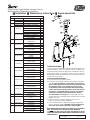
Z7440 Series Single Handle Lavatory Faucet
With Adjustable Temperature Limit Stop
SIERRA FAUCET PARTS
ITEM PART NO. DESCRIPTION QTY
1 RK7440-LH LEVER HANDLE 1
RK7440-LH-STN LEVER HANDLE, SATIN NICKEL 1
2 RK7440-LP LOOP HANDLE 1
RK7440-LP-STN LOOP HANDEL, SATIN NICKEL 1
RETAINING NUT ASSY.
RK7440-3 RETAINING NUT 1
RETAINING GASKET 1
3 ESCUTCHEON 1
RETAINING NUT ASSY.
RK7440-3-STN RETAINING NUT, SATIN NICKEL 1
RETAINING GASKET 1
ESCUTCHEON 1
4 RK7440-CART CARTRIDGE ASSEMBLY 1
W/ LIMIT STOP
AERATOR, STD 2.2 GPM
RK7440-94 AERATOR 1
WASHER 1
AERATOR, SATIN NICKEL 1
RK7440-94-STN STD. 2.2 GPM
AERATOR 1
WASHER 1
AERATOR SPRAY OUTLET
RK7440-94SO 1.0 GPM
AERATOR 1
WASHER 1
AERATOR, LAMINAR
FLOW, 2.2 GPM
7440-94LA AERATOR 1
WASHER 1
5 AERATOR, VANDAL
PROOF 2.2 GPM
7440-94VP/WK AERATOR 1
WASHER 1
KEY 1
AERATOR, VANDAL
PROOF 1.5 GPM
RK7440-94-VP1.5 AERATOR 1
WASHER 1
KEY 1
AERATOR, FLOW
CONTROL 0.5 GPM
7440-94FC/WK AERATOR 1
WASHER 1
KEY 1
6 RK7440-90 BASE PLATE 1
MOUNTING BRACKET
ASSY.
7 RK7440-17 BRACKET 2
HEX NUT 2
8 RK7440-HK INLET NUTS 2
SPOUT ASSY.
9 RK7440-36W SPOUT GASKET 1
WATERWAY SPOUT 1
AERATOR WASHER 1
Form # CF952 Date: 12/16/11 Product No.: IS7440
C.N. No. 128418 Rev. i Sheet 1 of 4
ANY SIERRA FAUCETS INSTALLED PRIOR TO 3-1-05 SHOULD
ADD - OS SUFFIX TO ALL REPAIR KIT PART NUMBERS
CAUTION: DO NOT APPLY SOLDER OR BRAZE TO INLET
TUBES. EXCESSIVE HEAT MAY DAMGE COMPONENTS OF THE
SIERRA FAUCET!
3. If faucet includes pop-up or grid drain, refer to next
page for pop-up assembly installation.
4. Connect left inlet tube to hot water supply and right inlet
tube to cold water supply.
CAUTION: Care should be taken
not to kink tubes when connecting to water supplies.
1. Shut off hot and cold water supplies.
2. Place faucet base plate on faucet and position on lavatory
sink. In some installations, a sealant may be required to
make a water tight seal between the faucet base plate and
the mounting surface. The installer should verify the
compatibility of the selected sealant with the mounting
surface manufacturer. Both plumber’s putty and silicone
sealants are compatible with Zurn faucets and fixtures.
Consult the mounting surface manufacture for their
recommendation of sealant. From underneath the sink,
position bracket on mounting studs and attach the hex nuts.
Tighten hex nuts.
INSTALLATION INSTRUCTIONS
CONGRATULATIONS
You have purchased a ZURN Quality Manufactured lavatory fau-
cet that contains a "life of the system" ceramic cartridge. The
Sierra faucet will provide you with years of trouble free service.
If you should have any questions, please contact your local
ZURN/TEMP-GARD representative or the factory at the address
on the back of this sheet.

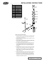
1. Remove the flange (2), then thread nut (5) and fiber gasket
(4) down as far as possible. Place the housing gasket (3)
on top of fiber gasket and nut.
2. Apply teflon tape to the threaded portion of tailpiece (7) and
thread into body (6).
3. Apply putty to the underside of the flange (2). Push the pop-
up assembly through the bottom of the lavatory sink. Screw
the flange (2) onto the pop-up body (6).
4. Face the pivot hole towards the wall. Pull down on the pop-
up assembly and tighten the nut (5), fiber gasket (4) and
housing gasket (3). Do not let the pop-up assembly turn
while tightening. Remove the excess plumbers putty from
the flange.
5. Place gasket (10) into nut (11). Place nut (11) over rod and
rod ball (9). Place seat (8) in rod ball hole. Tighten nut (11)
hand tight. The pop-up stopper (1) can be installed two
different ways: (A) removable and (B) non-removable. See
stopper drawing " A" and "B" on opposite page. Position
stopper into body (6).
6. Place clip (12) over a hole in the metal strap (13). Insert the
horizontal rod (9) through both the hole in the strap (13)
and clip (12). You can bend the strap for travel adjustment.
7. Place the lift rod (15) down through the hole in the faucet
and then the strap (13). Set the desired height of push rod
and tighten the thumb screw (14).
1
2
3
4
5
6
7
15
13
14
9
10
11
8
12
METAL POP-UP INSTALLATION
ITEM DESCRIPTION
1 STOPPER
2FLANGE
3 HOUSING GASKET
4 FIBER GASKET
5NUT
6BODY
7TAILPIECE
8SEAT
9ROD & BALL
10 GASKET
11 NUT
12 CLIP
13 STRAP
14 THUMB SCREW
15 LIFT ROD
METALLIC POP-UP
________________________
INSTALLATIONS INSTRUCTIONS
Form # CF952 Date: 12/16/11 Product No.: IS7440
C.N. No. 128418 Rev. i Sheet 2 of 4

(A) REMOVABLE STOPPER INSTALLATION
Install the complete pop-up assembly without the stopper.
Drop the stopper in the pop-up so that the bottom ledge of
the stopper rests on top of the pivot rod.
(B) NON-REMOVABLE STOPPER INSTALLATION
Before installing the pivot rod and strap assembly, insert the
stopper into the pop-up. Assemble pivot strap assembly to
pop-up body so that the rod goes through the lower opening
of the stopper.
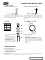
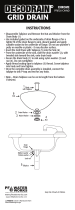
1. Apply putty underneath the flange
of body (1).
2. Apply teflon tape to the tailpiece
(5) and thread into body (1).
3. Place grid drain assembly down
through lavatory sink.
4. Install housing gasket (2), flat
gasket (3) and nut (4). Tighten nut.
5. Remove excess putty from flange (1).
1. Remove aerator and open valve to mixed position.
2. Turn water on for 1 minute.
3. Check for leaks under the sink.
4. Shut off faucet and replace aerator.
NOTE TO INSTALLER: When using vandal proof aerator (-VP) or flow control (-FC), keep the installation key fixed under sink or in
known location for future use. Keep installation instructions with faucet for future reference.
Faucet Test and Adjustment
Testing Procedures
Grid Drain
1
2
3
4
5
1. Remove handle.
2. Remove limit stop from cartridge.
3. Turn water on. Set to desired maximum temperature.
Clockwise rotation of stop increases temperature and
counterclockwise rotation of stop lowers temperature.
4. Re-install limit stop so that the lug on cartridge touches
lug on stop.
5. Re-install handle.
SETTING PROCEDURES
Temperature Limit Stop
ITEM DESCRIPTION
1BODY
2
HOUSING
GASKET
3
FLAT
HOUSING
GASKET
4 NUT
5TAILPIECE
GRID DRAIN ASSEMBLY
____________________________
INSTALLATION INSTRUCTIONS
Stopper Assembly
Form # CF952 Date: 12/16/11 Product No.: IS7440
C.N. No. 128418 Rev. i Sheet 3 of 4

Assuming proper care, your Zurn Sierra faucet will provide you with years of trouble free service. Care in cleaning is
important. The finish can be damaged with the use of harsh abrasive cleaners or polishes. To clean the valve, gently wipe
with damp cloth and blot dry with a soft towel.
Always use Zurn parts when performing routine maintenance. The use of non-Zurn parts will void your warranty. After any
maintenance is performed on the valve, flush the system as noted in the Faucet Test and Adjustment section of the
instructions.
Faucet leaks from under faucet handle. All supplies are on.
No water comes out of faucet spout. All supplies are on.
Water deflects at an angle from the faucetspout.
Faucet leaks from inlet supplies
Remove faucet handle. Tighten retaining cartridge nut. Do
not over tighten. Tighten until nut is snug.
Aerator is clogged. Remove aerator. Remove debris and
reinstall aerator.
Aerator has debris. Remove aerator. Remove debris and
reinstall aerator.
Aerator is loose. Water way may leak from aerator and ap-
pear under sink. Tighten aerator.
LIMITED WARRANTY: All goods sold hereunder are warranted to be free from defects in material and factory workmanship for a period
of three (3) years from the date of purchase. We will replace at no cost goods that prove defective provided we are notified in writing of
such defect and the goods are returned to Zurn Industries, Inc. prepaid at Falconer, New York, with evidence that they have been properly
maintained and used in accordance with instructions. We shall not be responsible for any labor charges or any loss, injury, or
damages whatsoever, including incidental or consequential damages. The sole and exclusive remedy shall be limited to the
replacement of the defective goods. Before installation and use, the purchaser shall determine the suitability of the product for his intended
use and the purchaser assumes all risk and liability whatever in connection therewith. Where permitted by law, the implied warranty of
merchantability is expressly excluded. If the products sold hereunder are "consumer products," the implied warranty of
merchantability is limited to a period of three (3) years and shall be limited solely to the replacement of the defective goods.
All weights stated in our catalogs and lists are approximate and are not guaranteed.
TEMP-GARD LIMITED WARRANTY
Problem
Solution
CLEANING INSTRUCTIONS
MAINTENANCE
___________________________________________
TROUBLE SHOOTING
Form # CF952 Date: 12/16/11 Product No.: IS7440
C.N. No. 128418 Rev. i Sheet 4 of 4
AquaSpec
®
is a registered trademark of Zurn Industries, LLC
©2011 Zurn Industries, LLC
ZURN INDUSTRIES, LLC.
♦♦
♦♦
♦
COMMERCIAL BRASS OPERATION
♦♦
♦♦
♦
5900 ELWIN BUCHANAN DRIVE
♦♦
♦♦
♦
SANFORD NC 27330
Phone: 1-800-997-3876
♦♦
♦♦
♦
Fax: 919-775-3541
♦♦
♦♦
♦
World Wide Web: www.zurn.com
In Canada: ZURN INDUSTRIES LIMITED
♦♦
♦♦
♦
3544 Nashua Drive
♦♦
♦♦
♦
Mississauga, Ontario L4V1L2
♦♦
♦♦
♦
Phone: 905-405-8272 Fax: 905-405-1292
-
 1
1
-
 2
2
-
 3
3
-
 4
4


Zurn Z7440-XL Installation guide
- Category
- Sanitary ware
- Type
- Installation guide
- This manual is also suitable for
Ask a question and I''ll find the answer in the document
Finding information in a document is now easier with AI
Related papers
-
Zurn Sierra Z7440-XL-CST Series Installation, Maintenance Instructions, Replacement Kits
-
Zurn Z842X1-XL-AF Installation guide
-
Zurn Z7872C-XL-SO Installation guide
-
-
-
Zurn P125-CC Installation guide
-
-
-
Zurn Z7300-SS-MT Installation guide
-
Zurn Z6913-XL-ACA-CP4 User guide
Other documents
-
Hikvision Digital Technology DS-1217ZJ Datasheet
-
Unbranded LSAZ087-040 Operating instructions
-
ANZZI KF-AZ127 Installation guide
-
-
-
 PF WaterWorks PF0725-BN-NO Installation guide
-
-
-
Design House 522052 Installation guide
-
American Standard Tendence 2088 User manual
