Whirlpool DHG65SG1CX User guide

Category
Hobs
Type
User guide
GB
COOKER
English,1
Contents
Installation, 2-6
Positioning and levelling
Electrical connection
Gas connection
Adapting to different types of gas
Technical data
Table of burner and nozzle specifications
Description of the appliance, 7
Overall view
Control panel
Start-up and use, 8-10
Using the hob
Using the oven
Oven cooking advice table
Precautions and tips, 11
General safety
Disposal
Respecting and conserving the environment
Care and maintenance, 12
Switching the appliance off
Cleaning the appliance
Replacing the oven light bulb
Gas tap maintenance
Assistance
Operating Instructions
GB
DHG65G1CX
Please phone us on
08448 24 24 24
to activate you
r
guarantee
2
GB
PLEASE PHONE US TO REGISTER YOUR APPLIANCE AND ACTIVATE YOUR PARTS GUARANTEE ON 08448 24 24 24
! Before operating your new appliance please read
this instruction booklet carefully. It contains
important information concerning the safe installation
and operation of the appliance.
! Please keep these operating instructions for future
reference. Make sure that the instructions are kept
with the appliance if it is sold, given away or moved.
! The appliance must be installed by a qualified
professional according to the instructions provided.
! Any necessary adjustment or maintenance must be
performed after the cooker has been disconnected
from the electricity supply.
Positioning
! This unit may be installed and used only in
permanently ventilated rooms according to the
British Standards Codes Of Practice: B.S. 6172/B.S.
5440, Par. 2 and B.S. 6891 Current Editions. The
following requirements must be observed:
a)The cooker should not be installed in a bed sitting
room with a volume of less than 20m
3
. If it is
installed in a room of volume less than 5m
3
an air
vent of effective area of 110cm
2
is required, if it is
installed in a room of volume between 5m
3
and
10m
3
a supplementary airvent area of 50cm2 is
required, if the volume exceeds 11m
3
no airvent is
required. However, if the room has a door or a
window which opens directly to the outside no air
vent is required even when the volume is between
5m
3
and 11m
3
.
b)During prolonged use of the appliance you may
consider it necessary to open a window to the
outside to improve ventilation.
c)If there are other fuel burning appliances in the
same room, B.S.5440 Part 2 Current Edition,
should, be consulted to determine the requisite air
vent requirements.
Levelling
If it is necessary to level the
appliance, screw the
adjustable feet into the places
provided on each corner of the
base of the cooker (see
figure).
Installation
The legs* fit into the slots on
the underside of the base of
the cooker.
Installation of the cooker
The appliance can be installed next to furniture units
which are no taller than the top of the cooker hob.
The wall in direct contact with the back panel of the
cooker must be made of non-flammable material.
During operation the back panel of the cooker could
reach a temperature of 50°C above room
temperature. For proper installation of the cooker,
the following precautions must be taken:
a)The appliance can be placed in a kitchen, dining
room or bedsit, but not in a bathroom.
b)All furniture around the appliance must be placed
at least 200 mm from the top of the cooker,
should the surface of the appliance be higher than
the worktop of this furniture. Curtains should not
be placed behind the cooker or less than 200 mm
away from the sides of the appliance.
c)Any hoods must be installed according to the
requirements in the installation manual for the
hoods themselves.
d)If the cooker is installed beneath a wall cabinet,
the latter must be situated at a minimum of 420
mm above the hob. The minimum distance
between the worktop and kitchen units made of
combustible material is 700 mm (Fig. A).
e)The wall in direct contact with the back panel of
the cooker must be made of non-flammable
materials.
f) The cooker is fitted with a safety chain that must
be attached to a hook, secured to the wall behind
the appliance.
! Some models can have their gas connection
inverted. It is important to make sure the safety
chain is always situated on the side which
corresponds to the hose holder (Fig. B).
Fig. A Fig. B
HOOD
420
Min.
min.
650
mm. with hood
min.
700
mm. without hood
mm.
600
Min. mm.
420
Min. mm.
GB
3
PLEASE PHONE US TO REGISTER YOUR APPLIANCE AND ACTIVATE YOUR PARTS GUARANTEE ON 08448 24 24 24
* Only available in certain models
Gas connection
T he cooker should be connected to the gas-supply
by a corgi registered installer. During installation of
this product it is essential to fit an approved gas tap
to isolate the supply from the appliance for the
convenience of any subsequent removal or
servicing. Connection of the appliance to the gas
mains or liquid gas must be carried out according to
the prescribed regulation in force, and only after it is
ascertained that it is adaptable to the type of gas to
be used. If not, follow the instructions indicated in
the paragraph headed “Adaptation to different gas
types”. On some models the gas supply can be
connected on the left or on the right, as necessary;
to change the
connection, reverse the
position of the hose
holder with that of the
cap and replace the
gasket (supplied with
the appliance). In the
case of connection to
liquid gas, by tank, use
pressure regulators that
conform to the
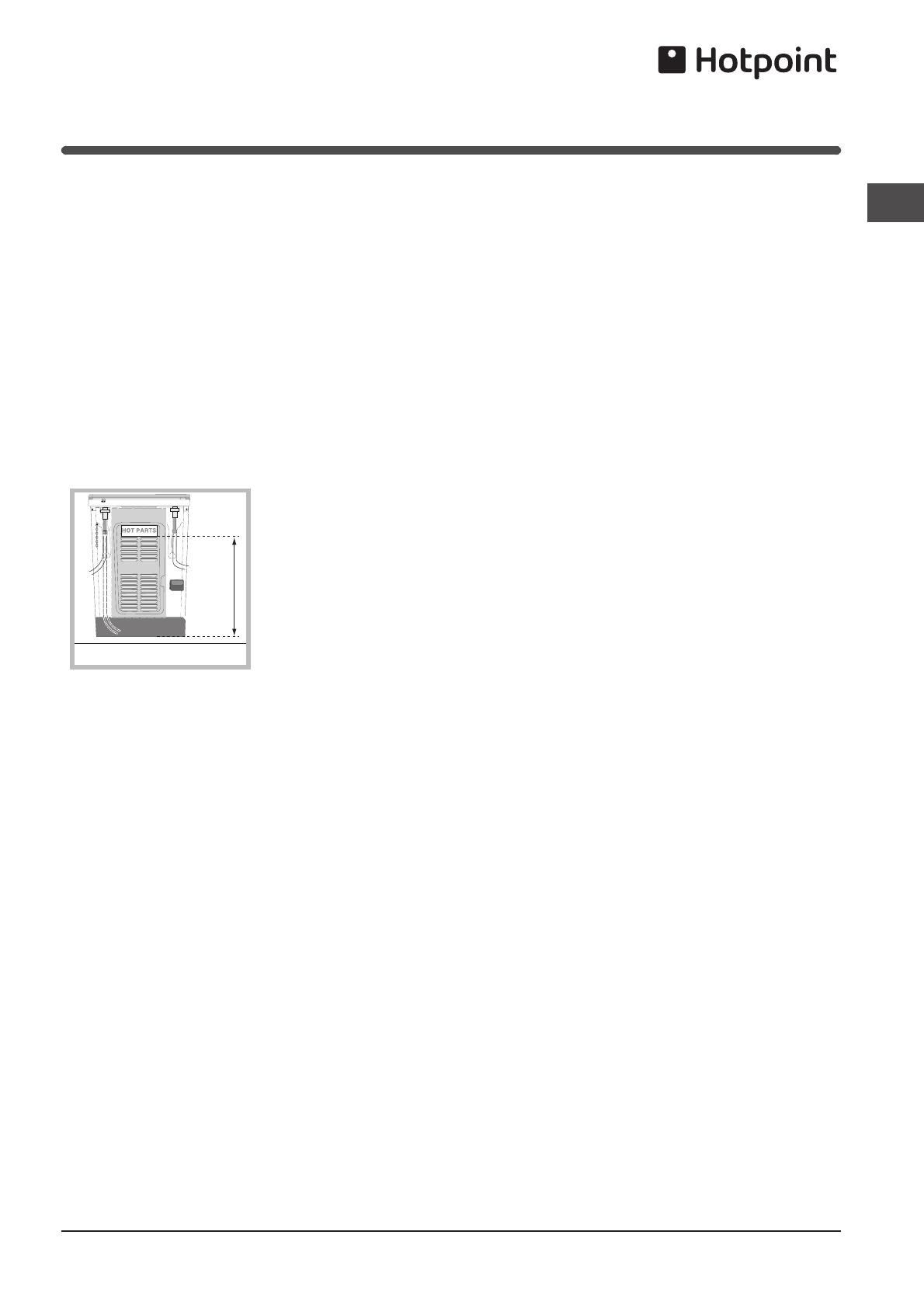
regulation in force. The gas supply must be
connected to the left of the appliance. Be sure that
the hose does not pass through the rear of the
cooker touching hot parts.
! Make sure the supply pressure conforms with the
values shown in the table entitled “Caracteristics of
the burners and nozzles”. When the cooker is
installed between cabinets (recessed), the
gas connection must be effected by an
approved flexible hose with bayonet fitting
(BS 669 Current Edition). The gas inlet for
the cookers is a threaded G 1/2 gas female
fitting.
Connecting the gas supply
To make the connection, a flexible hose should be
used corresponding to the current gas regulations
which are:
the hose must never be at any point in its lenght
in contact with the “hot” parts of the cooker;
the hose must never be longer than 1,5 metre;
the hose must not be subject to any tension or
torsional stress and it must not have any
excessively narrow curves or bottlenecks;
the hose must be easy to inspect along its entire
length to check its condition;
the hose must always be in good condition, never
attempt to repair.
! The installation must comply with gas safety
(installation and use) regulations 1984. In all cases
for the above, by low, a qualified, corgi approved
engineer must be called for installation.
Electrial connection
Power supply voltage and frequency: 230-240V a.c.
50/60 Hz.
! The supply cable must be positioned so that it
never reaches at any point a temperature 50°C
higher than the room temperature. The cable must
be routed away from the rear vents. Should you
require it, you may use a longer cable, however, you
must ensure that the cable supplied with the
appliance is replaced by one of the same
specifications in accordance with current standards
and legislation.
Your appliance is supplied with a 13 amp fused plug
that can be plugged into a 13 amp socket for
immediate use. Before using the appliance please
read the instructions below.
WARNING - THIS APPLIANCE MUST BE
EARTHED.
THE FOLLOWING OPERATIONS SHOULD BE
CARRIED OUT BY A QUALIFIED ELECTRICIAN.
Replacing the fuse:
When replacing a faulty fuse, a 13 amp ASTA
approved fuse to BS 1362 should always be used,
and the fuse cover re-fitted. If the fuse cover is lost,
the plug must not be used until a replacement is
obtained.
Replacement fuse covers:
If a replacement fuse cover is fitted, it must be of
the correct colour as indicated by the coloured
marking or the colour that is embossed in words on
the base of the plug. Replacements can be obtained
directly from your nearest Service Depot.
Removing the plug:
If your appliance has a non-rewireable moulded plug
and you should wish to remove it to add a cable
extension or to re-route the mains cable through
partitions, units etc., please ensure that either:
the plug is replaced by a fused 13 amp re-
wireable plug bearing the BSI mark of approval.
700 mm
HOT PARTS
4
GB
PLEASE PHONE US TO REGISTER YOUR APPLIANCE AND ACTIVATE YOUR PARTS GUARANTEE ON 08448 24 24 24
or:
the mains cable is wired directly into a 13 amp
cable outlet, controlled by a switch, (in
compliance with BS 5733) which is accessible
without moving the appliance.
! For appliances with a rating greater than 13 amp
(eg: electric hob, double ovens and freestanding
electric cookers etc.) the mains cable must be wired
into a cooker output point with a rating of 45 amp. In
this case the cable is not supplied.
Disposing of the plug:
Ensure that before disposing of the plug itself, you
make the pins unusable so that it cannot be
accidentally inserted into a socket. Instructions for
connecting cable to an alternative plug:
! The wires in the mains lead are coloured in
accordance with the following code:
Green & Yellow - Earth
Blue - Neutral
Brown - Live
If the colours of the wires in the mains lead do not
correspond with the coloured markings identifying
the terminals in your plug, proceed as follows:
Connect Green & Yellow wire to terminal marked “E
or or coloured Green or Green & Yellow.
Connect Brown wire to terminal marked “L” or
coloured Red.
Connect Blue wire to terminal marked “N” or
coloured Black.
If a 13 amp plug (BS 1363) is used it must be fitted
with a 13 amp fuse. A 15 amp plug must be
protected by a 15 amp fuse, either in the plug or
adaptor or at the distribution board. If you are in any
doubt about the electrical supply to your machine,
consult a qualified electrician before use.
How to connect an alternative plug:
The wires in this mains lead are coloured in
accordance with the following code:
BLUE NEUTRAL” (“N”)
BROWN LIVE” (“L”)
GREEN AND YELLOW EARTH” (“E”)
Disposing of the appliance
When disposing of the appliance please remove the
plug by cutting the mains cable as close as
possible to the plug body and dispose of it as
described above.
Checking the connection for leaks
When the installation process is complete, check
the hose fittings for leaks using a soapy solution.
Never use a flame.
Adapting to different types of gas
It is possible to adapt the appliance to a type of gas
other than the default type (this is indicated on the
rating label on the cover).
Adapting the hob
Replacing the nozzles for the hob burners:
1. Remove the hob grids and
slide the burners off their
seats.
2. Unscrew the nozzles using
a 7 mm socket spanner (see
figure), and replace them with
nozzles suited to the new type
of gas (see Burner and nozzle
specifications table).
3. Replace all the components by following the
above instructions in reverse.
Adjusting the hob burners’ minimum setting:
1. Turn the tap to the minimum position.
2. Remove the knob and adjust the regulatory
screw, which is positioned inside or next to the tap
pin, until the flame is small but steady.
! If the appliance is connected to a liquid gas
supply, the regulatory screw must be fastened as
tightly as possible.
3. While the burner is alight, quickly change the position
of the knob from minimum to maximum and vice versa
several times, checking that the flame is not
extinguished.
GREEN &
YELLOW
BROWN
BLUE
13 amp fuse
CROSS-BAR
CORD GRIP
GB
5
PLEASE PHONE US TO REGISTER YOUR APPLIANCE AND ACTIVATE YOUR PARTS GUARANTEE ON 08448 24 24 24
V
! The hob burners do not require primary air adjustment.
! After adjusting the appliance so it may be used
with a different type of gas, replace the old rating
label with a new one that corresponds to the new
type of gas (these labels are available from
Authorised Technical Assistance Centres).
! Should the gas pressure used be different (or vary
slightly) from the recommended pressure, a suitable
pressure regulator must be fitted to the inlet hose in
accordance with current national regulations relating
to “regulators for channelled gas”.
Adapting the oven
Replacing the oven burner nozzle
1.open the oven door fully
2.pull out the sliding oven
bottom
3.unscrew the burner fastening
screws
4.remove screw “V” and then
the oven burner.
5.Unscrew the oven burner
nozzle using the special
socket spanner for the
nozzles, or a 7 mm socket
spanner, and replace it with a
nozzle suited to the new type
of gas (see Table 1).
Take particular care
handling the spark plug
wires and the thermocouple
pipes.
6.Replace all the parts,
following the steps described
above in the reverse order..
Adjusting the gas oven burner’s minimum
setting:
1. Light the burner (see Start-up and Use).
2. Turn the knob to the minimum position (MIN) after
it has been in the maximum position (MAX) for
approximately 10 minutes.
3. Remove the knob.
4. Tighten or loosen the adjustment screws on the
outside of the thermostat pin (see figure) until the
flame is small but steady.
! If the appliance is connected to liquid gas, the
adjustment screw must be fastened as tightly as
possible.
5. Turn the knob from the MAX position to the MIN
position quickly or open and shut the oven door,
making sure that the burner is not extinguished.
Replacing the Triple ring burner nozzles
1. Remove the pan supports and lift the burners out of
their housing. The burner consists of two separate
parts (see pictures).
2. Unscrew the nozzles using a 7 mm socket spanner.
Replace the nozzles with models that are configured
for use with the new type of gas (see Table 1). The
two nozzles have the same hole diameter.
3. Replace all the components by completing the above
operations in reverse order.
Adjusting the burners’ primary air :
Does not require adjusting.
Setting the burners to minimum:
1. Turn the tap to the low flame position.
2. Remove the knob and adjust the adjustment screw,
which is positioned in or next to the tap pin, until the
flame is small but steady.
3. Having adjusted the flame to the required low setting,
while the burner is alight, quickly change the position
of the knob from minimum to maximum and vice
versa several times, checking that the flame does not
go out.
4. Some appliances have a safety device
(thermocouple) fitted. If the device fails to work when
the burners are set to the low flame setting, increase
this low flame setting using the adjusting screw.
5. Once the adjustment has been made, replace the
seals on the by-passes using sealing wax
! If the appliance is connected to liquid gas, the
regulation screw must be fastened as tightly as
possible.
! Once this procedure is finished, replace the old rating
sticker with one indicating the new type of gas used.
Stickers are available from any of our Service Centres.
! Should the gas pressure used be different (or vary
slightly) from the recommended pressure, a suitable
pressure regulator must be fitted to the inlet pipe (in
order to comply with current national regulations).
6
GB
PLEASE PHONE US TO REGISTER YOUR APPLIANCE AND ACTIVATE YOUR PARTS GUARANTEE ON 08448 24 24 24
Table of burner and nozzle specifications
Table 1 Liquid Gas Natural Gas
Burner D iam eter
(mm)
Thermal Power
kW (p.c.s.*)
By
Pass
1/100
Nozzle
1/100
Flow*
g/h
Nozzle
1/100
Flow*
l/h
Nominal Reduced
(
mm
)
(
mm
)
*** **
(
mm
)
Tripple
Crown
(
TC
)
130 3.25 1.50 63 2x65 236 232 2x99 309
Fast
(
Lar
g
e
)(
R
)
100 3.00 0.7 41 86 218 214 116 286
Se mi Fast
Medium
S
75 1.90 0.4 30 70 138 136 106 181
Au xili ar y
(
Small
)(
A
)
55 1.00 0.4 30 50 73 71 79 95
Oven
-
2.60 1.0 52 78 18
9
186 11
9
248
Supply
Pressures
Nominal (mbar)
Minimum (mbar)
Maximum
(
mbar
)
28-30
20
35
37
25
4
5
20
17
25
* At 15 °C 10 13 mbar-dry g as *** Butane P.C.S. = 49,47 MJ/Kg
** Propane P.C.S. = 50,37 MJ/Kg Natural P.C.S. = 37,78 MJ/m³
DHG65G1CX
S
R
TC A
TECHNICAL DATA
Oven Dimensions HxWxD 31x43,5x43,5 cm
Volume 58 l
Useful measurements
re la ti ng to t h e ove n
compartm ent
width 46 cm
depth 42 cm
height 8,5 cm
Voltage and frequency see data plate
Burner s may be adapted for use
with any type of gas
shown on the data plate
EC Directiv es 2006/95/ EC
dated 12/12/ 06 ( Low
Voltage) and subsequent
amendments - 04/108/EC
dated 15/12/ 04
(Electromagnetic
Compatibility) and
subsequent amendments
- 2009/142/EC dated
30/11/09 (Gas )
1275/2008(Stand-by/Off-
mode)
ENERGY LABEL and
ECODESIGN
Regulation (EU) No
65/2014 supplementing
Directive 2010/30/ EU.
Regulation (EU) No
66/2014 implementing
Directive 2009/125/E C.
Standard EN 15181\
Regulation (EU) No
66/2014 implementing
Directive 2009/125/E C.
Standard EN 30-2-1
ENERGY LABEL and
ECODESIGN
ENERGY LABEL and
ECODESIGN
GB
7
PLEASE PHONE US TO REGISTER YOUR APPLIANCE AND ACTIVATE YOUR PARTS GUARANTEE ON 08448 24 24 24
Description of the
appliance
*
Only available in certain models.
Control panel
Overall view
Hob grid
Control panel
GRILL rack
DRIPPING PAN
GUIDE RAILS
for the sliding racks
position 3
position 2
position 1
Gas burner
Containment
surface for spills
Adjustable foot
Adjustable foot
position 5
position 4
Glass Lid
5
15
30
45
GRILL pilot light
MINUTE MINDER
OVEN/GRILL control knob HOB BURNERS control knobs
8
GB
PLEASE PHONE US TO REGISTER YOUR APPLIANCE AND ACTIVATE YOUR PARTS GUARANTEE ON 08448 24 24 24
Using the hob
Lighting the burners
For each BURNER knob there is a complete ring
showing the strength of the flame for the relevant
burner.
To light one of the burners on the hob:
1. Bring a flame or gas lighter close to the burner.
2. Press the BURNER knob and turn it in an
anticlockwise direction so that it is pointing to the
maximum flame setting .
3. Adjust the intensity of the flame to the desired
level by turning the BURNER knob in an
anticlockwise direction. This may be the minimum
setting, the maximum setting or any position in
between the two.
If the appliance is fitted with an electronic lighting
device* (see figure), press the ignition button,
marked with the symbol
*
, then hold the BURNER
knob down and turn it in an anticlockwise direction,
towards the maximum flame setting, until the burner
is lit.The burner may be extinguished when the knob
is released. If this occurs, repeat the operation,
holding the knob down for a longer period of time.
! If the flame is accidentally extinguished, switch off
the burner and wait for at least 1 minute before
attempting to relight it.
If the appliance is equipped with a flame failure
safety device*, press and hold the BURNER knob for
approximately 3-7 seconds to keep the flame alight
and to activate the device.
To switch the burner off, turn the knob until it reaches
the stop position
•.
Start-up and use
Practical advice on using the burners
For the burners to work in the most efficient way
possible and to save on the amount of gas consumed,
it is recommended that only pans that have a lid and a
flat base are used. They should also be suited to the
size of the burner.
Burner ø Coo kware Diameter (cm)
Rapi d (R) 24 – 26
Triple Crown (TC) 24 26
Semi-rapid (S) 16 – 20
Auxiliary (A) 10 14
To identify the type of burner, please refer to the
diagrams contained in the “Burner and nozzle
specifications”.
! On the models supplied with a reducer shelf,
remember that this should be used only for the
auxiliary burner when you use casserole dishes with
a diameter under 12 cm.
Using the oven
! The first time you use your appliance, heat the
empty oven with its door closed at its maximum
temperature for at least half an hour. Ensure that the
room is well ventilated before switching the oven off
and opening the oven door. The appliance may emit a
slightly unpleasant odour caused by protective
substances used during the manufacturing process
burning away.
! Before operating the product,
remove all plastic film from the
sides of the appliance.
! Never put objects directly on
the bottom of the oven; this will
avoid the enamel coating being
damaged. Only use position 1
in the oven when cooking with the rotisserie spit.
Lighting the oven
To light the oven burner, bring a flame or gas lighter
close to opening F (see figure) and press the OVEN
control knob while turning it in an anticlockwise
direction until it reaches the MAX position.
If the appliance is fitted with an electronic lighting
device*, press the ignition button, marked with the
“*”symbol , then hold the OVEN control knob and turn
F
HOB GAS BURNER
SAFETY DEVICE
ELECTRONIC
LIGHTING DEVICE
WARNING! The glass lid can break in if
it is heated up. Turn off all the burners
and the electric plates before closing
the lid. *Applies to the models with
glass cover only.
GB
9
PLEASE PHONE US TO REGISTER YOUR APPLIANCE AND ACTIVATE YOUR PARTS GUARANTEE ON 08448 24 24 24
it in an anticlockwise direction, towards the MAX
position, until the burner is lit. If, after 15 seconds,
the burner is still not alight, release the knob, open
the oven door and wait for at least 1 minute before
trying to light it again. If there is no electricity the
burner may be lit using a flame or a lighter, as
described above.
! The oven is fitted with a safety device and it is
therefore necessary to hold the OVEN control knob
down for approximately 6 seconds.
! If the flame is accidentally extinguished, switch off
the burner and wait for at least 1 minute before
attempting to relight the oven.
Adjusting the temperature
To set the desired cooking temperature, turn the
OVEN control knob in an anticlockwise direction.
Temperatures are displayed on the control panel and
may vary between MIN (150°C) and MAX (250°C).
Once the set temperature has been reached, the oven
will keep it constant by using its thermostat.
Oven light
The light may be switched on at any moment by
turning the OVEN control knob.
Timer
To activate the Timer proceed as follows:
1. Turn the TIMER knob in a clockwise direction for
almost one complete revolution to set the buzzer.
2. Turn the TIMER knob in an anticlockwise direction
to set the desired length of time.
Grill
By turning the OVEN control knob in an
anticlockwise direction until it reaches the position:
, the infrared ray grill is activated. The grill
enables the surface of food to be browned evenly and
is particularly suitable for roast dishes, schnitzel and
sausages. Place the rack in position 4 or 5 and the
dripping pan in position 1 to collect fat and prevent
the formation of smoke.
! The GRILL indicator light shows when the grill is
operating.
! Always use the grill with the oven door shut; this
achieves better cooking results and saves energy
(approximately 10%).
Using the grill pan kit
The grill pan handle is detachable from the pan to
facilitate cleaning and storage. Fix the pan handle
securely before use:
1. Fit the handle to the grill pan so the external
‘hooks’ embrace the that edge of the pan (fig. 1)
2. Make sure that the middle part of the handle fits
exactly the protruding support of the pan (fig .2)
and holds the pan from the bottom.
The food must be placed on the rack in the grill pan.
Position the grill pan on top of the oven rack. The
best results are achieved by placing the oven rack on
the uppermost shelves. Pouring a little water into the
grill pan will make the collection of grease particles
more efficient and prevent the formation of smoke.
1
2
10
GB
PLEASE PHONE US TO REGISTER YOUR APPLIANCE AND ACTIVATE YOUR PARTS GUARANTEE ON 08448 24 24 24
Oven cooking advice table
Foods
Weight (in
kg)
Rack
position
Preheating time (min)
Recommended
Temperature (°C)
Cooking time
(minutes)
Pasta
Lasagne
Cannelloni
Gratin dishes
2.5
2.5
2.5
3
3
3
10
10
10
210
200
200
60-75
40-50
40-50
Meat
Veal
Chicken
Duck
Rabbit
Pork
Lamb
1.7
1.5
1.8
2
2.1
1.8
3
3
3
3
3
3
10
10
10
10
10
10
200
220
200
200
200
200
85-90
90-100
100-110
70-80
70-80
90-95
Fish
Mackerel
Dentex
Trout baked in foil
1.1
1.5
1
3
3
3
10
10
10
180-200
180-200
180-200
35-40
40-50
40-45
Pizza
Neapolitan-style
1
3
15
220
15-20
Pies
Biscuits
Tart
Savoury pies
Leavened cakes
0.5
1.1
1
1
3
3
3
3
15
15
15
15
180
180
180
180
30-35
30-35
45-50
35-40
Grilled foods
Veal steak
Cutlets
Hamburgers
Mackerel
Toast
1
1.5
1
1
4 pcs
4
4
3
4
4
5
5
5
5
5
15-20
20-30
20-30
15-20
2-4
GB
11
PLEASE PHONE US TO REGISTER YOUR APPLIANCE AND ACTIVATE YOUR PARTS GUARANTEE ON 08448 24 24 24
Precautions and tips
! This appliance has been designed and manufactured in
compliance with international safety standards.
The following warnings are provided for safety reasons and must
be read carefully.
General safety
The appliance was designed for domestic use inside the home
and is not intended for commercial or industrial use.
The appliance must not be installed outdoors, even in covered
areas. It is extremely dangerous to leave the appliance exposed
to rain and storms.
Do not touch the appliance with bare feet or with wet or damp
hands and feet.
The appliance must be used by adults only for
the preparation of food, in accordance with the
instructions outlined in this booklet. Any other
use of the appliance (e.g. for heating the room)
constitutes improper use and is dangerous.
The manufacturer may not be held liable for
any damage resulting from improper, incorrect
and unreasonable use of the appliance
The instruction booklet accompanies a class 1 (insulated) or
class 2 - subclass 1 (recessed between 2 cupboards)
appliance.
When the appliance is in use, the heating
elements and some parts of the oven door
become extremely hot. Make sure you don't
touch them and keep children well away.
Make sure that the power supply cables of other electrical
appliances do not come into contact with the hot parts of the
oven.
The openings used for the ventilation and dispersion of heat
must never be covered.
Always use oven gloves when placing cookware in the oven or
when removing it.
Do not use flammable liquids (alcohol, petrol, etc...) near the
appliance while it is in use.
Do not place flammable material in the lower storage
compartment or in the oven itself. If the appliance is switched
on accidentally, it could catch fire.
The internal surfaces of the compartment (where present) may
become hot.
Always make sure the knobs are in the
position and that the
gas tap is closed when the appliance is not in use.
When unplugging the appliance, always pull the plug from the mains
socket; do not pull on the cable.
Never perform any cleaning or maintenance work without
having disconnected the appliance from the electricity mains.
If the appliance breaks down, under no circumstances should you
attempt to repair the appliance yourself. Repairs carried out by
inexperienced persons may cause injury or further malfunctioning of
the appliance. Contact Assistance.
Do not rest heavy objects on the open oven door.
The appliance should not be operated by people (including
children) with reduced physical, sensory or mental capacities,
by inexperienced individuals or by anyone who is not familiar
with the product. These individuals should, at the very least,
be supervised by someone who assumes responsibility for their
safety or receive preliminary instructions relating to the
operation of the appliance.
Do not let children play with the appliance.
If the cooker is placed on a pedestal, take the
necessary precautions to prevent the cooker from
sliding off the pedestal itself.
Disposal
When disposing of packaging material: observe local legislation so
that the packaging may be reused.
The European Directive 2002/96/EC on Waste Electrical and
Electronic Equipment (WEEE), requires that old household
electrical appliances must not be disposed of in the normal
unsorted municipal waste stream. Old appliances must be
collected separately in order to optimise the recovery and
recycling of the materials they contain and reduce the impact
on human health and the environment. The crossed out
“wheeled bin” symbol on the product reminds you of your
obligation, that when you dispose of the appliance it must be
separately collected.
Consumers should contact their local authority or retailer for
information concerning the correct disposal of their old
appliance.
12
GB
PLEASE PHONE US TO REGISTER YOUR APPLIANCE AND ACTIVATE YOUR PARTS GUARANTEE ON 08448 24 24 24
Switching the appliance off
Disconnect your appliance from the electricity supply
before carrying out any work on it.
Cleaning the appliance
! Never use steam cleaners or pressure cleaners on
the appliance.
The stainless steel or enamel-coated external parts
and the rubber seals may be cleaned using a
sponge that has been soaked in lukewarm water
and neutral soap. Use specialised products for the
removal of stubborn stains. After cleaning, rinse
well and dry thoroughly. Do not use abrasive
powders or corrosive substances.
The hob grids, burner caps, flame spreader rings
and burners may be removed to make cleaning
easier; wash them in hot water and non-abrasive
detergent, making sure all burnt-on residue is
removed before drying them thoroughly.
Clean the terminal part of the flame failure safety
devices* frequently.
The inside of the oven should ideally be cleaned
after each use, while it is still lukewarm. Use hot
water and detergent, then rinse well and dry with a
soft cloth. Do not use abrasive products.
Clean the glass part of the oven door using a
sponge and a non-abrasive cleaning product, then
dry thoroughly with a soft cloth. Do not use rough
abrasive material or sharp metal scrapers as these
could scratch the surface and cause the glass to
crack.
The accessories can be washed like everyday
crockery, and are even dishwasher safe.
Do not close the cover when the burners are alight
or when they are still hot.
Inspecting the oven seals
Check the door seals around the oven regularly. If the
seals are damaged, please contact your nearest
Authorised After-sales Service Centre. We recommend
that the oven is not used until the seals have been
replaced.
Replacing the oven light bulb
1. After disconnecting the oven
from the electricity mains,
remove the glass lid covering
the lamp socket (see figure).
2. Remove the light bulb and
replace it with a similar one:
voltage 230 V, wattage 25 W,
cap E 14.
3. Replace the lid and reconnect the oven to the
electricity supply.
Gas tap maintenance
Over time, the taps may become jammed or difficult to
turn. If this happens, the tap must be replaced.
! This procedure must be performed by a qualified
technician authorised by the manufacturer.
Assistance
! Never use the services of an unauthorised
technician.
Please have the following information to hand:
The type of problem encountered.
The appliance model (Mod.).
The serial number (S/N).
The latter two pieces of information can be found on
the data plate located on the appliance.
Care and maintenance
The cover
If the cooker is fitted with
a glass cover, this cover
should be cleaned using
lukewarm water. Do not
use abrasive products.
It is possible to remove
the cover in order to
make cleaning the area
behind the hob easier.
Open the cover fully and pull it upwards (
see figure
).
! Do not close the cover when the burners are alight
or when they are still hot.
GB
13
PLEASE PHONE US TO REGISTER YOUR APPLIANCE AND ACTIVATE YOUR PARTS GUARANTEE ON 08448 24 24 24
Respecting and conserving the
environment
• Whenever possible, avoid pre-heating the oven
and always try to fill it. Open the oven door as little
as possible because heat is lost every time it is
opened. To save a substantial amount of energy,
simply switch off the oven 5 to 10 minutes before
the end of your planned cooking time and use the
heat the oven continues to generate.
Automatic programmes are based on standard
food product.
• Keep gaskets clean and tidy to prevent any door
energy losses
• If you have a timed tariff electricity contract, the
“delay cooking” option will make it easier to save
money by moving operation to cheaper time
periods.
• The base of your pot or pan should cover the hot
plate. If it is smaller, precious energy will be
wasted and pots that boil over leave encrusted
remains that can be difficult to remove.
• Cook your food in closed pots or pans with well-
fitting lids and use as little water as possible.
Cooking with the lid off will greatly increase energy
consumption
• Use purely flat pots and pans
• If you are cooking something that takes a long
time, it’s worth using a pressure cooker, which is
twice as fast and saves a third of the energy.
'Stay Clean' Panel
'Stay Clean' panels are covered with a special enamel
which absorbs cooking soils. At higher temperatures
the soiling is slowly destroyed. In most cases normal
cooking at higher temperatures will permit this cleaning
to take place automatically. However, if higher cooking
temperatures are not used regularly then it may be
necessary, in order to prevent heavy soiling, to run the
oven at maximum temperature for at least two hours,
from time to time. The 'Stay Clean' panel can be
washed in warm soapy water followed by rinsing in clear
water. Dry well with a soft cloth.
NOTE: Do not use enzyme washing powder,
harsh abrasives or chemical oven cleaners
of any kind.
14
GB
PLEASE PHONE US TO REGISTER YOUR APPLIANCE AND ACTIVATE YOUR PARTS GUARANTEE ON 08448 24 24 24
After Sales Service
No one is better placed to care for your Hotpoint appliance during the course of its working life
than us - the manufacturer.
Essential Contact Information
Hotpoint Service
We are the largest service team in the country offering you access to 400 skilled telephone
advisors and 1100 fully qualified engineers on call to ensure you receive fast, reliable, local
service.
UK: 08448 224 224
Republic of Ireland: 0818 313 413
www.hotpoint.co.uk
Please note: Our advisors will require the following information:
Model number
Serial number
Parts & Accessories
We supply a full range of genuine replacement parts as well as accessory products that protect
and hygienically clean your appliance to keep it looking good and functioning efficiently
throughout its life.
UK: 08448 225 225
Republic of Ireland: 0818 313 413
www.hotpointservice.co.uk
Appliance Registration
We want to give you additional benefits of Hotpoint ownership. To activate your FREE 5 year
parts guarantee you must register your appliance with us.
UK 08448 24 24 24
Republic of Ireland: 01 230 0800
www.hotpointservice.co.uk
As part of Hotpoint's continued commitment to helping the environment, Hotpoint reserves the
right to use quality, recycled components to keep down customer costs and minimise material
wastage.
Indesit Company UK Limited, Morley Way, Peterborough, PE2 9JB
Indesit Company, Unit 49 Airways Industrial Estate, Dublin 17
GB
15
PLEASE PHONE US TO REGISTER YOUR APPLIANCE AND ACTIVATE YOUR PARTS GUARANTEE ON 08448 24 24 24
Guarantee
12 months Parts and Labour Guarantee
Your appliance has the benefit of our manufacturer's guarantee, which covers the cost of
breakdown repairs for twelve months from the date of purchase.
This gives you the reassurance that if, within that time, your appliance is proven to be defective
because of either workmanship or materials, we will, at our discretion, either repair or replace the
appliance at no cost to you.
The guarantee is subject to the following conditions:
- The appliance has been installed and operated correctly and in accordance with our operating
and maintenance instructions.
- The appliance is only used on the electricity or gas supply printed on the rating plate.
- The appliance has been used for normal domestic purposes only.
- The appliance has not been altered, serviced, maintained, dismantled or otherwise interfered
with by any person not authorised by us.
- Any repair work must be undertaken by us or our appointed agent.
- Any parts removed during repair work or any appliance that is replaced become our property.
- The appliance is used in the United Kingdom or Republic of Ireland.
The guarantee does not cover:
- Damage resulting from transportation, improper use, neglect or interference or as a result of
improper installation.
- Replacement of any consumable item or accessory. These include but are not limited to: plugs,
cables, batteries, light bulbs, fluorescent tubes and starters, covers and filters.
- Replacement of any removable parts made of glass or plastic.
THE GUARANTEE WILL NOT APPLY IF THE APPLIANCE HAS BEEN USED IN
COMMERCIAL OR NON-DOMESTIC PREMISES.
5 Year Parts Guarantee
Hotpoint also offers you a FREE 5 year parts guarantee. This additional guarantee is conditional on
you registering your appliance with us and the parts being fitted by one of our authorised engineers.
There will be a charge for our engineer's time. To activate the extra parts warranty on your appliance,
simply call our registration line on 08448 24 24 24 (ROI 01 230 0800)
Extended Guarantees
We offer a selection of protection plans that enable you to fully cover yourself against the expense of
repair bills for the life of your policy. To find the ideal plan for you please call our advice line on 08448
226 226 (ROI 01 230 0233)
Free Helpdesk Service
We have a dedicated team who can provide free advice and assistance with your appliance if you
experience any technical difficulties within the first 90 days of ownership.
Simply call our Hotpoint Service Hotline on 08448 224 224 (ROI 0818 313 413) for
telephone assistance, or, where necessary, to arrange for an engineer to call.
16
GB
PLEASE PHONE US TO REGISTER YOUR APPLIANCE AND ACTIVATE YOUR PARTS GUARANTEE ON 08448 24 24 24
04/2014- 195123122.00
XEROX FABRIANO
Indesit Company S.P.A.
Viale Aristide Merloni,47
60044 Fabriano (AN)
www.hotpoint.co.uk
! ATTENTION
DURING INSTALLATION
THE FEET OF THE APPLIANCE
MUST BE LOWERED SO THAT
AN AIR GAP OF AT LEAST
10MM (1CM) IS LEFT BETWEEN
THE BASE OF THE APPLIANCE
AND THE FLOOR.
! VERY HOT SURFACES
YOU MUST KEEP THE OVEN
AND GRILL CAVITIES CLEAN
FOOD OR GREASE ON THESE
SURFACES COULD CAUSE
SMOKE AND POSSIBLY EVEN BURN
! ATTENTION
WHEN USING THE MAIN OVEN
YOU MUST ENSURE THAT THE
BASE OF THE CAVITY IS NOT
COVERED WITH ALUMINUM
FOIL, UTENSIL OR ANY OTHER
FORM OF COVERING. FAILURE
TO DO THIS MAY RESULT IN
THE CAVITY BEING DAMAGED.
10 mm
! ATTENTION! ATTENTION
! ATTENTION ! ATTENTION
! VERY HOT SURFACES! VERY HOT SURFACES
  • Page 1 1
  • Page 2 2
  • Page 3 3
  • Page 4 4
  • Page 5 5
  • Page 6 6
  • Page 7 7
  • Page 8 8
  • Page 9 9
  • Page 10 10
  • Page 11 11
  • Page 12 12
  • Page 13 13
  • Page 14 14
  • Page 15 15
  • Page 16 16

Whirlpool DHG65SG1CX User guide

Category
Hobs
Type
User guide

Ask a question and I''ll find the answer in the document

Finding information in a document is now easier with AI