Page is loading ...

ADVANCED ENGINE MANAGEMENT INC.
2205 126
th
Street Unit A, Hawthorne, CA. 90250
Phone: (310) 484-2322 Fax: (310) 484-0152
http://www.aempower.com
Instruction Part Number: 10-1910 Rev 080710
2007 Advanced Engine Management, Inc.
Page 1
Installation Instructions for
30-1930
Fuel Ignition Controller (F/IC)
This product is legal in California for racing vehicles only and should
never be used on public highways.
WARNING:
!
This installation is not for the electrically or mechanically
challenged! Use the F/IC with EXTREME caution! If you are
uncomfortable with anything about this, please refer the
installation to an AEM trained tuning shop or call 800-423-0046
for technical assistance. You should also visit the AEM
Performance Electronics Forum at http://www.aempower.com
NOTE: AEM holds no responsibility for any engine damage that
results from the misuse of this product!
Download the latest AEM software at:
http://www.aemelectronics.com/downloads

Page 2
Thank you for purchasing the AEM F/IC. Inside the box you will find the F/IC
module, a universal wiring harness, a software CD, and other components needed to
install the F/IC and adjust the FIC via a laptop or PC. See Figure 1. For more
information on select vehicles, please visit the FIC section of the AEM Electronics
Forum. The forum can be accessed from the AEM homepage (www.aempower.com),
by clicking on the link titled “Forums”.
Getting started
(Note: The following is a universal wiring installation. For more specific
information on some of the more common vehicles, please visit the FIC section of the
AEM Electronics Forum. Also, to make the install easier and to save you from cutting
your factory harness, we recommend the use of a “patch” or “extension” harness.
These harnesses are readily available from companies like Boomslang
(http://www.boomslang.us/) or Auto Sport Wiring (http://www.autosportwiring.com/).)
The first step in connecting the F/IC is to determine what features/functions are needed
and which functions are not needed. The F/IC comes with a universal flying lead that
has 66 non-terminated wires. At first glance, the bundle of wires is quite intimidating.
However, by answering some questions about your vehicle and what you want to do
with the F/IC, some of the wires can be eliminated. Before we begin, we must learn the
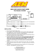
two types of connections used with the F/IC: the tap and the intercept. See Figure 2.
Figure 1. Kit Contents
Kit Contents:
* F/IC Module
* Flying Lead Harness
* Bypass plug
* Instructions
* USB Cable
* Vacuum Hose (3 Ft)
* Tee Fitting
* Zip Tie (3)

Page 3
TO ECUTO ENGINE
TO FIC
CUT WIRE
TO ENGINE
TO FIC
TO ECU
WIRE CONNECTIONS
INTERCEPT TAP
Does your vehicle have a Mag/VR or Hall style Crank Sensor?
Magnetic(Mag) or Variable Reluctance(VR) style sensors typically have two
wires. Hall style sensors typically have three wires. Vehicles have either a Mag/VR or
a Hall style Crank Sensor, not both. If your vehicle has a Mag/VR sensor, the two Hall
sensor wires can be eliminated. If your vehicle has a Hall sensor the four Mag sensor
wires can be eliminated. Connect the Crank Sensor as shown below in Figure 3.
SENSOR
ECU
FIC
VREF
CRK HALI +
CRK HALO +
HALL STYLE CRANK CONNECTION
GND
SIGNAL
SENSOR
ECU
FIC
-
CRK MAGI +
CRK MAGO +
MAG STYLE CRANK CONNECTION
+
CRK MAGI -
CRK MAGO -
Does your vehicle have one or two Cam Sensor(s)?
If your vehicle has one Cam Sensor, the two “Cam 2” Hall wires and four “Cam 2”
Mag wires can be eliminated.
Does your vehicle have a Mag or Hall style Cam Sensor?
As with the Crank Sensor, a vehicle will have one or the other, not both. Either
the “Cam 1” Hall or the Cam 1 Mag wires can be eliminated. Connect to Cam Sensor
as shown below in Figure 4.
Figure 2. Wire Connections
Figure 3. Crank Sensor Connection

Page 4
SENSOR
ECU
FIC
VREF
CAM1 HALI +
CAM1 HALO +
HALL STYLE CAM 1 CONNECTION
GND
SIGNAL
SENSOR
ECU
FIC
-
CAM1 MAGI +
CAM1 MAGO +
MAG STYLE CAM 1 CONNECTION
+
CAM1 MAGI -
CAM1 MAGO -
If your vehicle has two Cam Sensors, connect the “Cam 2” sensor as shown below in
Figure 5.
SENSOR
ECU
FIC
VREF
CAM2 HALI +
CAM2 HALO +
HALL STYLE CAM 2 CONNECTION
GND
SIGNAL
SENSOR
ECU
FIC
-
CAM2 MAGI +
CAM2 MAGO +
MAG STYLE CAM 2 CONNECTION
+
CAM2 MAGI -
CAM2 MAGO -
Figure 4. Cam 1 Connection
Figure 5. Cam 2 Connection

Page 5
Do you want to modify or clamp the MAF Sensor voltage?
If not, the two MAF Sensor wires can be eliminated. If so, connect the MAF
Sensor as shown below in Figure 6.
SENSOR
ECU
FIC
VREF
MAF IN +
MAF OUT +
MAF CONNECTION
GND
SIGNAL (+)
Does your vehicle have both a MAP Sensor and a MAF Sensor? or Do you want to
remap another analog signal on your car?
If so, connect the “Analog A/B” wires as shown below in Figure 7. If not, remove
the unused wires for “Analog A/B”.
SENSOR
ECU
FIC
VREF
ANALOG A/B IN +
ANALOG A/B CONNECTION
GND
SIGNAL (+)
ANALOG A/B OUT +
How many Injectors do you want to control with the F/IC?
The F/IC has 8 Injector drivers. There are two wires per driver. The wires for the
unused drivers can be eliminated.
Do you want to control the primary Injectors on the engine, or control additional
secondary Injectors?
Connect the injectors as shown below in Figure 8.
FUEL
INJECTOR 1
ECU
FIC
FUEL INJ 1
TO +12V
INJ 1 OUT
INJ 1 IN
PRIMARY FUEL INJECTOR CONNECTION
Figure 6. MAF Sensor Connection
Figure 7. Analog A/B Connection

Page 6
PRIMARY FUEL
INJECTOR 1
ECU
FIC
FUEL INJ 1
TO +12V
INJ 1 OUT
INJ 1 IN
SECONDARY FUEL INJECTOR CONNECTION
SECONDARY
FUEL INJECTOR 1
TO +12V
Do you want to modify the Oxygen(O2)/UEGO sensor signals?
If not, the “O2” sensor wires can be eliminated. If so, connect the sensors as
shown below in Figure 9.
.
SENSOR
ECU
FIC
SIGNAL
HEATER
O21 +
NARROW BAND O2 SENSOR CONNECTION
SEE RESISTOR DETAIL
TO FACTORY HARNESS
SIGNAL GND
POWER
Figure 8. Fuel Injector Connection
TO NARROW BAND O2 SENSOR
RESISTOR DETAIL
TO NARROW BAND O2 SENSOR
TO ECU
TO ECU
WRAP BARE WIRES
AROUND RESISTOR LEADS
RESISTOR
SOLDER
SOLDER
APPLY SHRINK TUBING
AFTER SOLDERING
TO FIC
TAP CONNECTION MUST BE
ON ECU SIDE OF RES ISTOR

Page 7
SENSOR
ECU
FIC
NERNST CELL
O21 +
WIDE BAND O2 SENSOR CONNECTION
TO FACTORY HARNESS
POWER
Connect the F/IC power wire. See Figure 10.
ECU
FIC
SW +12V
TO SWITCHED +12V
IGN PWR
SWITCHED +12 VDC CONNECTION
Connect the TPS signal to the F/IC. See Figure 11.
SENSOR
ECU
FIC
VREF
TPS +
TPS CONNECTION
GND
SIGNAL
Figure 10. F/IC Power Connection
Figure 11. TPS Connection
Figure 9. Oxygen/UEGO Sensor Connection

Page 8
Connect all three F/IC grounds. See Figure 12.
ECU
FIC
POWER GND
TO GROUND
PWR GND
GROUND CONNECTION
TO GROUND
POWER GND
PWR GND
TO SIG GND
SIGNAL GND
SIG GND
Do you want to use the Switched 12 volt dc source from the F/IC?
If so, connect the “Switched 12 Volt” source wire as shown below. (Note: The
driver can handle 1 amp Max.) See Figure 13.
LOW CURRENT
RELAY/SOLENOID
SWITCHED 12 VDC CONNECTION
FIC
SW12
Figure 12. Power Ground Connections
Figure 13. Switched 12Vdc Connection

Page 9
Do you want to use the Auxiliary Gauge in the F/IC?
If so, connect the “Auxiliary Input” as shown below. See Figure
4.
UEGO
FIC
0-5V OUT
AUX IN
AUXILIARY GAUGE CONNECTION
Do you want to use the F/IC’s Internal Data Logger or the Dual Calibration mode?
If so, connect the “Switch Input” as shown below in Figure 15.
Do you have a frequency based MAF sensor (Karman Vortex or Delphi)? Or, do
you want to recalibrate your speedometer? (Note: The frequency channel can do
one or the other, not both.) Connect the frequency channels as shown below in Figure
16.
Figure 15. Switch Input Connection
Figure 14. Auxiliary Gauge Connection
Figure 16. Frequency Channel Connection

Page 10
Do you want to control the AEM boost solenoid with the FIC?
If so, connect the boost solenoid as shown below in Figure 17.
Do you want to use the AEM Inlet Air Temperature sensor?
If so, connect the AEM IAT as shown below in Figure 18.
Connect the boost line to manifold pressure. See Figure 19.
Figure 19. Boost Connection
Figure 17. Boost Solenoid Connection
Figure 18. Analog C connection

Page 11
Connect the F/IC to the PC using the supplied USB cable. See Figure 20.
Using the F/IC
The F/IC is a very unique product, capable of precise Fuel and Ignition Control.
However, the F/IC, by design, is a “piggyback” engine controller, not a stand-alone
ECU. Because it is a piggyback controller, the F/IC relies heavily on the factory ECU.
As factory ECU’s get more and more complex, it is more difficult to sustain improved
engine performance without the factory ECU “detuning” the engine. Thus, the key to
using the F/IC is to make it work in harmony with the factory ECU.
Tuning Tips
Tune the F/IC so the factory’s ECU’s closed-loop fuel trims are as close to zero
as possible using the fuel maps. Change the factory ECU’s closed loop target
AFR using the O2 table. Most factory ECU’s can sense extra fuel and will
promptly adjust the fuel trims to remove the extra fuel. For easy reference, fuel
trims can be monitored with an OBDII scanner or equivalent device. Positive fuel
trims are reduced by adding fuel. Negative fuel trims are reduced by removing
fuel.
Keep it simple. Many times it is not necessary to use every function of the F/IC
to obtain the desired engine performance. If the desired engine performance can
be achieved by adjusting only two maps, use only the two maps. There is no
benefit to adding fuel in one map and removing it in another.
Be conservative when making changes. A small step in the wrong direction is
less likely to damage an engine than a large step in the wrong direction.
Use the Oxygen Sensor functions only when additional closed-loop fuel is
needed.
Absolute Pressure Explained
(Note: The F/IC reads and displays absolute pressure. Please read the
following section before tuning.)
Figure 20. USB Com Cable Connection

Page 12
When talking pressure, there are two common ways pressure is represented,
Gauge, and Absolute, Gauge being by far the more common way. Take a tire for
example, if the measuring gauge says 50 psi, we say the tire has 50 psi of air in it.
However, that is not 100% correct. The tire actually has air at 50 psi above atmospheric
pressure, which is known as psi gauge (psig). The total pressure, or absolute pressure
(psia) is actually 50 psi on the gauge plus the atmospheric pressure. So, the absolute
pressure is the gauge pressure plus the atmospheric pressure. What about boost
gauges? Most boost gauges display gauge pressure both above and below
atmospheric pressure. Pressure above atmospheric pressure is commonly referred to
as ”Boost” pressure. Pressure below atmospheric is commonly referred to as
“Vacuum”. So why the lesson on absolute pressure? BECAUSE THE F/IC READS
AND DISPLAYS ABSOLUTE PRESSURE!!! For easy reference, the following
formulas can be used to determine, “Boost” and “Vacuum’ pressures. Atmospheric
pressure can be determined by reading the F/IC pressure with the key on and the
engine off.
P
(boost)
= P
(F/IC) –
P
(atmospheric)
P
(vacuum)
= P
(atmospheric)
– P
(F/IC)
Now that you’re starting to grasp absolute pressure, you might wonder why the F/IC
reads absolute pressure. Well, absolute pressure is the only accurate, repeatable way
to measure manifold pressure. Measuring only “Boost” pressure does not account for
changes in atmospheric pressure. Changes in atmospheric pressure will cause
changes in manifold pressure. For example, let’s consider a boost gauge at high
elevation, where atmospheric pressure is 12.7 psia. A boost gauge reading of 10 psi
will give an absolute pressure of 22.7 psia (12.7 + 10). Now, take the same boost
gauge at sea level, where atmospheric pressure is 14.7 psia. A boost gauge reading of
10 psi now gives an absolute pressure of 24.7 psia (10 + 14.7). The boost gauge
displayed 10 psi boost in both locations, however, the absolute pressure was two psi
greater at sea level. By measuring absolute pressure, instead of gauge pressure, the
F/IC can be tuned correctly for all operating conditions.
Loading the FIC software
Insert the supplied software disk into your CD drive. The disk should
automatically load. To manually load the software, double click the file
“FIC8Releasexxxxxx.exe”. Follow the on-screen dialogue to finish the install. Load the
USB drivers by double clicking on the file “CDM x.xx.xx.exe” (C:\Program
Files\AEM\FIC). Latest software versions can be found on the Electronics Forums at
http://www.aempower.com/.
Opening a Calibration
(Note: Changes made to FIC calibrations are made real-time and are autosaved
on the calibration that is currently open. If you do not want to modify a file, it is
recommended that you save the file under a different name using the “Save As”
function.) Start the FIC software by double clicking on the “AEM FIC” icon on your
desktop. Go to File>Open and locate the file “Base Cal.fi8”. If the default file locations
were used to load the software, the “Base Cal.fi8” file should be found in the FIC folder
C:\Program files\AEM\FIC\. See Figure 21.

Page 13
Saving a Calibration under a different name
With a Calibration open, go to File>Save-As. Select a file name and location to
save the file in the “Save As” pop-up window. See Figure 22.
Editing a Calibration
The FIC has 8 user configurable maps. Each map is 21X17 and has user
configurable Load and RPM Breakpoints. The map cells have a white background,
while the Load and RPM Breakpoints have a gray background. See Figure 23.
Figure 21. Open File
Figure 22. File Save As

Page 14
To edit Breakpoints, double click on a breakpoint. The background for the breakpoints
will change from gray to white, signifying that the breakpoints can now be edited. See
Figure 24.
To change the value of a Breakpoint, select the breakpoint and type in the new
value. Breakpoints can be selected using the arrow keys or the mouse. To linearly
interpolate between breakpoints, highlight the desired breakpoints by using the left
mouse button. After the Breakpoints have been selected, right click the mouse and
select “Calculate” on the pop-up menu. The software will linearly interpolate all
breakpoints between the left most and right most rpm breakpoints. When calculating
load breakpoints, the software will interpolate between the upper most and lower most
breakpoints. To change single cell values, select a cell using the arrow keys or mouse
and type a new value. To change multiple cell values simultaneously, highlight the
desired cells and right click the mouse. Select either “Set value” or “Change value”.
“Set value” is used to give the same values to multiple cells. “Change value” is used to
change multiple cells by the same percentage.
The following shortcuts can be used when using the F/IC software.
· CTRL-A = Select All
· CTRL-C = Copy to Clipboard
· CTRL-D = Value-Down
· CTRL-E = Show Aux Gauge Setup screen
· CTRL-F = Show both Fuel Map screens
· CTRL-G = Show Real-time Gauge screen
· CTRL-I = Show Ignition Map screen
· CTRL-J = Show Analog-A map screen
· CTRL-K = Show Analog-B map screen
Figure 23. Map Cells and Breakpoints
Figure 24. Editing Breakpoints

Page 15
· CTRL-M = Show MAF map screen
· CTRL-O = Show O2 map screen
· CTRL-S = Show Setup screen
· CTRL-U = Value-up
· CTRL-V = Paste from clip board
· CTRL-X = Show value-change pop-up menu
· CTRL-Y = Redo
· CTRL-Z = Undo
Fuel Map, MAP Load (See Figure 25.)
The MAP based “Fuel Map” uses the onboard map sensor for its load input. Fuel
can be added or removed from the engine based on engine speed and manifold
pressure. With a value of 12% in any of the cells, the F/IC will hold the injector open for
12% longer than the factory fuel pulse. With a value of -18% in any of the cells, the F/IC
will hold the injector open for 18% less time than the factory fuel pulse. A value of 0 will
not alter the fuel pulse length from the factory ECU.
The “Fuel Map” also has a couple unique features that allow for easy setup of a
basic calibration file. The “Injector size change” and “Create base fuel map” functions
reduce the amount of time required to configure a map when starting from scratch. The
“Injector size change function” is used to rescale the fuel map when changing injector
size. Right click on the “Fuel Map” and select “Injector size change”. Enter the new and
old injector sizes and click ok. The “Fuel Map” will automatically rescale for the new
injector size. To create a base map, right click on the “Fuel Map” and select “Create
base fuel map”. Enter the “New injector size,” if changed, the “Old injector size”, the
“Maximum RPM”, and the “Maximum Boost” (must be absolute pressure) and click OK.
(Note: Final tuning is required after using the “Create base fuel map” function.)
Figure 25. MAP Sensor Based Fuel Map

Page 16
Ignition map (See Figure 26.)
The “Ignition Map” is used to Retard Ignition Timing. The load input for the
“Ignition Map” is based on either MAP, MAF, or TPS. Timing will be removed from the
engine based on the selected load input and engine speed. Since timing can only be
removed(retard) from the engine, the “Ignition Map”only accepts negative numbers.
For example, a value of –4 will retard the timing 4 degrees. The load input for the
“Ignition Map”is selected from the “Setup” window. Go to setup>system and the “Setup”
window will appear. In the “Ignition” section, select the desired load input from the drop
down menu.
Similar to the “Fuel Map”, the FIC software will also create a base “Ignition Map”.
Right click on the “Ignition Map” and select “Create base ignition map”. Enter the
“Maximum rpm”, “Maximum boost” (must be absolute pressure), the desired “Timing
retard per unit of Boost”, and click OK. (Note: As with the “Fuel Map”, final tuning is
required after using the “Create base ignition map” function.)
Analog A(B) Map (See Figure 27.)
The Analog A(B) map is used to alter the Analog A(B) signal to the factory ECU.
The Analog A(B) map load is based on either MAP, MAF, TPS, or the Analog A(B) input
voltage. The load input is selected from the “Analog A(B)” section of the “Setup”
window. The Analog A(B) map has three different operating modes, Percent, Offset,
and Voltage. The mode is also selected in the “Analog A(B)” section of the “Setup”
window.
Figure 26. Ignition Map

Page 17
“Percent” mode - The F/IC will measure the input voltage on the Analog A(B)
input wire and modify the output voltage by the value in the Analog A(B) map.
For an input voltage of 1 volt, a cell value of 6, the output voltage will be 1.06
volts.
“Voltage” mode - The F/IC will output the voltage value that is in the “MAF Map”.
For example, the F/IC will output 2.5 volts for a value of 2.5 in the Analog A(B)
map.
“Offset” mode - The F/IC will measure in the input voltage on the Analog A(B) in
wire and offset the voltage by the number in the Analog A(B) map. For an input
voltage of 1.5 volts and a cell value of .25, the F/IC will output 1.75 volts.
O2 Map (See Figure 28.)
At times, such as a track day or race event, you may desire to alter the closed-
loop air fuel ratio(AFR) of the factory ECU to achieve better engine performance. This
can be done using the O2 functionality of the F/IC. By outputting a different signal, the
F/IC can alter the target AFR of the factory ECU. The O2 map “Load Input” can be
based on MAP, MAF, TPS, or O2 sensors. The “O2 Map” also has four different
operating modes, Fixed, Percent, Offset, and Voltage. The load inputs and modes are
selected in the “O2” section of the “Setup” window.
“Voltage” mode - The F/IC outputs a voltage, which is determined by the
corresponding cells in the “O2 Map”. In the “Voltage” mode, for an “O2 Map” cell
value of 2.5, the F/IC will output 2.5 volts. In “Voltage” mode, a cell value of 0
makes no change, NOT an output voltage of 0 volts.
“Fixed” mode - The F/IC outputs a square wave that alternates between the Bank
Hi voltage and the Bank Lo voltage. The Bank Hi voltage, Bank Lo voltage, and
square wave period are set in the O2 section of the setup window. The pulse
width is determined by the cell value in the “O2 Map”. For a Bank Hi of 2, and
Figure 27. Analog A/B Map

Page 18
Bank Lo of 1, a period of 200 ms, and a cell value of 50, the F/IC will output 2
volts for 50 ms, 1 volt for 150ms, 2 volts for 50 ms, etc.
“Percent” mode - The F/IC will measure the O2 voltage, then modify it by the
percentage value in the “O2 Map”. For a measured value of 1 volt, a period of
200ms, and a cell value of 20, the F/IC will measure 1 volt for 5ms, then output
1.2 volts for 195ms, then measure again for 5ms, etc.
“Offset” mode - The F/IC will measure the O2 voltage, and then modify it by the
offset value in the O2 map. For a measured value of .7 volts, a period of 200ms,
and a cell value of -.25, the F/IC will measure 0.7volts for 5ms, then output 0.45
volts for 195ms, then measure again for 5ms, etc
Viewing the O2 Map as AFR (See Figure 29.)
In the “Voltage and “Offset” modes, the software can be configured to view the
“O2 Map” as AFR values rather than voltage values. To display the “O2 Map” as AFR
values, the “View as AFR” checkbox must be checked, and the “AFR to Voltage Table”
must be configured. The “View as AFR” checkbox is located in the “O2” section of the
“Setup” window, see Figure 28. To open the “AFR to voltage Table”, click on the AFR
table icon next to the “View as AFR” checkbox. The “AFR to Voltage Table” contains
two columns and 20 rows, see Figure 27. When completing the “Volts out” column, the
lowest voltage must be in the top row, while the largest voltage value must go in the
bottom row. In the “AFR” column, enter the corresponding AFR for each voltage output.
Once the “AFR to Voltage Table” is complete, AFR values can be entered into the O2
map. For a given cell value in the O2 map, the FIC will take the value from the O2 map
and look at the “AFR to Voltage Table”. The FIC will then output the corresponding
voltage value.
Figure 28. O2 Map

Page 19
Frequency Map (See Figure 30.)
The Frequency Map is used to output a frequency signal from the FIC to the
factory ECU. The frequency functionality is intended for vehicles with frequency based
MAF sensors, such as Karman Vortex or GM Delphi. Using the Frequency Map, the
FIC can mimic, alter, or clamp the input frequency signal. The load input, operating
mode, frequency range, clamp high and low values for the Frequency Map are selected
from the “Frequency” section of the “Setup” window. Three different operating modes
are available, Percent, Frequency, and Offset frequency.
With the frequency range of 250Hz – 13 KHz selected
“Percent” mode - With a cell value of 20 and an input frequency of 1 KHz, the FIC
will output 1,200 Hz.
“Frequency” mode - With a cell value of 11,000, the FIC will output 11 KHz.
“Offset frequency” mode - With a cell value of -1000 and an input frequency of 10
KHz, the FIC will output 9 KHz.
Figure 29. AFR to Voltage Table.

Page 20
Boost Map (See Figure 31)
The FIC8 has a pulse width modulated output that will drive the AEM boost
solenoid (P/N 30-2400) at varying duty cycles based on the Boost Map. The values
entered into the Boost Map are duty cycle values between 0 and 100%. The Boost Map
load input can be based on TPS, Analog C, or RPM. When RPM is selected, the Boost
Map has no load input. For a cell value of 30, the FIC outputs a signal at 30% duty
cycle. (Note: The solenoid output is 0% duty cycle for boost pressure less than 1psi
above atmospheric pressure.)
To aid in tuning, the FIC software has user configurable boost solenoid “Start
Pressure” and “Over-boost protection”. Both functions are configured in the “Boost”
section of the “Setup” window, see Figure 32. The FIC outputs a 100% duty cycle from
1psi above atmospheric pressure until the “Start Pressure” is reached. The FIC will
output the duty cycle values in the Boost Map for pressures greater than the “Start
Pressure” value. The “Start Pressure” value can be adjusted to minimize turbo lag.
Over-boost protection is enabled and disabled with the enable check box in the
“Over-boost protection” section of the “Setup” window, see Figure 32. The over-boost
conditions are also set in the “Over-boost protection” section.
The “Gauges” window contains an “Overboost” warning light and a boost valve
error (Boost valve ERR) light. The “Overboost” light will illuminate when the overboost
conditions in the “Setup” window have been met. The “Boost valve ERR“ light will
illuminate when the boost solenoid is disconnected or shorted.
Figure 30. Frequency Map
/