Electro-Voice FRi Speaker Systems User manual
- Category
- Loudspeakers
- Type
- User manual

F R i
SPEAKER
SYSTEMS
MANUAL

Welcome
Dear Sound Professional:
Thank you for choosing EV products. For more than 70 years, we have
persevered to design, engineer, and manufacture the most innovative and
highest quality audio products for indoor and outdoor spaces, including
offices, houses of worship, live music venues, auditoriums and stadiums.
This perseverance has led to our pioneering new technologies that have
become industry standards: constant directivity horns, manifold technology,
Variable-D
®
microphones, hum-bucking coils for microphones, and the inclusion
of ultra-light weight neodymium in magnet structures (previously only utilized
by the auto industry) for microphones and loudspeakers, to name just a few.
It is our pleasure to provide you with the audio solution best suited for
your critical sound reinforcement needs. Congratulations on your
FRi-Series purchase!
To get the most out of your FRi-Series investment, please read carefully
through this entire FRi-Series guide. Inside you will find information that will
help you achieve maximum product life, optimum performance, and a safe,
successful installation.
If you need more information, call your EV dealer or contact EV directly:
Electro-Voice
12000 Portland Avenue
Burnsville, MN 55337
U.S.A.
Customer Service
1-800-392-3497
Hours: 8:00 a.m. to 5:00 p.m. CST
Web site: www.electrovoice.com
Warning! Only fully licensed, qualified professionals following safe
rigging standards should suspend any Electro-Voice system.
1
F R i
SPEAKER
SYSTEMS

Contents
Page
2-4 FRi Series Overview
5 FRi Series Warranty
6 Installation Environments
7-10 Rigging
10 Amplifier Recommendations
11 Biamp Operations
12 Electronic Crossover
13-14 Basic Configuration
Appendix
15 A: Mechanical Adjustments
16 B: Dimensional Specifications
17 C: Frequency Curve
18 D: Beamwidth Curve
19 E: Product Specifications
The purpose of this guide is to familiarize you with the
Electro-Voice FRi-Series of installation loudspeakers.
Main system features are identified along with unique
characteristics found in specific models.
F R i
SPEAKER
SYSTEMS
FRi Series Overview
2
FRi Series Overview
The Electro-Voice FRi-Series of fixed installation, sound
reinforcement loudspeakers deliver a broad range of
performance options to accommodate the acoustic
requirements of most environments. All full range FRi
models employ EV’s renowned DH2t two-inch diaphragm
compression driver to deliver sound reproduction that is
smooth and linear.
In addition to the superior performance of the FRi Series,
flexibility, ease of suspension and array configuration all
merit the series suitable for most environments. The FRi
12-inch, 15-inch full range and 18-inch sub models all
measure 28 inches in the vertical dimension, allowing neat,
concise, and visually appealing arrays in either vertical or
horizontal arrays. The fully rotatable horn allows the
installer to construct the array to meet their coverage
needs while maintaining the most aesthetically pleasing
cabinet configuration. The structural integrity of all full
range FRi cabinets allow for vertical arrays up to a four
cabinet hang. In addition, the FRi-122/64 and FRi-
152/64 two-way speakers contain 12 suspension
points that enable a wide variety of flying configurations.
All are constructed in a trapezoidal design of 13 ply Baltic
Birch plywood with a detachable steel grille. The grilles
may be easily covered with acoustically transparent cloth.
The FRi-181S is supplied with 16 suspension points for
the ultimate in flexibility.
The FRi Series is specifically designed for use in stadiums,
houses of worship, live music clubs/discos, arenas and
gymnasiums. All systems employ EV’s exclusive Ring Mode
Decoupling (RMD™) and high-performance DL series
woofers to ensure maximum speech intelligibility and musical
clarity. Coupled with a fully rotatable high frequency horn,
all FRi models provide maximum flexibility.

3
F R i
SPEAKER
SYSTEMS
Product Descriptions
FRi-152/64
The FRi-152/64 features a 60 x 40-degree rotatable horn
pattern, which is ideal for far-field, long-throw applications.
The FRi-152/64 serves well as a “stand alone” loudspeaker
in small-to-medium sized rooms requiring only moderate
levels but good bass response as a two-way, direct-radiating
loudspeaker system as well. The FRi-152/64 has a 15-
inch woofer and a 30-degree (15-degree angle per
side) trapezoidal enclosure. The loudspeaker can be oper-
ated in passive or bi-amp mode.
FRi-122/64
Similar in design, this two-way, direct-radiating loudspeaker
system features a 60 x 40-degree rotatable horn pattern,
which is ideal for far-field, long-throw applications.
The difference, however, is the FRi-122/64’s woofer size:
12 inches. As a result, the FRi-122/64 serves well as a
“stand alone” loudspeaker in small-to-medium sized
rooms requiring only moderate levels where mid-range
vocal intelligibility is important. The FRi-122/64 is contained
within a 30-degree (15-degree angle per side) trapezoidal
enclosure. The loudspeaker can be operated in passive
or bi-amp mode.
FRi-181S
A dedicated subwoofer loudspeaker system, the FRi-181S
functions efficiently in the lowest octave. It features an
18-inch woofer designed to provide huge amounts of
deep, full bodied, high-impact bass down to, and below,
the low open “E” on a bass guitar (approx. 41.7 Hz) with
little or no extra equalization required. The FRi-181S is
contained within a 15-degree (7.5-degree angle per side)
trapezoidal enclosure. This subwoofer can be operated in
passive or bi-amp mode.
Architects’ and Engineers’
Specifications
FRi-152/64
The two-way full range loudspeaker system shall incorporate
a 15-in. LF transducer and a 2-in./50mm voice coil HF
compression driver.
The LF driver shall be mounted in a vented enclosure tuned
to optimum low-frequency response. The HF driver shall
be loaded on a constant-directivity horn with a nominal
coverage pattern of 60 x 40-degrees. An internal passive
filter network shall provide for component crossover and
system equalization. Input panel shall be easily changeable
from passive to biamp operation via internal connector.
System frequency response shall be 70 Hz to 15 kHz
(-3 dB) measured on axis. The loudspeaker shall produce
a sound pressure level (SPL) of 98 dB on axis at 1 meter
with a power input of 1 watt, and shall be capable of
producing a full-power long-term average output of 123 dB
on axis at 1 meter. It shall handle 350 watts of amplifier
power long-term (EIA Standard) and shall have a nominal
impedance of 8 ohms.
The loudspeaker enclosure shall be trapezoidal in shape
with side draft angles of 15 degrees each. It shall
be constructed of 13 ply void-free cross-grain-laminated
Birch plywood and shall employ extensive wooden bracing.
It shall be finished in black or white acrylic paint or
available unfinished. Input connectors shall be two
2-terminal barrier strips. A total of twelve 3/8-16 threaded
mounting/suspension points shall be provided, (three
each on top and bottom, two per side, two on rear).
The front of the loudspeaker shall have a powder-coated
perforated 16 GA steel grille. Grille mounting shall allow
for acoustically transparent fabric to be applied without any
noticeable protrusions or fasteners.
The two-way full range loudspeaker shall be the
Electro-Voice model FRi-152/64.
FRi Series Overview

F R i
SPEAKER
SYSTEMS
FRi Series Overview
4
FRi-122/64
The two-way full range loudspeaker system shall incorporate
a 12-in. LF transducer and a 2-in./50mm voice coil HF
compression driver.
The LF driver shall be mounted in a vented enclosure tuned
to optimum low-frequency response. The HF driver shall
be loaded on a constant-directivity horn with a nominal
coverage pattern of 60 X 40-degrees. An internal passive
filter network shall provide component crossover and system
equalization. Input panel shall be easily changeable from
passive to biamp operation via internal connector.
System frequency response shall be 62 Hz to 15 kHz
(-3 dB) measured on axis. The loudspeaker shall produce
a sound pressure level (SPL) of 97 dB on axis at 1 meter
with a power input of 1 watt, and shall be capable of
producing a full-power long-term average output of
122 dB on axis at 1 meter. It shall handle 300 watts of
amplifier power long-term (EIA Standard) and shall have
a nominal impedance of 8 ohms.
The loudspeaker enclosure shall be trapezoidal in shape with
side draft angles of 15 degrees each. It shall be constructed
of 13 ply void-free cross-grain-laminated Birch plywood
and shall employ extensive wooden bracing. It shall
be finished in black or white acrylic paint or available
unfinished. Input connectors shall be two 2-terminal
barrier strips. A total of twelve 3/8-16 threaded mount-
ing/suspension points shall be provided, (three each
on top and bottom, two per side, two on rear).The
front of the loudspeaker shall have a powder-coated
perforated 16 GA steel grille. Grille mounting shall allow
for acoustically transparent fabric to be applied without
any noticeable protrusions or fasteners.
The two-way full range loudspeaker shall be the
Electro-Voice model FRi-122/64.
FRi-181S
The subwoofer loudspeaker system shall incorporate
one passive or biampable 18-in. LF transducer mounted
in a vented, slot-loaded enclosure tuned at optimum low
frequency response.
System frequency response shall be 45 Hz to 160 kHz
(-3 dB) measured on axis. The loudspeaker shall produce
a sound pressure level (SPL) of 97 dB (100 dB half-space)
on axis at 1 meter with a power input of 1 watt, and shall
be capable of producing an output of 123 dB (132 dB
half-space) on axis at 1 meter. The loudspeaker
shall handle 400 watts of amplifier power long-term
(EIA Standard) and shall have a nominal impedance
of 8 ohms.
The loudspeaker enclosure shall be trapezoidal in shape
with side draft angles of 7.5 degrees each. It shall be
constructed of 13 ply void-free cross-grain-laminated Birch
plywood and shall employ extensive internal bracing. It shall
be finished in black or white acrylic paint or available
unfinished. Input connectors shall be two 2 terminal
barrier strips. A total of sixteen 3/8-16 threaded mount-
ing/suspension points (4 each top, bottom, sides) shall
be provided. The front of the loudspeaker shall have
a powder-coated perforated 16 GA steel grille. Grille
mounting shall allow for acoustically transparent fabric to
be applied without any noticeable protrusions or fasteners.
The sub bass loudspeaker shall be the Electro-Voice
model FRi-181S.

FRi Series Warranty
5
F R i
SPEAKER
SYSTEMS
Electro-Voice products are guaranteed against malfunction
due to defects in materials or workmanship for a specified
period, as noted in the individual product-line statement(s)
below, or in the individual product data sheet or owner’s
manual, beginning with the date of original purchase. If
such malfunction occurs during the specified period, the
product will be repaired or replaced (at our discretion) without
charge. The product will be returned to the customer prepaid.
Exclusions and Limitations: The Limited Warranty does
not apply to: (a) exterior finish or appearance; (b) certain
specific items described in the individual product-line
statement(s) below, or in the individual product data sheet
or owner’s manual; (c) malfunction resulting from use or
operation of the product other than as specified in the
product data sheet or owner’s manual; (d) malfunction
resulting from misuse or abuse of the product; or,
(e) malfunction occurring at any time after repairs have been
made to the product by anyone other than Electro-Voice
Service or any of its authorized service representatives.
Obtaining Warranty Service: To obtain warranty service, a
customer must deliver the product, prepaid, to Electro-Voice
Service or any of its authorized service representatives
together with proof of purchase of the product in the form
of a bill of sale or receipted invoice. A list of authorized
service representatives is available from Electro-Voice
Service at 12000 Portland Avenue, Burnsville, MN 55337.
Ph: (877) 863-4166
Uniform Limited Warranty
Incidental and Consequential Damages Excluded: Product
repair or replacement and return to the customer are the
only remedies provided to the customer. Electro-Voice shall
not be liable for any incidental or consequential damages
including, without limitation, injury to persons or property
or loss of use. Some states do not allow the exclusion or
limitation of incidental or consequential damages so the
above limitation or exclusion may not apply to you.
Other rights: This warranty gives you specific legal rights,
and you may also have other rights which vary from state
to state.
Electro-Voice Speakers and Speaker Systems are
guaranteed against malfunction due to defects in materials
or workmanship for a period of five (5) years from the date
of original purchase. The Limited Warranty does not apply
to burned voice coils or malfunctions such as cone and/or
coil damage resulting from improperly designed enclosures.
Electro-Voice active electronics associated with the speaker
systems are guaranteed for three (3) years from the date
of original purchase. Additional details are included in the
Uniform Limited Warranty statement.

F R i
SPEAKER
SYSTEMS
Installation Environments
6
Interior Installation
The standard FRi cabinets are constructed for indoor
installation to provide years of trouble-free service. The
paint on the cabinets is textured and highly durable. Should
you endeavor to paint your cabinet another color, clean
and prep the cabinet as you would following standard
painting practices.
The metal grille on the cabinets is designed to
accommodate custom-colored, acoustically transparent
fabrics which wrap neatly around the grille and is held in
place by U-channels (included). This allows the flexibility
to match most interior design requirements. We suggest
the use of acoustically transparent fabrics as supplied by
Stevenson & Lawyer (Tel. 1-800-968-5535) or equivalent
to ensure maximum performance and safety.
Outdoor Installation
Should your application call for outdoor installation,
locate the cabinet to provide protection from direct
exposure to sunlight, rain and other weather conditions.

Rigging
7
F R i
SPEAKER
SYSTEMS
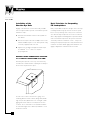
Installation of the
Shoulder Eye Bolts
Rigging of the FRi-Series is done with readily available
3/8-16 forged shoulder eye bolts. To install the eye bolts,
follow these steps:
1. Determine the intended location for the eyebolts on
the cabinet.
2. Remove and replace the 3/8-16 Phillips head screws
ONE AT A TIME. Replace screws with eye bolt, using
a washer (supplied) under each one.
3. Tighten each eye bolt “hand tight” and then torque
an additional
1
/
2
to
3
/
4
turn to accomplish
proper alignment.
WARNING: NEVER REMOVE MORE THAN ONE
3/8-16 PHILLIPS HEAD SCREW AT A TIME!
Removing two adjacent screws may cause the heavy
steel bracket to fall into the box, requiring disassembly of
the enclosure to put it back in place.
The FRi Series features internal heavy gauge steel
reinforcing brackets that are not only designed to provide
high safety factor support for the 3/8-16 forged eyebolt
rigging, but also to unitize the internal panels for each
enclosure. These corner braces are required to maintain
the structural integrity of the cabinet to performance levels
listed in this manual.
Basic Principles for Suspending
FRi Loudspeakers
Many “suspendible” loudspeaker designs offer “t-nut” style
mounting without using top and side enclosure panel
braces, thus producing lower safety factors. Therefore,
each FRi full range loudspeaker enclosure is furnished
with 12 fully supported mounting points to provide maximum
vertical or horizontal suspension. All systems have been
structurally certified to a minimum of 8 to 1 safety factor
loading. Each input panel provides safety information and
maximum safe multi-cabinet rigging data. Maximum safe
rigging configurations should never be exceeded.

F R i
SPEAKER
SYSTEMS
Rigging
8
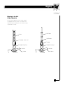
Rigging to the 3/8
Forged Eyebolts
Recommended rigging to the 3/8 forged eyebolts
(4 supplied) with each system is as follows and is
dependent upon following all recommended loading
requirements for safety.
Wire Rope
Method 1
Cabinet
Washer
Forged Lifting Eye
Threaded “Quick Link”
Chain
Clip Saddles
Thimble
Method 2
Cabinet
Washer
Forged Lifting Eye

Rigging
9
F R i
SPEAKER
SYSTEMS
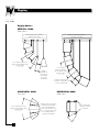
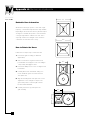
Rigging Options
GRID, STRUCTURAL SUPPORT,
CABLE(S) BY OTHERS
GRID, STRUCTURAL SUPPORT,
CABLE(S) BY OTHERS
SPLAY ANGLE SHOULD BE
EQUAL TO APPLICABLE HORN
PATTERN ANGLE
(i.e. 60 OR 40)
SPLAY ANGLE SHOULD BE
EQUAL TO APPLICABLE HORN
PATTERN ANGLE
(i.e. 60 OR 40)
GRID, STRUCTURAL
SUPPORT, CABLE(S)
BY OTHERS
CABINET SIDE DRAFT ANGLES
DESIGNED FOR NOMINAL
ARRAY PERFORMANCE
WHEN “TIGHT PACKED” WITH
FRi 1815 SUB BETWEEN TWO
FULL RANGE CABINETS.
NON-ROTATED HORNS
CABINET
SPACING TO
BE AS GREAT
AS POSSIBLE
TO SATISFY
APPLICATION
CABINET SPACING TO BE
AS GREAT AS POSSIBLE TO
SATISFY APPLICATION
SPLAY ANGLE
SHOULD BE EQUAL
TO APPLICABLE HORN
PATTERN ANGLE
(i.e. 60 OR 40)
VERTICAL HANG
(Side Views)
HORIZONTAL HANG
(Top View)
HORIZONTAL HANG
(Side View)

F R i
SPEAKER
SYSTEMS
Amplifier Recommendations
10
Rigging Options
EV has coordinated with ATM Flyware and Polar Focus
in developing pre-designed flying hardware to support
the most common array configurations of one sub
flanked by two full-range loudspeakers. To receive
additional information, please contact either of these
fine companies.
ATM Flyware
In the United States:
21000 S. Wilmington Ave.
Carson, CA 90810
Tel: 310-834-5914
Fax: 310-834-3042
In Europe:
102 Grafton Road
London NW5 4 BA UK
Tel: (44) 0171-482-3300
Fax: (44) 0171-482-4484
Polar Focus, Inc.
P.O. Box 3, 217 Russell Street
Hadley, MA 01035
U.S.A
Tel: 413-586-4444
Fax: 509-357-5657
The EV CPS-2, two-channel power amplifier is recommended
for use with all FRi series loudspeakers, whether running
in passive or active crossover mode. This amplifier is
sufficient to operate up to two paralleled FRi series
cabinets per channel, supplying the necessary headroom
to provide appropriate long term program and instantaneous
peak power for most program materials. If array
configurations are designed as such to run in all passive
mode with more than two cabinets, an amplifier sufficient
to drive the total load requirements of the configuration
must be selected taking into consideration the individual
cabinet power requirements. For example, a 3 box array
containing two full range and one sub can be operated
in bi-amp mode with one channel of the CPS2 handling
the high frequency output of the crossover and feeding
the two full range cabinets and the other channel handling
the low frequency output of the crossover and feeding
the sub(s).
Amplifier Recommendations
Rigging

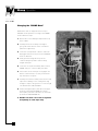
Changing the “BIAMP Mode”
All FRi-Series units are shipped from the factory in
“PASSIVE” mode operation. To change to the “BIAMP”
mode, follow these steps:
1. Remove the screws holding the input terminal cup
to the cabinet.
2. Carefully remove the assembly far enough to
get a good look at the back of the circuit board
(about six to eight inches).
3. Locate the seven-pin in-line connector, which will
be plugged onto the row of pins marked “PASSIVE”
on the circuit board.
4. Gently push the locking tab away from the
connector body and pull the connector body
straight off the pins.
5. Locate the row of pins immediately above marked
“BIAMP” and press connector body onto them.
6. Check to be sure all seven pins are engaged and
that the connector body is securely seated all the
way down in the receptacle.
7. Carefully re-install the assembly in the enclosure and
replace the mounting screws, making them snug
enough to compress the gasket for a secure air-tight
seal, but DO NOT OVER TIGHTEN!
8. Connect the high-frequency drive line to the upper
terminals (marked “INPUT BIAMP HF”) and the
low-frequency drive line to the lower set of terminals
(marked FULL RANGE/BIAMP LF).
9. Double-check for correct line assignment
and polarity on each input strip.
Biamp Operation
11
F R i
SPEAKER
SYSTEMS
Biamp Operation

F R i
SPEAKER
SYSTEMS
Electronic Crossover
12
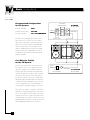
Typical FRi Input Panel
All FRi full range enclosures feature very high
quality barrier strip input terminations for ease
of installation and secure connections.
The active crossover centerpoint is 1600 Hz
with a crossover type of 4th-order (24 dB/oct)
Linkwitz-Riley, recommended.
The full range active crossover should be set for 1600 Hz;
however, if adjustments are made or variations are
implemented do not use frequencies below 1480 Hz!
Crossover slope should be 24 dB/octave. Should budget
allowances permit, limiters may prove a useful and an
appropriate addition to the signal path, especially for the
high frequency section. For more rudimentary clusters we
recommend the EV EX23 Active Crossover which contains
a 4th-order (24 dB/oct) Linkwitz-Riley and a stereo two-way
section with continuously variable crossover frequencies
from 80 - 8000 Hz. Each of the two outputs per channel
has separate mute switches and level controls. For
bi-amping the FRi Series in more complex array
configurations with delays and a greater need for
equalization, we recommend the EV Dx38 Digital Sound
System Controller, which incorporates all necessary
crossover, parametric EQ, shelving EQ, low- and high-
pass filters, alignment (delay), compressor and limiter
functions. (Settings for the Dx38 are available on the
EV Web site: www.electrovoice.com.)
Setting the
Electronic Crossover

• Bi-amp Operation BEST
• All Passive Operation BETTER
• Tri-amp Operation NOT RECOMMENDED
Due to the inherent designs and efficiencies of the
FRi systems, there is no cost effective reason to
utilize all active operation in either mono or stereo
mode. Actual cost of electronics and amplification
will be determined by the total number of FRi
cabinets configured within the array. Due to load
requisites some array configurations may not be
feasibly powered in all passive mode with typical
amplifiers available.
Recommended Configurations
for FRi Systems
Based on cost effectiveness of the entire system
(loudspeakers, processors, amplifiers), bi-amp
operation combines the overall best frequency
response and value. In simpler stereo applications
with one full range and one sub per side, we would
recommend a bi-amped mode of operation for
performance; however, all passive configurations
will typically supply adequate fidelity at an extremely
cost effective means. If multi-box arrays are used in
a stereo configuration, the recommendations for
mono program configurations apply to each side.
Cost Effective Fidelity
for the FRi System
To increase low frequency response, consider a
hard-surface coupled mounting surface of the sub(s).
These may be floors, walls or ceilings. Acoustically
coupling low-frequency cabinets to architectural
structures provide an extremely cost effective means
of providing more low-frequency energy in your system
without additional loudspeakers or electronics.
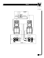
Basic Configurations
13
F R i
SPEAKER
SYSTEMS
OPTIONAL
PROCESSING
CROSSOVER
AUDIO
INPUT
AMPLIFIER
BI-AMPED
MONO ARRAY
ALL PASSIVE
MONO ARRAY
AMPLIFIER
OPTIONAL
PROCESSING
AUDIO
INPUT

F R i
SPEAKER
SYSTEMS
14
Basic Configurations
OPTIONAL
PROCESSING
AUDIO
INPUT
AMPLIFIER
PASSIVE
STEREO
OPTIONAL
PROCESSING
AUDIO
INPUT
AMPLIFIER
ACTIVE STEREO
CROSSOVER
AUDIO
INPUT
OPTIONAL
PROCESSING
AMPLIFIER
CROSSOVER

Rotatable Horn Information
All FRi-Series full-range speakers come with a high-
frequency, constant-directivity horn that is fully rotatable.
Depending on the model, the horn may be rotated up to
90 degrees to maintain the speaker’s same horizontal
coverage angle with the cabinet on its side. This is
especially useful in low-ceilinged rooms and in the
construction of vertical line source arrays.
How to Rotate the Horns
Follow these six simple steps to rotate the horn:
1. Remove the grille assembly (as outlined in
Appendix B).
2. Stuff a clean, lint-free rag in the horn throat to
prevent debris and dropped screws from falling in
and possibly damaging the driver.
3. Remove the Philips head screws securing the horn
to the baffle.
4. Carefully lift the horn off the baffle, taking care
not to disturb the gasket, and rotate the horn
one-quarter turn.
5. Align the mounting holes and replace the screws.
Tighten the screws enough to compress the
gasket and provide a solid, air-tight seal, but
DO NOT OVER-TIGHTEN.
6. Carefully remove the rag and replace the
grille assembly.
60º
40º
60º
40º
60º
60º
40º
40º
15
F R i
SPEAKER
SYSTEMS
Appendix A: Mechanical Adjustments

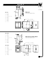
Appendix B: Dimensional Specifications
3/8-16 UNC x 1.5 in. DEEP
CENTER OF GRAVITY
A
H
B
F
D
E
G
KKC
L
M
J
D
N
F
B
G
E
A
H
3/8-16 UNC x 1.5 in. DEEP
CENTER OF GRAVITY
FRi-152/64
A: 19.03 in.
B 23.23 in.
C: 27.92 in.
D: 7.25 in.
E: 15 degrees per side
F: 1.70 in.
G: 16.96 in.
H: 13.71 in.
J: 24.48 in.
K: 18.21 in.
L: 14.00 in.
M: 13.50 in.
FRi-181S
A: 23.51 in.
B: 30.00 in.
C: 27.92 in.
D: 15.93 in.
E: 7.5 degrees per side
F: 2.33 in.
G: 23.30 in.
H: 19.23 in.
J: 23.30 in.
K: 24.48 in.
L: 13.25 in.
M: 15.75 in.
FRi-122/64
A. 15.83 in.
B. 17.54 in.
C: 27.92 in.
D: 7.00 in.
E: 15 degrees per side
F: 1.75 in.
G: 11.62 in.
H: 10.54 in.
J: 13.37 in.
K: 24.50 in.
L: 13.63 in.
M: 9.13 in.
FRi-152/64 and FRi-122/64
Dimensional Specifications
FRi-181S
Dimensional Specifications
F R i
SPEAKER
SYSTEMS
16
KC
L
M
J

17
F R i
SPEAKER
SYSTEMS
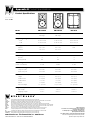
SPL IN dB
FREQUENCY IN HERTZ
FRi-122 Frequency Response
+40
+120
+45
+50
+55
+60
+65
+70
+75
+80
+85
+90
+95
+100
+105
+110
+115
20 20k50 100 200 500 1k 2k 5k 10k
FREQUENCY IN HERTZ
FRi-122 Impedance Graph
1
200
2
5
10
20
50
100
20 20k50 100 200 500 1k 2k 5k 10k
IMPEDANCE
SPL IN dB
FREQUENCY IN HERTZ
FRi-152 Frequency Response
+40
+120
+45
+50
+55
+60
+65
+70
+75
+80
+85
+90
+95
+100
+105
+110
+115
20 20k50 100 200 500 1k 2k 5k 10k
FREQUENCY IN HERTZ
FRi-152 Impedance Graph
1
200
2
5
10
20
50
100
20 20k50 100 200 500 1k 2k 5k 10k
IMPEDANCE
SPL IN dB
FREQUENCY IN HERTZ
FRi-181s Frequency Response
+40
+120
+45
+50
+55
+60
+65
+70
+75
+80
+85
+90
+95
+100
+105
+110
+115
20 20k50 100 200 500 1k 2k 5k 10k
1
200
2
5
10
20
50
100
20 20k50 100 200 500 1k 2k 5k 10k
FREQUENCY IN HERTZ
FRi-181s Impedance Graph
IMPEDANCE
Appendix C: Frequency Curve

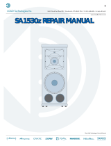
FRi-122/64 Beamwidth vs. Frequency
FREQUENCY IN HERTZ
BEAMWIDTH IN DEGREES (6 dB)
360
300
200
20 5030 100 200 500 1000 2000 5000
10,000 20,000
100
80
60
40
20
F R i
SPEAKER
SYSTEMS
18
Appendix D: Beamwidth Curve
FRi-122/64 Directivity Factor and Directivity Index
FREQUENCY IN HERTZ
DIRECTIVITY INDEX D dB
i
30
20
20 5030 100 200 500 1000 2000 5000
10,000 20,000
10
0
FRi-152/64 Beamwidth vs. Frequency
FREQUENCY IN HERTZ
BEAMWIDTH IN DEGREES (6 dB)
360
300
200
20 5030 100 200 500 1000 2000 5000
10,000 20,000
100
80
60
40
20
FRi-152/64 Directivity Factor and Directivity Index
FREQUENCY IN HERTZ
DIRECTIVITY INDEX D dB
i
30
20
20 5030 100 200 500 1000 2000 5000
10,000 20,000
10
0

www.electrovoice.com
•
Telex Communications, Inc.
•
www.telex.com
©Telex Communications, Inc. 9/2003 Rev. B Part Number 38109-925
USA 12000 Portland Ave South, Burnsville, MN 55337, Phone: 952-884-4051, FAX: 952-884-0043
Canada 705 Progress Avenue, Unit 46, Scarborough, Ontario, Canada, M1H2X1, Phone: 416-431-4975, 800-881-1685, FAX: 416-431-4588
Switzerland Keltenstrasse 11, CH-2563 IPSACH, Switzerland, Phone: 41/32-331-6833, FAX: 41/32-331-1221
Germany Hirschberger Ring 45, D94315, Straubing, Germany, Phone: 49 9421-706 0, Fax: 49 9421-706 287
France Parc de Courcerin,Allee Lech Walesa, Lognes, 77185 Marne La Vallee, France, Phone: 33/1-6480-0090, FAX: 33/1-6480-4538
Australia Unit 23, Block C, Slough Business Park, Slough Avenue, Silverwater, N.S.W. 2128, Australia, Phone: 61/2-9648-3455, FAX: 61/2-9648-5585
Hong Kong Unit E & F, 21/F, Luk Hop Industrial Bldg., 8 Luk Hop St., San PO Kong, Kowloon, Hong Kong, Phone: 852-2351-3628, FAX: 852-2351-3329
Japan 2-5-60 Izumi, Suginami-ku,Tokyo, Japan 168, Phone: 81-3-3325-7900, FAX: 81-3-3325-7789
Singapore 3015A Ubi Rd 1, 05-10, Kampong Ubi Industrial Estate, Singapore 408705, Phone: 65-746-8760, FAX: 65-746-1206
Mexico Av. Parque Chapultepec #66-201, Col. El. Parque Edo. Mex. 53390, Phone: (52) 5358-5434, FAX: (52) 5358-5588
UK 4, The Willows Centre, Willow Lane, Mitcham, Surrey CR4 4NX, UK, Phone: 44 181 640 9600, FAX: 44 181 646 7084
Africa, Mid-East 12000 Portland Ave South, Burnsville, MN 55337, Phone: 952-887-7424, FAX: 952-887-9212
Latin America 12000 Portland Ave South, Burnsville, MN 55337, Phone: 952-887-7491, FAX: 952-887-9212
U.S.A. and Canada only.
For customer orders, contact the Customer Service department at
800/392-3497 Fax: 800/955-6831
For warranty repair or service information, contact the Service
Repair department at 800/685-2606
For technical assistance, contact Technical Support at 800/392-3497
Please refer to the Engineering Data Sheet for warranty information.
Specifications subject to change without notice.
F R i
SPEAKER
SYSTEMS
Appendix E Product Specifications
Product Specifications
Configuration Two-way Two-way Sub
Full-range Full-range
Frequency Range (Passive)
- 3 dB 62 Hz-15 kHz 70 Hz-15 kHz 45 Hz-160 Hz
-10 dB 50 Hz-16 kHz 50 Hz-16 kHz 36 Hz-250 Hz
Coverage (Hº x Vº)
Normal 60º x 40º 60º x 40º N/A
Rotated 40º x 60º 40º x 60º
LF Cone 12-inch 15-inch 18-inch
Normal Impedance (Ohms)
Passive 8 8 8
Biamp (LF/HF) 8/8 8/8 8
Sensitivity
(1W @ 1m/ dB SPL) 97 dB 98 dB 97 dB
Power Handling (Passive)
Long-term (EIA) 300 watts 350 watts 400 watts
Short-term peak 1200 watts 1400 watts 1600 watts
Dimensions inches (mm)
Height 28.0 (711) 28.0 (711) 28.0 (711)
Width in front 15.9 (404) 19.0 (483) 23.5 (597)
Width in back 7.0 (178) 7.3 (185) 16.0 (406)
Depth 17.6 (447) 23.2 (589) 30.0 (762)
Trapezoid Angle 15º per side 15º per side 7.5º per side
Weight (lbs/kg)
Net Weight 60/27.3 70/31.8 100/45.5
Shipping Weight 72/32.7 82/37.3 110/50.0
Model FRi-122/64 FRi-152/64 FRi-181S
-
 1
1
-
 2
2
-
 3
3
-
 4
4
-
 5
5
-
 6
6
-
 7
7
-
 8
8
-
 9
9
-
 10
10
-
 11
11
-
 12
12
-
 13
13
-
 14
14
-
 15
15
-
 16
16
-
 17
17
-
 18
18
-
 19
19
-
 20
20


Electro-Voice FRi Speaker Systems User manual
- Category
- Loudspeakers
- Type
- User manual
Ask a question and I''ll find the answer in the document
Finding information in a document is now easier with AI
Related papers
-
Electro-Voice EVERYWHERE FRI-122/64 User manual
-
Bosch ZX3-60PI-W User manual
-
-
-
-
-
-
-
-
Other documents
-
Omnitronic 80710465 Datasheet
-
Voyager GR104 User manual
-
LY International Electronics H-3305/H-3306/H-3307 Owner's manual
-
AUSTRALIAN MONITOR NRG500 Quick start guide
-
OWI T8760 User manual
-
Biamp WX-1200 Owner's manual
-
Biamp iBOX SERIES Owner's manual
-
321 Studios 29AV User manual
-
DYNACORD Speaker User manual
-
 Alvarez SA1530Z User manual
