Page is loading ...

Betriebsanleitung | Operating instructions | Mode d’emploi |
Istruzioni per l'uso | Instrucciones de servicio | Bruksanvisning
R499050020/09.2014, Replaces: 11.2013, DE/EN/FR/IT/ES/SV
Buskoppler DDL mit E/A-Funktionalität (optional), B-Design
Bus coupler DDL with I/O function (optional), B-design
Coupleur de bus DDL avec fonctionnalité E/S (en option), design B
Accoppiatore bus DDL con funzionalità I/O (opzionale), design B
Acoplador de bus DDL con funcionalidad E/S (opcional), diseño B
Fältbussnod DDL med I/O-funktion (som tillval), B-design
DDL
DeutschEnglishFrançaisItalianoEspañolSvenska

Contents
AVENTICS | DDL | R499050020–BDL–001–AD 59
English
Contents
1 About This Documentation ......................................... 61
1.1 Documentation validity ......................................................... 61
1.2 Required and supplementary documentation............... 61
1.3 Presentation of information ................................................ 62
1.3.1 Notes on Safety ..................................................................... 62
1.3.2 Symbols ................................................................................... 63
1.3.3 Abbreviations ......................................................................... 63
2 Notes on Safety ........................................................... 64
2.1 About this section................................................................... 64
2.2 Intended use............................................................................. 64
2.3 Improper use ........................................................................... 65
2.4 Personnel qualifications....................................................... 65
2.5 General safety instructions ................................................. 66
2.6 Safety instructions related to the product
and technology........................................................................ 66
3 Applications ................................................................. 68
4 Delivery Contents ........................................................ 68
5 Device description ....................................................... 69
5.1 Overview of the valve system and modules................... 70
5.2 Device components................................................................ 71
5.2.1 Bus coupler ............................................................................ 71
5.2.2 Input/output modules ......................................................... 72
5.2.3 Input modules ........................................................................ 73
5.2.4 Output modules ..................................................................... 73
6 Assembly ..................................................................... 75
6.1 Assembling the valve system with the bus coupler .... 75
6.1.1 Dimensions ............................................................................. 75
6.2 Labeling the module.............................................................. 76
6.3 Connecting the modules electrically ................................ 77
6.3.1 Connecting the data lines on the bus coupler ............. 78
6.3.2 Connecting the power supply on the bus coupler ...... 79
6.3.3 Connecting the 8x input/output modules ...................... 81
6.3.4 Connecting the output module load supply .................. 83
6.3.5 FE connection ........................................................................ 84

Contents
60 AVENTICS | DDL | R499050020–BDL–001–AD
7 Commissioning and Operation ................................... 85
7.1 Making presettings ................................................................ 85
7.1.1 Setting the baud rate (DDL mode) ................................... 85
7.1.2 Assigning an address to the bus coupler ...................... 86
7.1.3 Setting the output data length for valves ...................... 88
7.1.4 Output data section in the controller .............................. 89
7.1.5 Input data section in the controller ................................. 90
7.1.6 Selecting the valve supply ................................................. 90
7.2 Initializing the bus coupler .................................................. 92
7.3 Test and diagnosis ................................................................. 92
7.3.1 LED diagnosis ........................................................................ 92
7.3.2 Overload protection ............................................................. 93
7.3.3 Software diagnosis .............................................................. 94
7.3.4 Check sensors on the input module ............................... 97
7.3.5 Check actuators on the output module .......................... 98
7.4 Commissioning the bus coupler ........................................ 99
8 Disassembly and Exchange ..................................... 100
8.1 Exchanging the bus coupler..............................................100
8.2 Mounting input/output module(s)....................................102
9 Care and Maintenance .............................................. 105
9.1 Servicing the modules ........................................................105
9.2 Maintaining the modules....................................................105
10 Technical Data ........................................................... 106
10.1 Characteristics ......................................................................106
10.2 Bus coupler ............................................................................106
10.3 8x input modules, inputs 8x M8 or inputs 4x M12......106
10.4 8x output modules, outputs 8x M8
or outputs 4x M12.................................................................107
11 Spare parts and accessories ................................... 107
11.1 Bus coupler ............................................................................107
11.2 Power plug for bus coupler and output module .........108
11.3 8x input/output module, 8DI/8DO....................................108
12 Disposal ...................................................................... 108
13 Index ........................................................................... 109

About This Documentation
AVENTICS | DDL | R499050020–BDL–001–AD 61
English
1 About This Documentation
1.1 Documentation validity
This documentation is intended for installers, operators, service
technicians, and systems owners.
This documentation contains important information on the safe
and appropriate assembly, operation, and maintenance of the
bus coupler and how to remedy simple malfunctions yourself.
Read this documentation completely, especially the chapter
“Notes on Safety” before working with the product.
1.2 Required and supplementary
documentation
O Only commission the product once you have obtained the
following documentation and understood and complied with
its contents.
Further information on the components can be found in the
online catalog at www.aventics.com/pneumatics-catalog.
Table 1: Required and supplementary documentation
Academic title Document number Document type
Valve system HF03 LG D-SUB R412008233 Instructions
HF04 D-SUB valve system R412015493 Instructions
DDL “Drive & Diagnostic Link”
system description (German)
R499050030 Instructions
DDL “Drive & Diagnostic Link”
system description (English)
R499050031 Instructions
System documentation

About This Documentation
62 AVENTICS | DDL | R499050020–BDL–001–AD
1.3 Presentation of information
To allow you to begin working with the product quickly and
safely, uniform safety instructions, symbols, terms, and
abbreviations are used in this documentation. For better
understanding, these are explained in the following sections.
1.3.1 Notes on Safety
This documentation contains safety instructions before any
steps that involve a risk of personal injury or damage to
equipment. The measures described to avoid these hazards
must be observed.
Safety instructions are set out as follows:
W Warning symbol: draws attention to the hazard
W Signal word: identifies the degree of hazard
W Hazard type and source: identifies the hazard type and
source
W Consequences: describes what occurs when the safety
instructions are not complied with
W Precautions: states how the hazard can be avoided
SIGNAL WORD
Hazard type and source
Consequences of non-observance
O Precautions
Table 2: Hazard classes according to ANSI Z535.6-2006
Safety sign, signal word Meaning
DANGER
Indicates a hazardous situation
which, if not avoided, will certainly
result in death or serious injury.
WARNING
Indicates a hazardous situation
which, if not avoided, could result in
death or serious injury.

About This Documentation
AVENTICS | DDL | R499050020–BDL–001–AD 63
English
1.3.2 Symbols
The following symbols indicate information that is not relevant
for safety but that assists in comprehending the documentation.
1.3.3 Abbreviations
The following abbreviations are used in this documentation:
CAUTION
Indicates a hazardous situation
which, if not avoided, could result in
minor or moderate injury.
NOTICE
Indicates that damage may be
inflicted on the product or the
environment.
Table 3: Meaning of the symbols
Symbol Meaning
If this information is disregarded, the product cannot be
used or operated optimally.
O
Individual, independent action
1.
2.
3.
Numbered steps:
The numbers indicate sequential steps.
Table 4: Abbreviations
Abbreviation Meaning
VS Valve system
DDL Drive & Diagnostic Link
Table 2: Hazard classes according to ANSI Z535.6-2006
Safety sign, signal word Meaning

Notes on Safety
64 AVENTICS | DDL | R499050020–BDL–001–AD
2 Notes on Safety
2.1 About this section
The product has been manufactured according to the accepted
rules of current technology. Even so, there is risk of injury and
damage to equipment if the following chapter and safety
instructions of this documentation are not followed.
O Read these instructions completely before working with the
product.
O Keep this documentation in a location where it is accessible
to all users at all times.
O Always include the documentation when you pass the
product on to third parties.
2.2 Intended use
The product is an electropneumatic system component.
The product may be used as follows:
W only for industrial applications.
W within the performance limits listed in the technical data.
The product is intended for professional use only.
Intended use includes having read and understood this
documentation, especially the chapter “Notes on Safety”.

Notes on Safety
AVENTICS | DDL | R499050020–BDL–001–AD 65
English
2.3 Improper use
Any use other than that described under Intended use is
improper and is not permitted.
If unsuitable products are installed or used in safety-relevant
applications, this may result in unintended system operating
states that could lead to injuries and/or equipment damage.
Therefore, only use a product in safety-relevant applications if
such use is specifically stated and permitted in the product
documentation. For example, in areas with explosion protection
or in safety-related components of control systems (functional
safety).
AVENTICS GmbH is not liable for any damages resulting from
improper use. The user alone bears the risks of improper use of
the product.
It is considered improper use when the product:
W is used for any application not stated in these instructions or
W is used under operating conditions that deviate from those
described in these instructions.
W The bus products described here are not considered safety
modules in accordance with EN 61508 and DIN EN 954-1.
2.4 Personnel qualifications
The work described in this documentation requires basic
electrical and pneumatic knowledge, as well as knowledge of
the appropriate technical terms. In order to ensure safe use,
these activities may therefore only be carried out by qualified
technical personnel or an instructed person under the direction
and supervision of qualified personnel.
Qualified personnel are those who can recognize possible
hazards and institute the appropriate safety measures, due to
their professional training, knowledge, and experience, as well
as their understanding of the relevant regulations pertaining to
the work to be done. Qualified personnel must observe the rules
relevant to the subject area.

Notes on Safety
66 AVENTICS | DDL | R499050020–BDL–001–AD
2.5 General safety instructions
W Observe the regulations for accident prevention and
environmental protection.
W Observe the safety instructions and regulations of the
country in which the product is used or operated.
W Only use AVENTICS products that are in perfect working
order.
W Follow all the instructions on the product.
W Persons who assemble, operate, disassemble, or maintain
AVENTICS products must not consume any alcohol, drugs,
or pharmaceuticals that may affect their ability to respond.
W To avoid injuries due to unsuitable spare parts, only use
accessories and spare parts approved by the manufacturer.
W Comply with the technical data and ambient conditions
listed in the product documentation.
W If unsuitable products are installed or used in safety-
relevant applications, this may result in unintended system
operating states that may lead to injuries and/or equipment
damage. Therefore, only use a product in safety-relevant
applications if such use is specifically stated and permitted
in the product documentation.
W You may only commission the product if you have
determined that the end product (such as a machine or
system) in which the AVENTICS products are installed
meets the country-specific provisions, safety regulations,
and standards for the specific application.
2.6 Safety instructions related to the product
and technology
W Do not modify or convert the device.
W Only use the device within the performance range provided in
the technical data.
W Do not place any mechanical loads on the device under any
circumstances. Do not place any loose objects on it.

Notes on Safety
AVENTICS | DDL | R499050020–BDL–001–AD 67
English
W This device may only be used for industrial applications
(class A). An individual license must be obtained from the
authorities or an inspection center for systems that are to be
used in a residential area (residential, business, and
commercial areas).
W Ensure that the power supply is within the stipulated
tolerance for the modules.
W Observe the safety notes in the operating instructions for
your valve system.
W A 24 V power pack supplies all components with electricity.
The power pack must be fitted with a safe isolation in
accordance with EN 60742, VDE 0551 classification. The
corresponding electrical circuits are thus SELV/PELV
circuits in accordance with IEC 60364-4-41.
W Switch off the operating voltage before connecting or
removing the plugs.
During assembly
W The warranty only applies to the delivered configuration. The
warranty will not apply if the product is incorrectly assembled.
W Make sure the relevant system component is not under
pressure or voltage before assembly or disassembly.
Ensure that the system is prevented from power restoration
during assembly work.
W Ground the modules and valve system. Observe the
following standards when installing the system:
– DIN EN 50178, classification VDE 0160
– VDE 0100
During commissioning W Installation may only be performed in a voltage-free and
pressure-free state and only by a qualified technician. In
order to avoid accidents caused by dangerous movements
of the actuators, electrical commissioning may only be
carried out in a pressure-free state.
W Do not put the system into operation before it is completely
assembled as well as correctly wired and configured, and
after it has been tested.
W The device is subject to the restrictions of the IP 65
protection class. Before commissioning, make sure that all
the connection seals and plugs are leaktight to prevent
fluids and foreign bodies from penetrating the device.

Applications
68 AVENTICS | DDL | R499050020–BDL–001–AD
During operation W Make sure that there is a sufficient exchange of air or
enough cooling if your valve system has any of the following:
– Full equipment status
– Continuously loaded solenoid coils
During cleaning W Never use solvents or strong detergents. Only clean the
device using a slightly damp cloth. Only use water and, if
necessary, a mild detergent.
3 Applications
The bus coupler is used to electrically control valves via the DDL
link structure. Input/output modules allow electrical input and
output signals to be output via the valve system’s DDL
connection.
The bus coupler is designed only for use as a participant in the
DDL link structure.
4 Delivery Contents
The delivery contents include:
W 1 valve system according to configuration and order
W 1 set of operating instructions for the valve system
W 1 set of operating instructions for the bus coupler
The following is included in the delivery contents of a bus
coupler parts kit:
W 1 bus coupler with seal and 2 mounting screws
W 1 set of operating instructions for the bus coupler
The VS is individually configured. You can find the exact
configuration in the AVENTICS Internet configurator under
your order number.

Device description
AVENTICS | DDL | R499050020–BDL–001–AD 69
English
5 Device description
The bus coupler makes it possible to control the VS via the DDL
link structure on a fieldbus. A bus coupler that complies with the
appropriate fieldbus protocol is required for this. It is not
included in this scope of delivery. In addition to connections for
data lines and power supplies, the bus coupler also enables you
to set various parameters, and permits diagnosis via LEDs. The
bus coupler can also be extended with input and output
modules. A detailed description of the bus coupler and input/
output modules can be found in the chapter “Device description”
from page 69.
The following overview outlines the entire valve system and its
components. The VS proper is described in separate operating
instructions.

Device description
70 AVENTICS | DDL | R499050020–BDL–001–AD
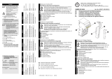
5.1 Overview of the valve system and modules
The valve system consists of the following parts as illustrated in
Fig. 1 (depending on the order):
Fig. 1: Overview: bus coupler sample configuration with I/O modules and mounted VS
1 E end plate
2 Output module
1)
3 Input module
1)
4 Bus coupler, valve driver, type B-design
1)
A maximum of 3 input and 3 output modules can be connected.
5 EP end plate for HF03 LG or HF04
6 Valve terminal
2)
7 FE connection on the end plate
2)
With separate operating instructions.
7
1
2
3
4
6
5

Device description
AVENTICS | DDL | R499050020–BDL–001–AD 71
English
5.2 Device components
5.2.1 Bus coupler
Fig. 2: Bus coupler overview
1 LED displays for diagnostic messages
2 Bus slave label
3 X71 (BUS IN) connection for the bus coupler to control valves
and the I/O modules
1)
1)
For plug assignment see page 78.
4 X72 (BUS OUT) connection to control valves and
the I/O modules
1)
5 X10 (POWER) connection to supply voltage to the
valve solenoids, logic and inputs
6 Screw cap B: Switches S1 to S4 to select the
valve power supply
7 Screw cap A: Switch S5 to set the DDL address and S6 to
select the DDL baud rate and the output data length
2
3
4
5
6
7
1

Device description
72 AVENTICS | DDL | R499050020–BDL–001–AD
The bus coupler is designed only for use as a participant in a
DDL line.
A shielded, 5-wire cable is used as a fieldbus cable
(see DDL system description). The line length can be up to 40 m.
A maximum of 14 participants may be connected.
Bus coupler address The bus coupler address is set with the S5 switch.
Baud rate The baud rate can be set with S6, bit 1.
Diagnosis The logic and valve control power supplies are monitored. If
they exceed or fall below a set limit, an error signal will be
generated and confirmed with the diagnostic LED and the
diagnostic information.
Number of valves
that can be controlled
Up to 12 double or 24 single solenoid valves or a suitable
combination of double and single solenoid valves can be
connected. In each case, up to 24 valve solenoids can be
controlled.
5.2.2 Input/output modules
Input/output modules with releasable plug connections allow
electrical input and output signals to be output via the valve
system's DDL line.
Number of
connectable modules
Input and output modules can be connected in any combination
on the valve driver (in the DDL line) – however, with a maximum
of 3 input modules and 3 output modules (total output signals
incl. valves may not exceed 32 outputs).
O Make sure to stay within the load limits.
The bus coupler supplies the inputs for the input modules.
The maximum total current for all inputs is 0.7 A.
The output module is supplied via an M12 connection, with one
power supply each for 4 outputs (see Tab. 11 on page 83).
The bus coupler is limited to 4 bytes of output data and
4 bytes of input data due to system design. If 3 output
modules (3 bytes of output data) are used, there is only one
byte available for the valves, i.e. 4 double solenoid valves or
8 single solenoid valves can be controlled.

Device description
AVENTICS | DDL | R499050020–BDL–001–AD 73
English
5.2.3 Input modules
The input modules used to connect electric sensor signals are
available in two versions:
W 8x M8 inputs or
W 4x M12 inputs with double assignment
Fig. 3: 8x input module: 8x M8 inputs (left), 4x M12 inputs (right)
5.2.4 Output modules
The output modules used to connect the actuators are available
in two versions:
W 8x M8 outputs or
W 4x M12 outputs with double assignment
1 Label
2 Left: 8 inputs on 8x M8 sockets
1)
Right: 8 inputs on 4x M12 sockets
1)
1)
For plug assignment see page 78.
3 LED (yellow, status) for each input
2
3
1
2
3
1

Device description
74 AVENTICS | DDL | R499050020–BDL–001–AD
Fig. 4: 8x output module: 8x M8 outputs (left), 4x M12 outputs (right)
1 Label
2 LED (yellow, status) for each output
3 Two-color LED for load supply U
Q2
4 Load supply connection via M12 plug
1)
1)
For plug assignment see page 78.
5 Left: 8 outputs on 8x M8 sockets
1)
Right: 8 outputs on 4x M12 sockets
1)
6 Two-color LED for load supply U
Q1
1
2
3
4
6
5
2
1
4
3
5
6

Assembly
AVENTICS | DDL | R499050020–BDL–001–AD 75
English
6 Assembly
6.1 Assembling the valve system with the
bus coupler
You will receive your individually configured HF03 LG or HF04
series valve system completely fitted with all components:
W Valve terminal
W Bus coupler
W I/O modules (if needed)
The operating instructions accompanying the VS describe in full
how to assemble the entire valve system. Any mounting
orientation may be used with the VS. The dimensions of the
complete VS vary according to module equipment (see Fig. 5).
6.1.1 Dimensions
Fig. 5: Dimensioned drawing of the valve system (bus coupler and valves)
135
A + (60 x m)
B + (60 x m)
96060

Assembly
76 AVENTICS | DDL | R499050020–BDL–001–AD
Each input/output module extends the valve system by 60 mm
(60 x m). The E end plate has an installation depth of 18 mm.
6.2 Labeling the module
Bus coupler O Inscribe the address provided/used for the bus coupler on
the bus coupler in the BTN field.
Input/output modules O Label the connections directly on the labels of the input/
output modules.
The markings on the connections indicate which labels are
assigned to the connections.
Fig. 6: Labels on the bus coupler, input module (8x M8 inputs) and output module (8x M8 outputs),
examples
SENSOR
SENSOR
UV 1-4
UV 1-4
UV 5-8
UV 5-8
UV 9-12
UV 9-12
DDL
DDL
RMV04-DDL BTN
RMV04-DDL BTN

Assembly
AVENTICS | DDL | R499050020–BDL–001–AD 77
English
6.3 Connecting the modules electrically
CAUTION
Applied voltage
Danger of injury from electric shocks.
O Make sure the relevant system component is not under
voltage or pressure before electrically connecting
modules to the valve terminal.
O Do not insert or disconnect plug connectors under load.
NOTICE
Faulty wiring
Faulty wiring can lead to malfunctions as well as damage to
the DDL line. This is particularly the case if 24 V voltage is
present on the DDL-H and DDL-L signal lines or if the supply
lines have been exchanged.
O Thus, use pre-assembled plug connections and cables to
connect the modules. Only a cable that meets the
fieldbus specifications as well as the connection speed
and length requirements should be used.
O In order to assure both the protection class and the
required strain relief, the cable and plug assembly
should be done professionally.
NOTICE
Current flow in shield due to differences in potential
Compensating currents caused by differences in potential
must not flow through the shield of the DDL cable, as this will
cancel the shielding, which could damage the line and
connected bus coupler.
O If necessary, connect the grounding points for the system
using a separate line.
/