Extech Instruments MA150 User manual

Category
Multimeters
Type
User manual

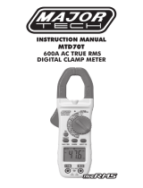
Extech Instruments MA150 is a versatile and feature-rich AC Mini Clamp Meter designed to provide accurate and reliable measurements for various electrical applications. With its compact size and easy-to-use interface, it's an ideal tool for electricians, technicians, and DIY enthusiasts. The MA150 measures AC current up to 200A, AC/DC voltage up to 600V, resistance up to 20MΩ, and features diode and continuity testing capabilities. Additionally, it includes a non-contact AC voltage detector for quick and safe voltage detection.

Extech Instruments MA150 is a versatile and feature-rich AC Mini Clamp Meter designed to provide accurate and reliable measurements for various electrical applications. With its compact size and easy-to-use interface, it's an ideal tool for electricians, technicians, and DIY enthusiasts. The MA150 measures AC current up to 200A, AC/DC voltage up to 600V, resistance up to 20MΩ, and features diode and continuity testing capabilities. Additionally, it includes a non-contact AC voltage detector for quick and safe voltage detection.

USER MANUAL
Model MA150
200A AC Mini Clamp-on Meter
AdditionalUserManualTranslationsavailableatwww.extech.com
MA150-en-GB_V2.4 1/17
2
Introduction
Thank you for selecting the Extech MA150 AC Mini Clamp Meter. This device is shipped fully tested
and calibrated and, with proper use, will provide years of reliable service. Please visit our website
(www.extech.com) to check for the latest version and translations of this User Manual, Product
Updates, Product Registration, and Customer Support.
Meter Description
1. Current sense jaw
2. Non-contact AC voltage indicator light
3. Flashlight button
4. Rotary function switch
5. MAX hold and Backlight key
6. LCD display
7. Clamp trigger
8. MODE key
9. COM input jack
10. V input jack
9
10
Safety Information
!
Caution! Refer to the explanation in this Manual
Double Insulation
This meter has been designed to be safe in use, but the operator must use caution in its operation.
The rules listed below should be carefully followed for safe operation.
1. NEVER apply voltage or current to the meter that exceeds the specified maximum:
2. USE EXTREME CAUTION when working with voltages greater than 60VDC or 25VAC rms.
These voltages are considerd a shock hazard.
3. NEVER operate the meter unless the back cover and the battery/fuse door are in place and
fastened securely.
Input Limits
Function Maximum Input
AC Current 200A
AC/DC Voltage 600V AC/DC
Resistance, Diode, Continuity Test 600V AC/DC
MA150-en-GB_V2.4 1/17
3
Operation
AC Current Measurements
1) Set the Function switch to the 200A AC range.
2) Press the jaw trigger and clamp around, fully enclosing a single conductor.
Do not allow a gap between the two halves of the jaw. Refer to the diagram
at right for the correct way to enclose a single conductor.
3) Read the ACA value on the LCD.
AC/DC Voltage Measurements
1) Insert the black test lead into the negative COM terminal and the red test lead into the positive V
terminal.
2) Set the function switch to the V position.
3) Select AC or DC with the MODE button.
4) Connect the test leads in parallel to the circuit under test.
5) Read the voltage measurement on the LCD display.
Resistance and Continuity Measurements
1) Insert the black test lead into the negative COM terminal and the red test lead into the positive V
terminal.
2) Set the function switch to the  position.
3) Use the MODE button to select resistance. The M icon will appear in the display.
4) Touch the test leads across the circuit or component under test. It is best to disconnect one side
of the device under test so the rest of the circuit will not interfere with the resistance reading.
5) For Resistance tests, read the resistance on the LCD display
6) For Continuity, use the MODE button to select continuity “)))”. The display icons will change
when the MODE button is pressed.
7) If the resistance is <120 the meter’s beeper will sound.
Diode Test
1) Insert the black test lead banana plug into the negative COM jack and the red test lead banana
plug into the positive V jack.
2) Set the function switch to the position.
3) Press the MODE button to indicate on the display.
4) Touch the test probes to the diode under test. Forward voltage will typically indicate 0.400 to
0.700V. Reverse voltage will indicate “OL”. Shorted devices will indicate near 0V and an open
device will indicate “OL” in both polarities.
Yes
No
MA150-en-GB_V2.4 1/17
4
Non-Contact AC Voltage Detection
1) AC Voltage detection operates on any of the three Function switch positions.
2) Touch the probe tip to the hot conductor or insert into the hot side of the electrical outlet.
3) If AC voltage is present, the detector light will illuminate.
NOTE: The conductors in electrical cord sets are often twisted. For best results, slowly slide the
probe tip along a length of the cord to assure placing the tip in close proximity to the live
conductor.
NOTE: The detector is designed with high sensitivity. Static electricity or other sources of energy
may randomly turn the detector light on. This is normal operation
MAX Hold
To hold the highest reading on the LCD, short press the “MAX
” key. The meter reading will not
change as readings change, rather it will only display the highest reading encountered since the MAX
hold button was pressed. Press the MAX hold button again to return the meter to normal operation.
Backlight
Press and hold the “MAX
” key for more than one second to turn the backlight on. This will also
activate the MAX Hold function. To release the MAX Hold function and return the meter to normal
operation, short press the “MAX
” key. The backlight will automatically turn off after 15 seconds. To
manually turn off the backlight, press and hold the “MAX
” key for more than 1 second.
Flashlight
Press and hold the top button to turn the flashlight on. Release the button to turn the flashlight off.
WARNING: Risk of Electrocution. Before use, always test the Voltage Detector on a
known live circuit to verify proper operation
MA150-en-GB_V2.4 1/17
5
Specifications
General Specifications
Display 2000 count Digit LCD with white LED backlight
Polarity Minus sign (-) indicates negative polarity
Jaw opening 18mm (0.7”)
Current sensor Hall effect sensor type
AC Current Bandwidth 50/60Hz
AC Voltage Bandwidth 50/400Hz
Overload indication “OL” displayed on the LCD
Display rate 2 readings/second, nominal
Battery Two 1.5V AAA batteries
Low Battery indication “BATT” displayed on the LCD
Auto Power off approx. 15 minutes
Operating conditions 0 to 30
º
C (32 to 86
º
F) 90%RH; 30 to 40
º
C (86 to 104
º
F) 75%RH; 40 to
50
º
C (104 to 122
º
F) 45%RH
Storage conditions -30 to 60
º
C (-14 to 140
º
F); < 90% Relative Humidity
Altitude Operate at less than 3000 meters
Weight 176g (6.2 oz.) including battery
Dimensions 164 x 65 x 32mm (6.5 x 2.6 x 1.3”) (HWD)
Standards For indoor use and in accordance with the requirements for double
insulation to IEC1010-1 (1995): EN61010-1 (1995) Overvoltage Category
III 300V and Category II 600V, Pollution Degree 2.
C
C
MA150-en-GB_V2.4 1/17
6
Range Specifications
Function Range Resolution Accuracy (of reading)
AC Current 200.0A 0.1A
± (2.5% rdg + 10 digits)
DC Voltage
200.0mV 0.1mV
±(0.5% rdg + 5 digits)
2.000V 1mV
±(1.2% rdg + 3 digits)
20.00V 10mV
200.0V 0.1V
600V 1V
±(1.5% rdg + 3 digits)
AC Voltage
2.000V 1mV
±(1.5% rdg + 3 digits)
20.00V 10mV
200.0V 0.1V
600V 1V
±(2.0% rdg + 4 digits)
Resistance
200.0 0.1
±(1.0% rdg + 4 digits)
2.000k 1
±(1.5% rdg + 2 digits)
20.00k 10
200.0k
100
2.000M 1k
±(2.0% rdg + 3 digits)
20.00M 10k
±(3.0% rdg + 5 digits)
Non-Contact AC Voltage 100VAC to 600VAC 50/60Hz
Diode Test
Test current: 0.3mA typical;
Open circuit voltage: 1.5VDC typical
Continuity
Threshold <120
Test current <1mA
MA150-en-GB_V2.4 1/17
7
Maintenance
WARNING:Toavoidelectricalshock,removethetestleads,disconnectthemeterfrom
anycircuitandturnOFFthemeterbeforeopeningthecase.Donotoperatewithanopencase.
Battery Replacement
1) When the low battery symbol appears on the LCD the batteries must be replaced.
2) Power down and remove the Phillips head screw that secures the battery compartment at the
back of the meter.
3) Open the battery compartment and replace the two 1.5V AAA batteries observing correct
polarity. Re-assemble the meter before use.
Safety: Please dispose of batteries responsibly; never dispose of batteries in a fire, batteries may
explode or leak. If the meter is not to be used for 60 days or more, remove the battery and store
separately.
Never dispose of used batteries or rechargeable batteries in household waste.
As consumers, users are legally required to take used batteries to appropriate collection
sites, the retail store where the batteries were purchased, or wherever batteries are sold.
Disposal: Do not dispose of this instrument in household waste. The user is obligated to take end-of-
life devices to a designated collection point for the disposal of electrical and electronic equipment.
Copyright©20132017FLIRSystems,Inc.
Allrightsreservedincludingtherightofreproductioninwholeorinpartinanyform
ISO9001Certified
www.extech.com
  • Page 1 1
  • Page 2 2
  • Page 3 3
  • Page 4 4
  • Page 5 5
  • Page 6 6
  • Page 7 7

Extech Instruments MA150 User manual

Category
Multimeters
Type
User manual

Extech Instruments MA150 is a versatile and feature-rich AC Mini Clamp Meter designed to provide accurate and reliable measurements for various electrical applications. With its compact size and easy-to-use interface, it's an ideal tool for electricians, technicians, and DIY enthusiasts. The MA150 measures AC current up to 200A, AC/DC voltage up to 600V, resistance up to 20MΩ, and features diode and continuity testing capabilities. Additionally, it includes a non-contact AC voltage detector for quick and safe voltage detection.

Ask a question and I''ll find the answer in the document

Finding information in a document is now easier with AI