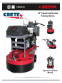
BETCO Crete Rx CP30 Owner's manual
- Category
- Floor Machine
- Type
- Owner's manual

1
E29800-00
30" Concrete and Terrazzo
Polishing Machine
Operator and Parts
Manual
400 Van Camp • Bowling Green, Ohio 43402
Customer Service: 888-GO-BETCO • Fax: 800-445-5056 • Technical Service: 877-856-5954 • www.betco.com

2
TABLE OF CONTENTS
RECEIVING THE MACHINE...............................................3
CARBON MONOXIDE WARNING ......................................4
SAFETY .......................................................................5 - 6
TANK USE AND STORAGE ...............................................6
UNPACKING THE MACHINE ............................................. 7
ENGINE PREPARATION AND OPERATION ..................8 - 9
MACHINE AND WORK AREA PREPARATIONS ...............10
TOOL DRIVE PLATE INSTALLATION ..............................11
MACHINE OPERATIONS .................................................12
TROUBLESHOOTING .....................................................13
FLOATING HEAD DECK ASSEMBLY ........................14 - 15
IDLER ASSEMBLY ................................................... 16 - 17
SOLUTION SYSTEM ................................................ 18 - 19
GEAR BOX ASSEMBLY ............................................ 20 - 21
ENGINE POWER SYSTEM .......................................22 - 23
ENGINE AND CARBURETOR ...................................24 - 25
EMISSION SHUT DOWN .........................................26 - 27
SOLUTION SWITCH ................................................28 - 29
ENGINE SHUT DOWN SWITCH ...............................30 - 31
FUEL REGULATION .................................................32 - 33
ENGINE SHUTDOWN WIRING .......................................34
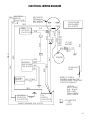
ELECTRICAL WIRING DIAGRAM ...................................35
EMISSIONS WARRANTY ........................................36 - 37
WARRANTY.................................................................... 40

3
RECEIVING THE MACHINE
Immediately check, when receiving the machine, that all the materials indicated on delivery documents have been
received and also that the machine has not been damaged in transit. If it has been damaged, this damage must be
immediately reported to the shipper and also to our customer service department or a claim may not be made.
Introduction
This machine is designed to work with BETCO’s Crete Rx
™
Concrete System. This floor machine Hones and Polishes
concrete and terrazzo floors through the action of its counter rotating deck and satellites, and the properly installed
BETCO Crete Rx Honing and Polishing tools.
Only use this machine for its intended purpose. Please keep the machine in good working order by performing routine
maintenance. Read this instruction manual and refer back to it when machine questions arise. The BETCO technical
customer service representatives should be contacted with machine questions not answered by this manual.
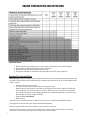
Technical Specifications
Working width in (mm) 30 (762)
Work productivity ft
2
/h (m
2
/h) 4,500 (418)
Run Time hours Up to 8
Deck Speed RPM 1040
Satellite Speed RPM 520 clockwise
Satellite Quantity - 3
Satellite Diameter in (mm) 13 (330)
Engine Capacity cu in (HP) 39.8 (22)
Propane Tank (D.O.T. 4E240) lbs 20
Battery Capacity volt 12
Solution tank capacity Gal (l) 11 (42)
Head Pressure (with empty solution tank) Lbs. (Kg) 615 (279)
Head Pressure (with full solution tank) Lbs. (Kg) 710 (322)
Weight of Empty Machine Lbs. (Kg) 950 (431)
Weight of Full Machine Lbs. (Kg) 1047 (475)
Machine dimensions, operating configuration in x in x in 73.5 x 50.0 x 30.0
(Length / Height / Width) (mm/mm/mm) (1887 / 1270 / 762)
Machine dimensions, stored configuration in x in x in 55.0 x 50.5 x 30.0
(Length / Height / Width) (mm/mm/mm) (1397 / 1283 / 762)
TECHNICAL DESCRIPTION Measurement Unit Crete Rx
™
CP30

4
Carbon Monoxide Poisoning Symptoms
Train your employees to know the warning signs of carbon monoxide poisoning.
Mild carbon monoxide poisoning may cause any of the following:
Headache, drowsiness, faintness, poor coordination, nausea, and vomiting.
Turn the engine off and immediately get to fresh air if you have any of these symptoms.
Do not run the machine until it is given an emissions test and repairs made by an authorized distributor.
• Local emissions testing is available at a fork-lift service department.
Moderate or severe carbon monoxide poisoning causes confusion, unconsciousness, chest pain, shortness of breath, and
coma. Thus, most victims are not able to move themselves and must be rescued. Severe poisoning is often fatal.
Carbon monoxide is dangerous because a person may not recognize drowsiness as a symptom of poisoning. Consequently,
someone with mild poisoning can go to sleep and continue to breathe the carbon monoxide until severe poisoning or death
occurs. Some people with long-standing, mild carbon monoxide poisoning caused by furnaces or
heaters may mistake their symptoms for other conditions, such as the flu or other viral infections.
Carbon Monoxide Detectors
CO detectors are a must for safe operation of your equipment. Various types are available. A “CO” carbon monoxide detector
detects carbon monoxide before it reaches dangerous levels. Detectors are a must for those who run propane powered
equipment. The CO Detector is for everyone’s protection against Carbon Monoxide Poisoning.
• Carbon Monoxide Detector - Passive
– Effective for 30 days after package has been opened.
– Write the date opened on the detector.
– Mount with self-adhesive strip on the machine handle.
– Train machine operator to check detector regularly.
– If the orange disk changes to gray or black - your Carbon Monoxide Levels are
at a Dangerous Level.
– If the orange disk changes to gray or black you must turn your buffer off immediately and return it to your nearest
authorized distributor for an emissions test.
– Do Not Restart the machine until the emissions have been checked and corrected.
– This is for your protection as well as your customers. CO detectors are a must for safe operation and maximum
efficiency of your equipment.
– For replacement CO detectors, contact your distributor. Ask for the carbon monoxide detector,
part# E012426.
• Carbon Monoxide Detector - battery operated with alarm
– Available from various sources
WARNING - CARBON MONOXIDE
LETHAL EXHAUST GAS
- MUST READ THIS! -
Never Run The Engine In A Closed Building Or Confined Area
Exhaust gases contain poisonous carbon monoxide.
Carbon monoxide is odorless, colorless, and can cause death if inhaled.

5
SAFETY
lmportant Safety Information
All LPG (Liquid Propane Gas) powered engines, including this engine, produce Carbon Monoxide (CO). It is a
Lethal Poison that is colorless, odorless, tasteless, and non-irritating gas. You must read “Danger: Lethal Exhaust Gas”
information below.
Keep hands, feet, and loose clothing away from all moving parts while the machine is in operation. The exhaust system
gets very hot so keep hands, clothing and any items that can burn away from the engine, engine manifold, and muffler.
These machines are tough and durable, however do not abuse the machine. With proper care and maintenance this unit
will give you years of trouble free operation.
Carbon Monoxide Safety Information
Engine exhaust gases contain poisonous carbon monoxide. Carbon monoxide is odorless, colorless, tasteless, and
can cause death if inhaled. Failure to provide proper venting of CO, failure to properly maintain the engine, or failure to
properly train personnel of the dangers and warning signs of carbon monoxide exposure may result in Serious Injury Or
Death to the operator and others in the area.
• Read the labels on the machine carefully. Do not cover the labels. Replace the labels if they become damaged.
• This propane floor machine must only be operated by authorized and trained professionals.
• The operator must wear the appropriate Personal Protective Equipment (gloves, shoes, helmet, glasses, etc.)
• When operating the machine do not endanger other people.
• Workers should be trained to recognize the hazards of carbon monoxide and the early symptoms of carbon
monoxide poisoning.
• Any equipment with the potential to produce carbon monoxide presents a significant hazard when used indoors.
They must be used with great caution. Opening a door or window, or running an exhaust fan will not necessarily
supply adequate ventilation. Avoid inhaling exhaust fumes and never run the engine in a closed building or
confined area without proper ventilation.
• Use only as described in this manual.
• Do not run the machine with the throttle in the choke position.
• Do not allow engine to run unattended.
• If you have any indication that the engine is not running properly, immediately shut the machine off. Perform
routine maintenance and if further service is required, contact your dealer or contact BETCO technical service.
• A carbon monoxide detector and alarm should be available to alert workers of emissions.
• Have a carbon monoxide detector attached to machine handle or have machine operator wear a carbon monoxide
detector. (See carbon monoxide detector page).
• Maintenance and repairs must be done by qualified personnel.
• When replacing parts, use only ORIGINAL replacement parts from your Authorized BETCO Dealer.
• If the machine is not working properly, have it serviced by a BETCO authorized service center.
• Have your BETCO service center perform routine maintenance on the machine once a year.
• Install fuel cylinder in a well ventilated place.
• Be aware of possible leaks of propane gas if odor is present.
• If the machine is stored inside a building, remove the fuel cylinder and store properly outside.
• Secure fuel cylinders when being transported.
• If tank is left attached to the machine then valve should be OFF.
• Never store fuel cylinders in a vehicle, building, or area where they may exposed to high temperature.
• Do not operate the machine with any openings blocked.
• Keep openings free of debris that may reduce airflow.
• Remove fuel cylinder and disconnect battery before servicing.
(list continued on next page)

6
SAFETY (continued)
• Do not place objects on the machine.
• Never use the machine in an explosive environment.
• Do not use the machine as a means of transportation.
• Use a dry powder fire extinguisher in case of fire or use water.
• Do not strike shelving or scaffolding.
• Never remove guards that require tools to remove.
• When your BETCO machine is ready to be disposed of, the machine must be disposed of properly. It contains
oils and electronic components. The machine itself was built using totally recyclable materials.
• Use only tools furnished with the machine or those specified in the user's manual.
Silica Dust and the Use of a Respirator
Silica is a sand component of concrete and its dust can cause severe medical conditions, such as; Silicosis, Lung
Cancer, Tuberculosis, Autoimmune and Chronic Kidney Diseases and non-malignant respiratory diseases. BETCO
highly recommends the use of a respirator during concrete honing and polishing. For more information on Silica safe
handling, storage and safety measures visit www.u-s-silica.com or call 1-800-35-NIOSH.
TANK USE AND STORAGE
Propane Tank Use
We use the Worthington gas cylinders designed for vapor withdrawal. The fuel lock offs, regulators, and engines are
also designed for vapor withdrawal.
• We recommend that you use the OPD (Overflow Protection Device) vapor withdrawal type cylinder. These style
tanks have a triangle shaped valve handle.
• Do not overfill - the best gauge is a scale - never allow tank to weigh over 36 pounds for an aluminum tank and
43 pounds for a steel tank.
• Connect fuel cylinder to machine in a well ventilated place.
• Be aware of possible leaks of propane gas if odor is present.
• Use propane tanks designed for vertical use only.
• New tanks must be purged of air at first filling.
Propane Tank Storage
• Store tanks outside in a well-ventilated area.
• Never store fuel cylinders in a vehicle, building, or area where they may exposed to high temperature.
• If the machine is stored inside a building, remove the fuel cylinder and store properly outside.
• Secure fuel cylinders when being transported.
• If tank is left attached to the machine then valve should be OFF.
• Store tanks in the upright position (valves up).
• Be aware of possible leaks of propane gas if odor is present.

7
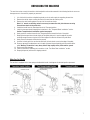
UNPACKING THE MACHINE
This machine arrives securely fastened to a reinforced pallet and must be removed in the following fashion to ensure no
damage occurs to the machine, property or personnel.
1. It is vital that this machine and pallet be placed on a level surface prior to unpacking the machine.
2. Remove the ratchet straps securing the front of the machines deck to the pallet.
3. Remove the steel fastening plates from each of the machines wheels.
Note: A ¾” wrench or ratcheting socket is necessary to remove the steel plate fasteners securing
the machines wheels to the pallet deck.
4. Unfold the handle from the Stored position to the Transport position.
5. Install the transport wheel following the instructions in the “Transport Wheel Installation” section.
Caution: Transport wheel installation requires two people!
6. Slowly push the machine forward in the Transport position towards the front of the pallet.
7. Keeping the transport wheel raised slightly off the pallet deck push it past the edge of the pallet
ensuring enough clearance is given for the front edge of the deck to not touch the pallet deck.
8. Slowly lower the transport wheel onto the ground.
9. Continue to slowly push the machine forward until the back wheels come to the edge of the pallet.
10. Ensure no personnel or obstructions are in the path of the machine and carefully push the machine off the
pallet. Warning: The machine is very heavy and will drop rapidly off the pallet onto the ground.
11. Check machine for damage.
12. Install the tool drivers following the instructions in the “Tool Drive Plate Installation” section.
13. Properly dispose of pallet and all shipping material.
Adjusting the Handle
The machine is equipped with a telescoping and adjustable handle. See diagrams for detailed position placement.

8
ENGINE PREPARATION AND OPERATION
IMPORTANT NOTES:
1. Before performing any maintenance, turn off the engine and disconnect the fuel tank and battery.
2. Change engine oil and oil filter after first 8 hours of operation.
3. Maintenance should be done by qualified personnel only.
4. Change foam and paper air intake filters and spark plugs after first 25 hours of operation.
Checking Oil Levels and Filters
Check Oil Level: Starting the engine without the proper amount of oil will cause severe engine damage. Always keep
the engine oil level between the full and add marks on the dipstick. Do not loosen oil fill cap or remove dipstick while
engine is running.
• Park your machine on a level surface.
• Turn the oil fill cap counter clockwise and then lift from the fill tube.
• Wipe the dip stick clean and push it back into the oil fill tube until the cap seats and then withdraw it to
check: the oil level. (Do not screw cap on to check oil). Add if necessary. If the oil level is low, add API
Class SM oil having a SAE viscosity grade appropriate for the expected temperatures as indicated in the
Operators Manual (Usually a HD30 or 10W30).
• Important Note: Do Not Overfill
• Replace oil cap.
Inspect fuel hoses and fittings for wear and leaks. Have all worn hoses and leaks repaired before operating.
Look and listen for exhaust leaks. Have all leaks repaired before operating.
Check the carburetor filter and air filter for debris. Clean and replace if necessary.
Connect fuel hose to tank by screwing the hose fitting to tank. You must tighten all the way down to make fuel
connection. Turn tank knob slowly until you hear the flow of fuel into fuel system.

9
ENGINE PREPARATION AND OPERATION (continued)
Installing the Propane Cylinder
1. Take machine to a well ventilated area.
2. Check cylinder for overfill.
3. Place cylinder on the machine in tank holding area and secure strap.
4. Attach the propane hose coupling and fully tighten.
5. Open service valve slowly. Be alert for the odor of propane that may indicate a leak.
6. To remove the cylinder, reverse the procedure.
Starting the Engine
Before starting the engine, read the Owner's Manual and the Engine Operation Manual.
The engine is equipped with a 12 volt starter and a key switch start.
1. Install the propane cylinder following the instructions in the “Installing the Propane Cylinder” section
Warning: Start the machine with the floor tools in the running position, flat on the floor.
2. Pull the choke lever to the choke position and then turn the ignition - key switch to the 'start' position
and hold it there until the engine starts.
Caution: Do not crank for more than 20 seconds at a time and wait at least one minute between tries
when cranking. See the troubleshooting guide if the engine does not start after several tries.
3. After engine starts, depress the choke lever to the off position and then set the throttle so that the
centrifugal clutch will not engage until the engine has warmed up (less than 1500 RPM). Do not operate
the machine until the engine has warmed up sufficiently (3 to 5 minutes).
4. Check for frost on the regulator and fuel line. Frost will indicate that the machine is drawing liquid
propane from an overfilled or incorrect tank.
Warning: Do not run engine with throttle in the choke position! Excessive harmful emissions will be produced.
Personal harm or engine damage may occur.
Stopping the Engine
1. Set the throttle to the lowest position.
2. Turn propane tank valve to the closed position (turn clockwise) and allow the engine to continue
running until it runs out of fuel.
3. Turn key to the off position.
In an emergency, immediately press and hold the kill switch and turn the key to the 'off' position. Backfiring
may occur when using this method.

10
MACHINE AND WORK AREA PREPARATIONS
Caution: Before performing any maintenance or machine preparation, turn off the engine and disconnect the fuel
tank and battery.
If using the solution tank to dispense liquid on the floor, fill the tank with the desired chemical to be used.
Perform all engine and machine checks and maintenance as needed.
Transport Wheel Installation
Caution: Do not install the transport wheel with the engine running.
Warning: Transport Wheel Installation Requires two people!
To install the Transport Wheel Support Arm follow these steps:
1. Extend the handle to the Tool Change Position. Press downward on the handle bar until the back of
machine rests on the ground.
2. While holding the handle down, have an assistant release the locking pin on the Transport Receiver and
slide the Transport Wheel Support Arm into the Transport Receiver.
3. Slowly lower the machine back onto the level surface.
4. Collapse the handle back into the Transport Position.
Transport Wheel Removal
Caution: The transport wheel must be removed before starting the engine.
Warning: Transport Wheel Removal Requires two people!
To remove the Transport Wheel Support Arm follow these steps:
1. Extend the handle to the Tool Change Position. Press downward on the handle bar until the back of
machine rests on the ground.
2. While holding the handle down, have an assistant release the locking pin on the Transport Receiver and
remove the Transport Wheel Support Arm.
3. Slowly lower the machine back onto the level surface.
4. Collapse the handle back into the Operating Position.

11
TOOL DRIVE PLATE INSTALLATION
Betco Crete Rx Honing & Polishing Tool Installation
The drive plates provided with this machine are specifically designed for the BETCO
®
Crete Rx
™
Concrete Floor
System. These instructions are based on the use of this system.
With the transport wheel installed:
1. Check the drive plate and tool holders to ensure they are properly installed.
2. Check the Velcro on both the tool holder and tools to be installed.
3. Install the tools by firmly pressing a single tool into each of the tool holders and slightly twisting to
ensure the Velcro properly adheres.
Area Preparation
This floor machine is designed to be used only on concrete and terrazzo floors. Use on any other surface may cause
personal harm, damage to property, or damage to the machine. Work areas should be prepared following these
steps:
1. Ensure that the area is free of objects protruding from the floor and loose pieces of flooring.
2. The area to be worked on should allow adequate room for machine operation.
3. Proper ventilation must be used to prevent harmful gases from building up.
4. Do not use the machine in a work area where others are present and may be harmed.
5. Clean the floor of any loose debris and dirt.

12
MACHINE OPERATIONS
Caution: Never tip the machine back while the engine is running.
Honing Process
1. Ensure work area is a level surface and free from loose debris.
2. Start the engine following the instructions in the “Starting the Engine” section.
3. Increase the engine throttle to 3150 RPM.
4. Slowly walk forward as the deck and satellites spin up to full speed.
5. Utilize the solution on/off switch to adequately soak the work area with BETCO Liquigrind solution.
6. Progress through the work area at 30 ft/min using the BETCO
®
Crete Rx
™
Honing Tool.
7. Ensure to overlap each pass by at least 1/3 of the deck’s width.
8. Multiple passes over the working area may be required.
9. Stop the engine following the instructions in the “Stopping the Engine” section.
10. Ensure the solution tank valve is fully closed.
11. Follow the Honing process with proper slurry removal steps.
Polishing Process
1. Ensure work area is a level surface and free from loose debris.
2. Start the engine following the instructions in the “Starting the Engine” section.
3. Increase the engine throttle to 3150 RPM.
4. Slowly walk forward as the deck and satellites spin up to full speed.
5. Progress through the work area at 30 ft/min using the BETCO Crete Rx Polishing Tool.
Note: The Betco Crete Rx Polishing step is performed dry with no solution on the work area.
6. Ensure to overlap each pass by at least 1/3 of the deck’s width.
7. Multiple passes over the working area may be required.
8. Stop the engine following the instructions in the “Stopping the Engine” section.
9. Follow the Polishing process with proper dust removal steps.

13
TROUBLESHOOTING
PROBLEM CAUSE POSSIBLE SOLUTION
Engine will not turn over
Battery is dead
Recharge battery or replace
if necessary
Loose wire or bad connection Check wires and connections
Bad electrical component Replace bad component
Fuel system problem
Refer to engine owner’s manual
and read IMPORTANT below
Engine turns over, but will not start
Propane tank shut off valve in
off position
Open propane tank shut off
valve completely
Low oil Add oil
Fuel system problem
Refer to engine owner’s manual
and read IMPORTANT below
Propane tank empty Fill propane tank
Engine problem
Refer to engine owner’s manual
and read IMPORTANT below
Hard to start
Throttle lever in slow position Push throttle lever to fast position
Propane tank shut off valve not
fully open
Open propane tank shut off
valve completely
Some type of engine problem
Refer to engine owner’s manual
and read IMPORTANT below
Engine stops suddenly and will
not restart
Out of propane
Replace propane tank with
full propane tank
Low oil Add oil
Engine overheats
Intake air filter is dirty Remove air intake filter and clean
Incorrect oil level
Add or remove oil to achieve
proper oil level
Lacks power Some type of engine problem
Refer to engine owner’s manual
and read IMPORTANT below
Engine stops and will restart, but
stops again
Emission shut-down
system engaged
Refer to engine owner’s manual
and read IMPORTANT below
Nothing here fixes the problem Problem could have several causes Read IMPORTANT below
Excessive vibration
Loose bolts on engine or deck Inspect and tighten all bolts
Improperly installed tools
With help, check and reinstall
tools if needed.
Incorrect oil level
Add or remove oil to achieve
proper oil level
Engine overloaded
See engine owner’s manual
for servicing
Some type of engine problem
Refer to engine owner’s manual
and read IMPORTANT below
IMPORTANT: Propane fueled combustion engines produce dangerous gases and must be serviced by authorized
service personnel trained specifically to service propane fueled engines and fuel systems. The troubleshooting
tips are not intended to take the place of authorized service personnel. If you are unsure of what to do contact an
authorized service personnel. Before working on this machine you must be familiar with the safety instructions in
this manual.

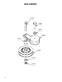
14
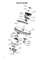
FLOATING HEAD DECK ASSEMBLY
E13114
E13128
E13014
E13038
E13174
E13039 E13173
E13159
E10135
E13037
E13021
E13013
E13009
E13012
E13006
E13160
E81713
E13053
E13104
E13135
E81062
E13085
E10135
E13036
E13016
E13002
E13155
E13138
E10135
E13037
E13032
E13026
E13020
E13026
E13028
E13029
E13164
E13163E13149
E13142
E81713
E13053
E13024
E13022
E13023
E13172
E13029
E13015
E13000
E13028
E13026
E13001
E13036
E13008
E10135
E13037
E10135
E13007
E13134
E13033
E13003
E13005
E13026
E13029
E13010
E13060
E13034
E13035 E13166
E13019
E13004
E13015

15
FLOATING HEAD DECK ASSEMBLY PARTS LISTING
E10135 Washer, Flat, 3/8" 24
E13000 Frame, Engine Platform 1
E13001 Bracket, Transport Arm 1
E13002 Handle Assembly 1
E13003 Axle, Main Wheel, 13" 2
E13004 Pin, Cotter 2
E13005 T-Nut, 5/8"-11 Coarse" 4
E13006 Pin, Handle 2
E13007 Wheel, Transport 1
E13008 Transport Wheel Support Arm 1
E13009 Choke Cable, Push/Pull 1
E13010 Wheel Assembly, 10" x 2" 2
E13012 Switch, Key 1
E13013 Key (1) 1
E13014 Handle Grip 2
E13015 Pin, Quick Disconnect 2
E13016 Cap, Flexible Push On 1
E13019 Spacer, Wheel, 5/8" 2
E13020 Arm, Pivot 2
E13021 Battery Box, Metal 1
E13022 Pin, Pivot 2
E13023 E-Clip 4
E13024 Fitting, Grease 2
E13026 Washer, Flat, 5/8" SAE 14
E13028 Washer, Split Lock, 5/8" 8
E13029 Screw, Hex Cap, 5/8"-11 x 2", SS GR8 12
E13032 Screw, Hex Cap, 5/8"-11 x 6" Tap, SS GR8 2
E13033 Spacer, 1/2" x 5/8" 2
E13034 Washer, Flat, 1" SAE 2
E13035 Nut, Hex, 1"-14, Slotted 2
E13036 Screw, Hex Cap, 3/8"-16 x 1-1/4" 10
E13037 Nut, Nyloc, 3/8"-16 12
E13038 Throttle 1
E13039 Hour Meter, Mini Tach 1
E13053 Nut, Nyloc, 1/4"-20 3
E13060 Bearing, Wheel 4
E13085 Washer, Split Lock, 5/16", Zinc 4
E13104 Wiring Harness 1
E13114 Switch, Engine Shut Off, (Switch Only) 1
E13128 Switch, Solution On/Off, (Switch Only) 1
E13134 Splash Guard 1
E13135 Tank Latch 1
E13138 Tape, Velcro 4
E13142 Arm Support 2
E13149 Screw, Socket Head Button, 1/4"-20 x 1" 2
E13155 Screw, Hex Cap, 5/16"-18 x 1" 4
E13159 Screw, Socket Head Button, 3/8"-16 x 1 2
E13160 Screw, Hex Head, 1/4"-20 x 5-1/2" 1
E13163 Screw, Socket Head Cap, 7/16"-14 x 1-3/4" 4
E13164 Cover, Front Pulley 1
E13166 Spacer, Wheel, 1/2" 2
E13172 Dome Plug 1
E13173 Nut, Hex, 6-32 2
E13174 Screw, Round Combo Head, 6-32 x 2-1/2" 2
E81062 Washer, Flat, 5/16" USS 4
E81713 Washer, Flat, 1/4" 4
Part# Description Qty. Part# Description Qty.

16
IDLER ASSEMBLY
E13043
E13025
E88673
E13040
E13041
E13042
E10135
E13037

17
IDLER ASSEMBLY PARTS LISTING
E10135 Washer, Flat, 3/8" 1
E13025 Screw, Hex Cap, 3/8"-16 x 1" 1
E13037 Nut, Nyloc, 3/8"-16 1
E13040 Arm, Tensioner 1
E13041 Bushing, Shoulder, 3/4" 1
E13042 Pulley, Idler 1
E13043 Screw, Hex Cap, 3/8"-16 x 2-1/2" 1
E88673 Washer, Fender, 3/8" ID, 1-1/4" 1
Part# Description Qty. Part# Description Qty.

18
E13050
E13049
E13055
E13052
E13054
E13052
E13130
E13055
E13174
E13173
E13161
E13048
E13047
E13046
E13044
E13045
E13161
E13139
E10135
E13018
E13162
E13051
E13036
E10135
E13037
E10135
E13053
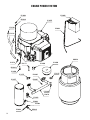
DECAL
ADDITIONAL HOSE CLAMPS
E13161 (x3) REQUIRED
SOLUTION SYSTEM

19
SOLUTION SYSTEM PARTS LISTING
E10135 Washer, Flat, 3/8" 12
E13018 Washer, Split Lock, 3/8" 4
E13036 Screw, Hex Cap, 3/8"-16 x 1-1/4" 4
E13037 Nut, Nyloc, 3/8"-16 4
E13044 Nipple, 1/2" Pipe x 1-1/4" 1
E13045 Elbow, Female and Male, 1/2" NPT, PVC 1
E13046 Coupling, 1/2" PVC 1
E13047 Coupling, Female, Quick 1
E13048 Coupling, Male, Quick 1
E13049 Tank, Solution 1
E13050 Cap Assembly, Solution Tank 1
E13051 Bracket, Solution Tank 1
E13052 Fitting, Male Thread, 1/2" Barb 2
E13053 Decal 1
E13054 Valve, Ball, 1/2" 1
E13055 Hose, 1/2" Flexible 1
E13130 Solenoid, Solution, 12V 1
E13139 Fitting, Female Thread, 1/2" Barb 1
E13161 Hose Clamp 6
E13162 Screw, Hex Head, 3/8"-16 x 3/4" 4
E13173 Nut, Hex, 6-32 2
E13174 Screw, Round Combo Head, 6-32 x 2-1/2" 2
Part# Description Qty. Part# Description Qty.

20
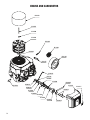
GEAR BOX ASSEMBLY
E13056
E13057
E13058
E13157
E13140
E13028
E13026
E13140
E13061
E13141
E13063
E13064
E13146
E12407
E13067
E13149
E13069
E13037
E13066
E13081
E13165
E13025
E13070
E13064
E13133
E13073
E10135
E13143
Page is loading ...
Page is loading ...
Page is loading ...
Page is loading ...
Page is loading ...
Page is loading ...
Page is loading ...
Page is loading ...
Page is loading ...
Page is loading ...
Page is loading ...
Page is loading ...
Page is loading ...
Page is loading ...
Page is loading ...
Page is loading ...
Page is loading ...
Page is loading ...
Page is loading ...
Page is loading ...
-
 1
1
-
 2
2
-
 3
3
-
 4
4
-
 5
5
-
 6
6
-
 7
7
-
 8
8
-
 9
9
-
 10
10
-
 11
11
-
 12
12
-
 13
13
-
 14
14
-
 15
15
-
 16
16
-
 17
17
-
 18
18
-
 19
19
-
 20
20
-
 21
21
-
 22
22
-
 23
23
-
 24
24
-
 25
25
-
 26
26
-
 27
27
-
 28
28
-
 29
29
-
 30
30
-
 31
31
-
 32
32
-
 33
33
-
 34
34
-
 35
35
-
 36
36
-
 37
37
-
 38
38
-
 39
39
-
 40
40


BETCO Crete Rx CP30 Owner's manual
- Category
- Floor Machine
- Type
- Owner's manual
Ask a question and I''ll find the answer in the document
Finding information in a document is now easier with AI
Related papers
-
BETCO Crete Rx CM30 Owner's manual
-
-
-
-
-
-
-
-
-
Other documents
-
Hay TERRAZZO TABLE User manual
-
Minuteman Propane Burnisher User manual
-
 Colour Crete 59101 User manual
-
Powr-Flite PB211, PB2111C, PB2413, Owner's manual
-
Onyx S7PAMN User manual
-
Windsor Lightning BDP Propane Burnisher Owner's manual
-
Eagle 680022 User manual
-
 Amano Pioneer Eclipse SAFR PE440BU User manual
-
National 5600 User manual
-

