it disappear in its drill hole and reveal the hole. If it doesn‘t, carefully
loosen the counterweight screw until the bolt moves. Remove the safety
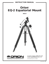
cover (23, illustration 1d) from the rod. Hold the counterweight firmly
whilst moving it to about the middle of the counterweight rod (22, illustra-
tion 1d). Tighten the counterweight fastening screw and then replace the
safety cover.
NOTE:
If the counterweight ever slips, the safety cap (23, Fig. 1d) prevents the counter-
weight from sliding entirely off the shaft. Always leave the safety cap in place when
the counterweight is on the shaft.
6. Set the latitude. Setting the latitude is easier if it is set before you attach the
optical tube to the assembly. Locate the latitude dial (28, Fig. 1d); note that
there is a triangular pointer above the dial located on the mount. The pointer
is not fixed; it moves as the mount moves.
Determine the latitude of your observing location. See APPENDIX B:
LATITUDE CHART, page 28-29, for a list of latitudes, or check an atlas. Move
the latitude T-handle screws in order to move the mount until the pointer
points to your latitude. The two T-handle screws (EXOS-2 only) work in a
„push - pull“ operation—as you tighten one, loosen the other. When the point
-
er points at your latitude, tighten both screws until they make contact with the
mount. The EXOS-1 has on screw with similar operation.
At your observing site, set up the telescope assembly so that this leg approxi-
mately faces North (or South in the Southern Hemisphere).
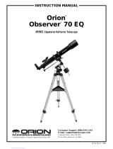
7. Attach the cradle assembly to the mount – Models R and N: Remove the opti
-
cal tube from the cradle and slide the cradle assembly (11, Fig. 1a) onto the
cradle mounting slot. See Fig. 7. The rounded base of the cradle assembly fits
into the rounded portion of the mounting slot. Tighten both the cradle locking
knob and the secondary locking knob to a firm feel.
8. Position optical tube – Models AR and NT: Unscrew the cradle ring lock
knobs (13, Fig. 1a) and open the cradle rings. While firmly holding the optical
tube (10, Fig. 1a), position it onto the cradle rings (14, Fig. 1a) with the mid-
point of the optical tube’s length lying roughly in the center of the cradle ring
assembly. Point the tube so that the front end (this end comes shipped with
the dust cover (9, Fig. 1a) over it) is oriented as depicted in Fig. 1a. Then
close the cradle rings (14, Fig. 1a) over the optical tube. Loosely tighten the
cradle ring lock knobs just to hold the tube securely in place until you bal
-
ance it. See Balancing the telescope, page 13.
9.
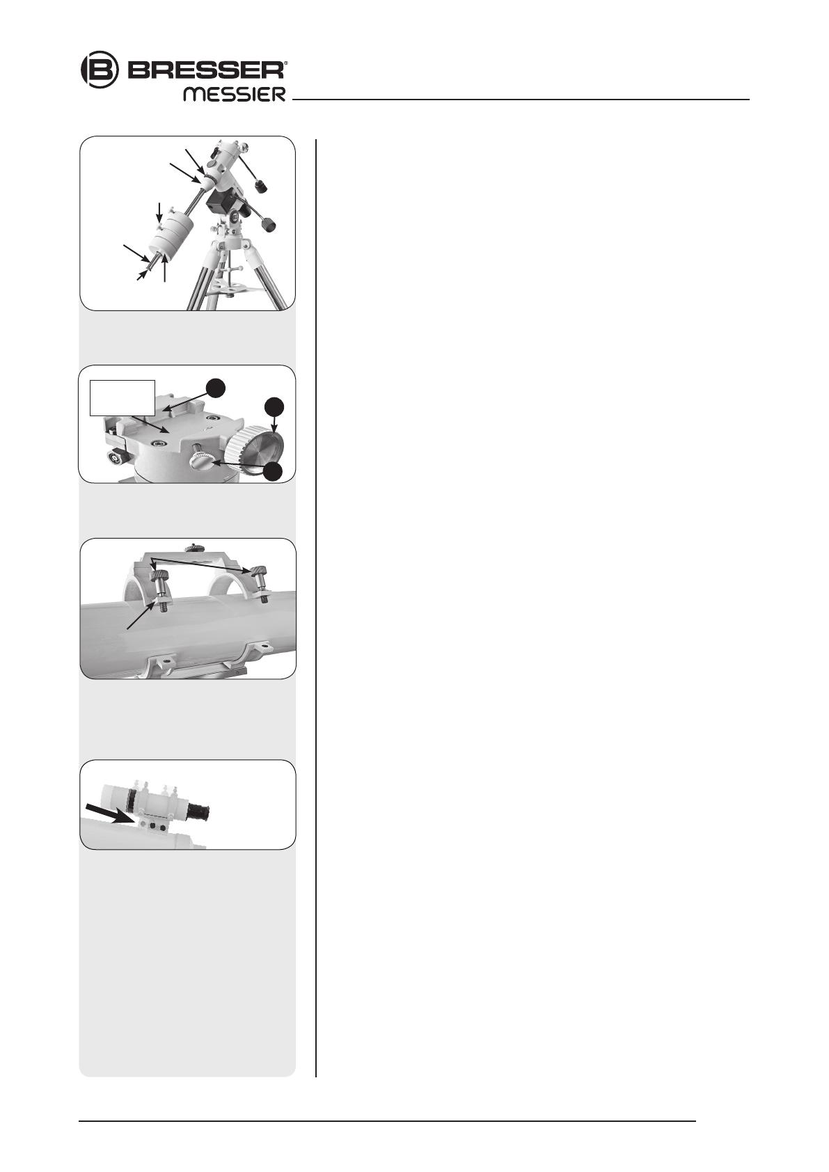
Attach viewfinder bracket
(Abb. 9b). Locate the viewfinder bracket screws
(15, Fig. 1b and Fig. 9a) and remove the nuts from the screws. Slide
the holes in the viewfinder bracket over the viewfinder bracket screws.
Replace the nuts and tighten to a firm feel only.
9a. Attach viewfinder tube:. Back off the viewfinder collimation screws (5,
Fig. 1b) and slide the viewfinder tube into the bracket. Orient the view-
finder eyepiece as depicted in Fig. 1b. Tighten the collimation screws to
a firm feel. See Aligning the viewfinder, page 14.
10. Insert the eyepiece: NT models (Fig. 10a): Lift to remove the dust cap
from the eyepiece holder on the focuser assembly. Set the dust cap
aside in a safe place and replace it when you have finished observing
to protect the eyepiece assembly. Back off the eyepiece thumbscrews
(1, Fig. 1a) and insert the supplied 25mm eyepiece (3, Fig. 1a) into the
the eyepiece holder. Tighten the holder thumbscrews to a firm feel to
secure the eyepiece. AR models (Abb. 10b): Lift to remove the dust cap
from the eyepiece holder on the focuser assembly. Set the dust cap
aside in a safe place and replace it when you have finished observing
to protect the eyepiece assembly. Back off the eyepiece thumbscrews
(1, Fig. 1b) and slide the diagonal prism into the holder and tighten the
thumbscrews to a firm feel only. Insert the supplied 25mm eyepiece (3,
Fig. 1b) into the the diagonal prism. Tighten the prism‘s thumbscrews to
a firm feel to secure the eyepiece.
Looking at or near the Sun will cause instant and irreversible damage to your eye!
12
assemblInG exos-2
Fig. 8a: Place the optical tube
in rings and loosely tighten the
cradle ring lock knobs.
Cradle rings
Lock
knobs
Fig. 9b: Viewfinder assembly.
Slide bracket into slot.
Fig. 6a: Attach counterweight
assembly (EXOS-1)
Fig. 7: Mounting the cradle assembly
to the mount shaft (EXOS-2)
Cradle
assembly set
A
B
C
Safety cap
Counter-
weight
shaft
Counterweight
locking knob
Counter-
weight
Shaft base
DEC-setting circle