Page is loading ...

L8542644
12/2011 rev 4
UNIONE NAZIONALE COSTRUTTORI
AUTOMATISMI PER CANCELLI, PORTE
SERRANDE ED AFFINI
CORE

2
DL1
DL2
N
G N D
L
LAMP 115/230Vac
40W max
COM
M
C
SCA
24Vac
3W max
24Vac
200mA max
P.P.
STOP
SWO
SWC
PHOT
COM
P1 P2
SW
1 6
TW
ENC1
TCA
ANT
SHIELD
ANT
U2
F3
F2
F3 CORE 230: F6,3A
F3 CORE 115: F10A
F2: F315 mA
1

8
EC declaration of confirmity
Manufacturer: Automatismi Benincà SpA.
Address: Via Capitello, 45 - 36066 Sandrigo (VI) - Italia
Herewith declares that: control unit CORE.
complies with the following relevant provisions:
EMC guidelines: 89/336/CCE, 93/68/CEE
Low voltage guidelines: 73/23/CEE, 93/68/CEE
Benincà Luigi, Legal responsible.
Sandrigo, 10/11/2011.
SPECIFICATIONS
Mains power supply
230 VAC 50/60 Hz (115 VAC 50/60Hz CORE 115)
Output, Motor
1 motor, 230 VAC (115VAC CORE 115)
Motor maximum power
750 W
Output, power supply of accessories
24VDC 200mA max.
Protection level
Version in LB box: IP55 – BULL version: IP30
Operating temperature
-20°C / +70°C
Radio receiver
433.92 MHz, incorporated and configurable
(rolling-code or fixed+rolling-code+ ARC Advanced Rolling Code)
No. of codes storable in memory
64
WARNINGS
This manual has been especially written to be use by quali-
fied fitters.
None of the information provide in this manual can be con-
sidered as being of interest for the end users.
Preserve this manual for future needs.
The technician has to furnish all the information related to the
step by step function, the manual and the emergency function
of the operator, and to deliver the manual to the final user.
;
Foresee on the supply net an onnipolar switch or
selector with distance of the contacts equal or
superior to 3 mms.
Verify that of the electrical system there is an awry differential
interrupter and overcurrent protection.
Some typologies of installation require the connection of the
shutter to be link at a conductive mass of the ground accord-
ing to the regulations in force.
The electrical installation and the operating logic must comply
with the regulations in force.
The leads fed with different voltages must be physically
separate, or they must be suitably insulated with additional
insulation of at least 1 mm.
The leads must be secured with an additional fixture near
the terminals.
During installation, maintenance and repair, interrupt the
power supply before opening the lid to access the electri-
cal parts
Check all the connections again before switching on the
power.
The unused N.C. inputs must be bridged.
The descriptions and the present illustrations in this manual
are not binding. Leaving the essential characteristics of the
product unchanged, the manufacturer reserves himself the
right to bring any change of technical, constructive or com-
mercial character without undertaking himself to update the
present publication.

9
CONTROL PANEL CORE
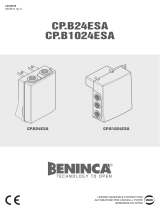
WIRE DIAGRAM
Wire connections shown in Fig. 1 are described hereunder:
Terminals Function Description
L-N-GND Power supply
Input, 230VAC 50Hz (CORE)
Input, 115VAC 50/60Hz (CORE 115V))
(1-Phase/2-Neutral/GND-Ground connection)
MOT-COM-MOT Motor
Connection to motor:
(MOT-move/COM-Common/MOT-move)
N-BLINK LAMP
Output, connection to Flashing light
CORE: 230 Vac 40W max.
CORE 115V: 115 Vac 40W max.
SWO SWO Input, OPENING limit switch (Normally Closed contact)
SWC SWC Input, CLOSING limit switch (Normally Closed contact)
PHOT (CLOSE) PHOT
Input, connection to safety devices, Normally Closed (N.C.) contact
(e.g. photocells): configurable through DIP3).
In “Service man” mode, it activates the CLOSE function. In this
case connect a Normally Open (N.O.) key.
STOP STOP Input, STOP key (N.C. contact)
COM COM Common, all control inputs.
P.P. (OPEN) Step-by-Step
Input, step-by-step key (N.O. contact).
In “Service man” mode, it activates the OPEN control function.
24 VAC 24Vac Output, 24Vac/200mA max accessory power supply.
SCA SCA
Contact free from voltage, not insulated for the connection of open
gate indicator lamp.
Open contact with closed door leaf. Flashing light during the door
leaf movement. With open door leaf, the contact is closed.
ENC1 ENCODER
Input, connection of the encoder.
See section HOW TO ADJUST BRAKING
SHIELD-ANT Antenna
Connection of the antenna to the incorporated radio-receiver module
(SHIELD-screen/ANT-signal).
Note:
The control unit uses a “P2” key with the same functions of the Step-by-Step push-button. This is useful
to control the automatic system during installation (only with DIP2: OFF).
CHECKING CONNECTIONS:
1) Cut off power supply.
2) Manually release the door, move it at around half stroke and lock it again.
3) Reset power supply.
4) Send the step-by-step (P.P.) control signal through the P2 key, P.P. or remote control.
5) The door leaves should open. If not, with stopped motor, it is sufficient to invert the move wires of the
motor (MOT/MOT) of the motor and the limit switches (SWO/SWC).
6) Adjust Times and operating Logics.

10
TRIMMER FUNCTIONS
TW It allows the maximum duration of opening and closing.
It must be preset approx. 4s more with respect to the actual stroke time of the system.
The adjustment ranges from 3s to 180s maximum.
If installed, the Encoder provides the function of anti-crash sensitivity adjustment.
TCA It allows to adjust the automatic closure time.
The adjustment ranges from 3s to 180s maximum.
With TCA trimmer completely turned clockwise, the DL2 LED (green) switches off, TCA is
deactivated.
DIP-SWITCH FUNCTION
Dip-Switches Function Description
DIP1
Set-up
To be used only for the setting-up of the torque and the forewar-
ning and braking time.
After moving DIP1 to ON:
- with P1 push-button the torque is adjusted.
- with push-button P2 the forewarning light is activated/deactiva-
ted.
- with the Step-by-Step input or a memorised remote control,
braking length is adjusted (with Encoder only).
See the related sections.
After presetting the parameters, move to OFF.
DIP2 Multi-flat
The multi-flat function is enabled or disabled.
Off: disabled multi-flat function.
On: enabled multi-flat function.
The P.P. (Step-by-step) impulse or the impulse of the transmitter
have no effect in the opening phase.
DIP3
PHOT: operating
mode
The operating mode of the PHOT input is selected
Off: Input, activated in both opening and closing phases
On: Input, activated in the closing phase only
DIP4
P.P.: operating
mode
The operating mode of the “P.P. push-button” and the transmitter
are selected.
Off: Operation: OPEN > STOP > CLOSE > STOP >
On: Operation: OPEN > CLOSE > OPEN >
DIP5 Rapid closure
The rapid closure is enabled or disabled with (only with activated
TCA)
Off: disabled rapid closure
On: enabled rapid closure. The triggering of the photocell involves,
after approx. 3s, the closure of the door.
DIP6 Radio
The programmable code transmitters are enabled or disabled.
On: Radio receiver is enabled for roll-on code transmitters only.
Off: Receiver is enabled for both roll-on and programmable code
transmitters.
HOW TO ADJUST BRAING (WITH ENCODER ONLY)
To adjust braking length in both opening and closing phases, proceed as follows:
1) Close the gate (make sure that the closing limit switch is pressed).
2) Move DIP 1 to ON
3) Send PP control signal (through Step-by-Step Input or memorised remote control). The gate starts opening
at normal speed.

11
4) When the gate reaches the desired braking point, send another PP control signal, the gate will start braking
until it is completely opened. Subsequent PP control signals will be ignored.
5) With totally open and stopped gate, send a PP control signal (through Step-by-Step Input or memorised
remote control) The gate starts closing at normal speed.
6) When the gate reaches the desired braking point, send another PP control signal, the gate will start braking
until it is completely closed. Subsequent PP control signals will be ignored.
7) Move DIP1 to OFF again.
NOTE:
- if braking length does not require any adjustment in both opening and closing, leave the gate to totally
open/close without sending a PP control signal to start braking.
- If safety functions (STOP and PHOT) are activated, the adjustment procedure will be blocked.
- During this phase, the anti-crash sensor is disabled.
- When the Encoder is installed, Trimmer TW provides the function of sensitivity adjustment of the Encoder.
ADJUSTMENT OF THE TORQUE (DIP1:ON)
When DIP1 is moved to ON, the board indicates that the torque has been applied during a number of
flashes (from 1 to 4) of the DL2 green LED, followed by a 3-s interval.
The max torque is indicated with DL2 green LED with fixed light.
To increase the torque, press P1. The DL2 LED changes the number of flashes to indicate the selected
torque value.
Once the desired torque is selected, move DIP 1 to OFF to memorise this presetting.
PRE-WARNING ACTIVATION/DEACTIVATION (DIP1:ON)
As soon as DIP1 is to ON, the DL1 red LED indicates whether the pre-warning flashing is activated.
The pre-warning function can be activated or deactivated with P2 key.
LED DL1 On: Activated pre-warning, the indicator lamp switches on for approx. 3 seconds before the
motor starts.
LED DL1 Off. Pre-warning is deactivated.
SERVICE MAN MODE
With all DIPs on ON, the control unit switches to SERVICE MAN mode.
The PHOT input has the CLOSE push-button function (connect the button with N.O. contact).
The PP input has the OPEN push-button function (connect the button with N.O. contact).
The OPEN/CLOSE push-buttons must be kept pressed during operation. The opening of the STOP input
stops the motor.
The contemporary pressure of OPEN/CLOSE stops the motor.
RADIO SELF-LEARNING (DIP1:OFF)
The CORE control unit is equipped with a built-in radio module for the fixed or roll-on code of remote
controls, with 433.92MHz frequency.
To use a remote control, it is first necessary to store its code in memory. The memorisation procedure is
described hereunder. The device is able to store up to 64 different codes in memory.
By pressing P1, the control unit enters the radio learning phase: DL1 red LED flashes 1 time per second,
awaiting the key to the matched to the Step-by-Step function;
When the key is stored in memory, exit from the programming mode;
By pressing P1 twice, the DL1 red LED flashes 2 times per second and the pedestrian learning phase is
entered (the pedestrian function controls an opening operation of 7s).
When the key to be matched is memorised, exit from the programming mode.
If the programming mode must be left without storing any remote control signal, press P1 key until DL1
red LED starts to flash in “power on” mode (see LED diagnostics on page 7).
To reset the memory of the receiver, press and keep P1 and P2 keys pressed for around 10 seconds
(during this period of time, both DL1 and DL2 flash rapidly).
After 10 seconds, when the two LEDs are switched on with fixed light, release the push-buttons.
When the LEDs switch back again to the original configuration, the control unit has completed the memory

12
reset.
NOTE:
The transmitters are memorised on an EPROM memory (U2), which can be extracted from the control unit
and inserted in a new CORE control unit should a replacement is required.
For safety reasons, the transmitters can be stored in memory during the opening/closing of the motor.
TRANSMITTER REMOTE LEARNING
If the transmitter code is already stored in the receiver, the remote radio learning can be carried out
(without accessing the control unit).
IMPORTANT: The procedure should be carried out with gate in the opening phase, during the TCA
dwell time.
Proceed as follows:
1 Press the hidden key of the transmitter, the code of which has already been stored in memory.
2 Within 5 seconds, press the already memorised transmitter key corresponding to the channel to be
matched to the new transmitter. The flashing light switches on.
3 Within 10 seconds, press the hidden key of the new transmitter.
4 Within 5 seconds, press the key of the new transmitter to be matched to the channel selected at item 2.
The flashing light switches off.
5 The receiver stores the new transmitter code and exits from the programming mode immediately.
LED DIAGNOSTICS
The red LED DL1 indicates the activation of inputs according to the legend hereunder:
STOP on with fixed light
PHOT rapid flashing
SWO 1 flash with 2-second interval
SWC 2 flashes with 2-second interval
OPEN+CLOSE 3 flashes with 2-second interval
By flashing slowly, the red LED DL1 also indicates that the unit is powered.
The green LED DL2 indicates the movement direction of the motor and the status of the gate according
to the legend hereunder:
APERTURA 1 flash with 1-second interval
CHIUSURA 2 flashes with 1-second interval
Open gate without TCA on with fixed light
Open gate with TCA rapid flash
Closed gate LED off
WASTE DISPOSAL
If the product must be dismantled, it must be disposed according to regulations in force regarding the
differentiated waste disposal and the recycling of components (metals, plastics, electric cables, etc..). For
this operation it is advisable to call your installer or a specialised company.
/