BuckMaster 51 User manual

Category
Fireplaces
Type
User manual

This manual is also suitable for

BuckMaster 51 is a non-catalytic wood heater designed to provide efficient and clean heating for residential and mobile home installations. It features a large firebox for long burn times, secondary air tubes for improved combustion, and an optional room air blower for better heat distribution. The BuckMaster 51 can be installed in masonry fireplaces, pre-fab fireplaces, and as a freestanding unit, offering versatility in placement. It is also equipped with safety features like a floor protector and close clearances shields, ensuring safe operation.

BuckMaster 51 is a non-catalytic wood heater designed to provide efficient and clean heating for residential and mobile home installations. It features a large firebox for long burn times, secondary air tubes for improved combustion, and an optional room air blower for better heat distribution. The BuckMaster 51 can be installed in masonry fireplaces, pre-fab fireplaces, and as a freestanding unit, offering versatility in placement. It is also equipped with safety features like a floor protector and close clearances shields, ensuring safe operation.

MODEL 51 ROOM HEATER AND MODEL 51ZC
ZERO CLEARANCE CABINET
NON-CATALYST
SAFETY NOTICE
FEATURES
PREPARATIONS INSTALLATION
OPERATION MAINTENANCE SAFETY
IF THIS HEATER IS NOT PROPERLY INSTALLED, A HOUSE FIRE MAY RESULT.
FOR YOUR SAFETY, FOLLOW THE INSTALLATION INSTRUCTIONS.
CONTACT LOCAL BUILDING OR FIRE OFFICIALS CONCERNING
RESTRICTIONS AND INSTALLATION INSPECTIONS IN YOUR AREA.
TESTED AND LISTED BY: ITS/WARNOCK HERSEY, MIDDLETON, WI
MANUFACTURED BY
NEW BUCK CORPORATION - SPRUCE PINE, NC 28777
Revised 6/2001
TABLE OF CONTENTS
Important Instructions......................................................................................................... 3
SECTION I: Introduction ................................................................................................... 4
SECTION II: Masonry Insert Installation........................................................................... 5
Installation Preparation-Fireplace....................................................................................... 6
Mounting the Trim Panels .................................................................................................. 7
SECTION III: Pre-Fab Insert Installation......................................................................... 10
SECTION IV: Residential Freestanding Installation........................................................ 11
Freestanding Installation Clearances ................................................................................ 18
Installation of Close Clearances Shields........................................................................... 20
Alcove Installation Clearances ......................................................................................... 21
SECTION V: Freestanding Mobile Home Installation..................................................... 23
SECTION VI: Wood Heater Safety.................................................................................. 28
SECTION VII: Operation ................................................................................................. 29
SECTION VIII: Troubleshooting ..................................................................................... 30
ZERO-CLEARANCE CABINET MODEL 51ZC……………………………………32
Residential Installation…………………………………………………………………...33
Mobile Home Installation………………………………………………………………..42
Preventive Maintenance And Safety Precautions……………………………………….48
Removing Model 51 Room Heater From Model 51ZC Cabinet………………………..49
Reinstalling The Model 51 Room Heater In The Model 51ZC Cabinet………………..50
Model 51 Room Heater And Model 51ZC Cabinet Identification……………………...51
Warranty………………………………………………………………………………...52
INSTALLATION, OPERATION, AND
MAINTENANCE INSTRUCTIONS
MODEL 51
READ THIS FIRST
IMPORTANT INSTRUCTIONS
WARNING
THESE UNITS GENERATE A LOT OF HEAT, SO TREAT THEM WITH CARE. HOT
WHILE IN OPERATION! KEEP CHILDREN, CLOTHING AND FURNITURE AWAY.
CONTACT MAY CAUSE SKIN BURNS. READ ALL INSTRUCTIONS BEFORE
INSTALLING AND USING THE APPLIANCE. FAILURE TO FOLLOW INSTRUC -
TIONS MAY RESULT IN PROPERTY DAMAGE, BODILY INJURY, OR EVEN DEATH.
SAVE THESE INSTRUCTIONS FOR FUTURE REFERENCES.
The New Buck Corp. non-catalytic systems have been tested by ITS, Warnock Hersey to
ANSI/UL Standards 1482.
Install and operate your units according to instructions provided in this manual. Local
building codes may apply; therefore, contact your local building inspector or fire marshal
for necessary installation requirements and permits which may go beyond these
instructions.
If appliance is installed in mobile homes: “DO NOT INSTALL IN SLEEPING
ROOMS.”
The Model 51 is approved for use in specified Zero Clearance fireplaces (ZCF’s).
Examine the masonry fireplace and chimney prior to installation of the fireplace accessory
to determine that the construction meets the minimum fireplace construction requirements
illustrated in the instructions, that it is free from cracks, loose mortar, creosote deposits
and other blockage, or other signs of deterioration.
CAUTION
DO NOT USE MORE THAN ONE STOVE TO A CHIMNEY. DO NOT USE A FLUE
INTENDED FOR A GAS APPLIANCE.
A factory-built prefabricated chimney may be used for your unit when installed in
compliance with the manufacturer's specification and uniform building code.
CAUTION
YOUR CHIMNEY MUST BE CORRECTLY SIZED. A CHIMNEY THAT IS TOO SMALL
OR LARGE IN DIAMETER, OR TOO SHORT, CAN CAUSE YOUR STOVE TO SPILL
SMOKE WHEN THE DOOR IS OPENED.
SECTION I
INTRODUCTION
Your new Buck is a non-catalytic unit designed to meet the most stringent emissions standards
without the use of a catalytic combustor. This effect is achieved through the use of secondary
air which is mixed with primary air in the unit’s firebox. For peak performance, we suggest
the use of hard seasoned wood.
The primary air, which is controlled by the user, burns the wood. Secondary air is admitted into
the firebox through the secondary air tubes at the top of the firebox. This secondary air burns
the impurities in the smoke released from the initial wood burning. The temperature necessary
for this combustion is maintained through the firebrick refractory. If any more technical
information is necessary, contact your local dealer.
Under specific test conditions this heater has been shown to deliver heat at rates ranging from
approximately 11,800 to 40,900 BTU/HR.
These unit may also be used with optional room air blower. To order the optional motor
assembly you must specify the stove model number and give the following part number:
*Model 51 Motor Assembly—MA 5126715
For operation and use of this electrical assembly, see instructions provided with the motor
assembly kit.
SECTION II
MASONRY INSERT INSTALLATION
The Model 51 may be installed using an all masonry fireplace built in accordance with the
Uniform Building Code and National Fire Protection Association (NFPA). The first step in
this type of installation is to determine the acceptability of the fireplace and chimney for use
with a woodstove. Both the construction and condition of the fireplace are important consid-
erations when installing a woodstove. It is not necessary to direct connect this unit unless
installed in an improper drawing fireplace or oversized flue. The chimney should extend
at least 3' above the roof and at least 2' above any point of the roof within 10'.
CAUTION
REMEMBER TO HAVE YOUR CHIMNEY INSPECTED FOR LEAKS AND BLOCKAGE
BEFORE YOU INSTALL YOUR STOVE.
A. Side Wall Combustible
B. Front Floor Protector
C. Side Floor Protector
D. Side Wood Trim
E. Top Wood Trim
F. Mantel or Brackets
MODEL 51
16"
20"
4"
10"
10"
24"
F
B
A
E
C
D
MINIMUM CLEARANCES
1. The hearth must be of masonry construction and must extend a minimum of 20" in front of
the firebox opening and a minimum of 16" to either side of the firebox opening.
2. If there is not minimum hearth protection from the front of the firebox opening and the
front of the masonry hearth, a floor protector must be used in front of the hearth to
protect combustible materials. The floor protector must be 3/8" minimum thickness non-
combustible material or equivalent.
POSSIBLE TOOLS NEEDED FOR INSTALLATION
If you decide to install your own stove, there are several hand tools you may need to do the job.
If you do not already have them, they are readily available at most hardware stores.
Caulking gun
Large adjustable wrench (may not be needed)
Drop cloths or newspapers
Vacuum cleaner or whisk broom
Flashlight
1 tube of RTV silicone, Code 103 or 106, or high temperature rubber cement rated between
450
o
F- 600
o
F
7/32" drill bit and drill
Socket/Rachet Set
INSTALLATION PREPARATION
Fireplace:
1. Locate furniture and other materials away from the front of the fireplace to allow free access
to the fireplace.
2. Cover the hearth and adjacent floor areas with the drop cloths to protect from soiling or
marring the surface.
3. Remove the existing fireplace damper plate.
4. Thoroughly clean the fireplace of ashes and soot.
5. Check the chimney and smoke chamber for excessive buildup of creosote or soot. Also,
check for obstructions, such as bird’s nests. If the chimney is excessively dirty, clean it, or
have someone clean it professionally BEFORE installing or using the room heater.
6. If the fireplace has an ash dump or outside air provision, these must be sealed off with metal
or tightly packed non-combustible insulation to prevent cold air from entering the fireplace
chamber.
INSTALLATION PROCEDURE (Use a Listed Direct or Positive Connect) Not Shown
FIGURE 2 POSITIONING
4. Mount the side trim panels. (See Figure 3.)
a. Position the trim panel on the reference line.
b. Drill mounting holes in center of trim panel mounting brackets to allow for adjustment in
and out if necessary.
c. Mount the trim panel using the self-tapping screws provided.
5. Place top panel back on reference mark. Take top trim panel mounting bracket supplied with unit. Position
bracket so it overlaps rear lip of top trim panel. Drill mounting holes in top of stove using holes in bracket as
guide. Tighten down screws.
6. Now, follow the installation procedures in the listed direct connect or positive connect kit you are using and
install the heater and connect kit in the fireplace. If not using direct connect kit, continue.
7. Slide the unit back into the fireplace. Check to be sure that the trim panels are properly positioned and lie flat
against the front of the fireplace. If one or more of the panels is out of position, slide the unit out and reset by
loosening the mounting screws and repositioning in the slot.
8. Reinstall the top trim panel by sliding the rear lip of the top trim panel underneath the front lip of the mounting
bracket already secured to top of unit.
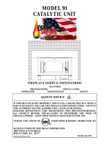
POSITIONING THE HEATER
NOTE: It is not necessary to direct connect this unit
unless installed in an improperly drawing fireplace or
oversized flue. It is recommended a chimney connector
be installed from the appliance flue collar to the first
fireplace chimney section.
When positioning the heater, the following conditions
MUST be met! (See Figure 2)
1. The front of the damper opening must be positioned
BEHIND the rear edge of the lintel to ensure proper
draft. (See Figure 2)
2. Center the heater in the fireplace opening.
MOUNTING THE TRIM PANELS
After the unit is positioned, mark the mounting position
of the trim panels as follows:
1. Set the side trim panels in place, flat against the
face of the fireplace. Mark down the front edge of
the trim panel with a pencil to make a vertical
reference line. (See Figure 3.)
2. Set the top (long) trim panel in place on top
of the unit. The panel should be flat against the
outside face of the fireplace, and standing vertically.
Mark along the lower edge of the trim panel with a
pencil to make a reference line for mounting.
3. Slide the unit out of the fireplace far enough to work
behind the trim panel reference lines.
FIGURE 3 MOUNTING TRIM PANELS
NOTE: Mount the top trim panel so that it sits in front of the top of the side trim panels..
9. Obtain the brass trim kit provided with insert kit and slip over the top and sides of trim panels. (Top ends of
brass may need to be trimmed to fit.)
10. Mount top trim panel by drilling mounting holes in center of trim panel mounting brackets, with top end side
of top panel overlapping side panel.
11. Using insulation provided, peel and stick to back of panels overlapping fireplace dimensions by 1" on each
side and top. (See Figure 4.)
12. Next using high heat silicone or furnace cement run heavy bead of caulking around where panels meet the
stove. (See Figure 4.)
13. Slide the unit back into the fireplace. Check to be sure that the trim panels (and brass) are properly positioned
and lie flat against the front of the fireplace. If panels are out of position, slide the unit out and reset by loos-
ening the mounting screws and repositioning in the slot. With bar lift stove up in front. Place insulation
across front and the surface of hearth or bottom of fireplace to make complete seal.
14. To check seal of panels, use candle flame and go around the entire area sealed by silicone and insulation. If
flame leans toward inside of fireplace, add additional insulation. This ensures an airtight seal.
FINAL CHECK
1. Recheck the specified clearances.
2. Remove all foreign material from the firebox area.
3. Open the primary air draft.
4. Plug the power cord into a 115V AC outlet if optional motor is being used.
5. Place rumpled pieces of newspaper in the stove. Light it and close the door. Ensure that the
stove draws properly through the primary draft.
6. Check for smoke leaks around the door.
7. Open the door and check for smoke escaping from the front of the stove. Smoking usually indicates
a defective or poorly positioned chimney. Some chimneys with a marginal draft can be pre-
heated by lighting newspaper and holding it near the open damper with a poker or fire tong. Once the
chimney heats up, a proper draft can usually be obtained.
FIGURE 4
CAUTION
THE UNIT IS PAINTED WITH A SPECIALLY FORMULATED
HIGH TEMPERATURE PAINT THAT CURES DURING THE FIRST TWO OR
THREE FIRINGS. YOU MAY NOTICE A SLIGHT SMOKING EFFECT AND AN
ODOR OF BURNING PAINT WHEN YOU BUILD THE FIRST FIRES. THIS IS
NORMAL AND IS NOT A CAUSE FOR ALARM. IN SOME CASES, THESE FUMES
WILL ACTIVATE A SMOKE ALARM. OPENING A WINDOW NEAR THE UNIT
WILL ALLOW THESE FUMES TO ESCAPE. DO NOT BUILD A LARGE, ROARING
FIRE UNTIL THIS CURING IS COMPLETE OR THE HEATER FINISH MAY BE
DAMAGED.
The connector and/or chimney should be inspected at least once a month during the heating
season to determine if a creosote buildup has occurred.
CAUTION
NEVER USE GASOLINE, GASOLINE-TYPE LANTERN FUEL, KEROSENE,
CHARCOAL LIGHTER FLUID OR SIMILAR LIQUIDS TO START OR "FRESHEN
UP" A FIRE IN THE HEATER. KEEP ALL SUCH LIQUIDS WELL AWAY FROM
THE STOVE WHEN IT IS IN USE. ALL FLUIDS OF THIS TYPE GIVE OFF
VOLATILE FUMES AND CAN AND WILL EXPLODE!! DON'T TAKE A CHANCE
WITH THE SAFETY OF YOUR HOME AND FAMILY.
SECTION III
PRE-FAB INSERT INSTALLATION
The Model 51 has been tested with the following:
Heatilator Security
Tempco Preway
Marco FMI
Woodside Majestic
The Model 51 will fit any of the models that are large enough to accept them.
NOTE: A full chimney liner is required in a Zero Clearance or pre-fab fireplace.
NOTE: The ash lip, smoke baffle, and smoke shelf may be removed if necessary to provide
room for these models. Any other alteration to the unit will void ALL NBC manufacturer's
responsibility and liability. The warning label below must be attached to the back of the fire -
place.
Except for the “NOTES” above, please follow the instructions for Masonry Insert Installation
including Minimum Clearances for stove and floor protector in Section II.
WARNING: This fireplace must be
restored to its original condition for safe use, if
the fireplace insert is removed.
SECTION IV
RESIDENTIAL FREESTANDING
INSTALLATION
PREPARING THE STOVE FOR INSTALLATION
1. Inspect the unit for any obvious physical damage.
2. Plug the power cord into a 115V AC outlet to test the motor and fan when optional motor is
being used.
3. Check the primary air draft control to ensure that it slides freely.
4. Remove any items from within the firebox. Spread the dropcloth on the floor behind the
heater. Next, tilt the heater so that the back is on the drop cloth.
5. If leg kit is to be used follow steps 1-5. Then obtain legs, bolts, washer & nuts. Attach the
legs to holes in bottom of unit.
6. If pedestal kit is being used, open the corresponding freestanding kit and obtain the stand.
Place the stand against the bottom of the heater (angle side to heater) at the marked line.
Center the stand left and right and mark screw locations on bottom through outer holes
of stand mounting angles. Set stand aside and drill four 7/32" holes in heater bottom.
(See Figure 4.)
Figure 4
8. Obtain four 1/4" self-tapping screws and secure the stand to the heater.
9. Reposition the heater to the upright position.
Chimney
Ceiling Exits:
This model is designed for connection to:
(1) Simpson Duravent (4) Metal Fab
(2) Security (5) Airjet
(3) Selkirk Metal Bestos (6) Jakes Evans
listed at 2100º pipe and parts. Follow pipe manufacturer's instructions carefully.
This room heater must be converted to (1) a chimney complying with the requirements for
Type HT chimneys in the Standard for chimneys, Factory-Built, Residential, Type and
Building Heating Appliance, UL 103, or (2) a code approved masonry chimney with a flue
liner.
CAUTION
SPECIAL METHODS ARE REQUIRED WHEN PASSING THROUGH A
WALL OR CEILING. SEE INSTRUCTIONS AND BUILDING CODES.
DETERMINING THE CHIMNEY LOCATION
A. CEILING EXIT (Using Single Wall Pipe and UL 103 HT type chimney system listed
with manufacturer in this section of manual.)
1. Suspend a plumb bob from the ceiling above the unit so that the weight is hanging in
the center of the flue exit. (A small weight on a string will serve as a plumb bob.)
Mark the ceiling where the string is suspended to locate the center of the chimney.
2. After locating the center of the hole, install the ceiling support box, chimney flashing
and rain cap per the chimney manufacturer’s instructions.
3. Now connect the stove and ceiling support box using #24 ga. minimum blued or
black steel connector pipe (DO NOT USE GALVANIZED PIPE). Connect each
section so the crimped end faces downward, and secure each section to each other
using at least three (3) sheet metal screws or rivets. Also use three (3) sheet metal
screws to fasten pipe to collar on heater. (See Figure 5.)
CEILING
ROOF
ATTIC
CEILING
"TEE" BOX ASSEM.
CENTER LINE
OF ELBOW
MARK PLUMB LINE
WALL
WALL PASS-THROUGH CONNE
C
18" MIN.
B. Wall Exit Into Metal Tee-Box
1. Mark the plumb line on the wall directly behind the center of the heater. (See Figure 6.)
NOTE: When using 24# ga. minimum blue or black steel pipe, maintain 18" between pipe
and ceiling.
2. Place the vertical portion of the heater pipe and the elbow in position and project a
point onto the plumb line level with the center of the elbow.
Figure 5
Figure 6
3. Measure up so there will be at least 1/4" rise per foot of horizontal connector pipe,
maintaining clearances to the ceiling as noted in Figure 6. This will give you the center of
the hole for the chimney penetration.
4. After locating the center of the penetration, install the tee-box and chimney as per the
chimney manufacturer's specifications.
5. Connect the chimney collar to the tee-box using #24 ga. minimum blued or black steel
connector pipe. DO NOT use galvanized pipe. Connect each section so the crimped end
faces downward, and secure each section to each other using three (3) sheet metal screws or
rivets.
C. Wall Exit Into Masonry (Using Single Wall Pipe)
1. Before connecting these units to a masonry chimney, determine that the masonry fireplace
wall pass-through connector thimble meets the NFPA-211 Code and local building codes
and is a minimum of 18" from the ceiling. If the connector thimble does not meet
these codes, the pass-through connector must be modified. (See Figure 7.)
Figure 7
Connectors may pass through walls or partitions constructed of combustible material if the
connector is:
(a) Either listed for wall pass-through or is routed through a device listed for wall pass-
through and is installed in accordance with the conditions of the listing.
(b) Selected or fabricated in accordance with the conditions and clearances as stated in
the NFPA-211 Code. Any unexposed metal that is used as part of a wall pass-through
system and is exposed to flue gases shall be constructed of stainless steel or other
equivalent material that will resist corrosion, softening, or cracking from flue gases at
temperatures up to 1800
o
F.
In addition, a connector to a masonry chimney shall extend through the wall to the inner
face or liner but not beyond, and shall be firmly cemented to masonry.
EXCEPTION: A thimble may be used to facilitate removal of the chimney connector for
cleaning, in which case the thimble shall be permanently cemented in place with high-
temperature cement.
2. Once the through-the-wall thimble codes are met, simply connect the chimney collar to
the wall pass-through connector using #24 ga. minimum, blued or black steel
connector pipe as follows:
(a) Maintain 1/4" rise per foot (horizontal length) from the appliance to the chimney.
(b) Connect each section so the crimped end faces downward.
(c) Secure each section to each other using at least three (3) sheet metal screws or rivets.
(d) Use three (3) sheet metal screws to fasten pipe to connector collar on heater.
D. Ceiling Exit-Close Clearance
1. Suspend a plumb bob from the ceiling above the unit so that the weight is hanging in the
center of the flue exit (A small weight on a string will serve as a plumb bob). Mark the
ceiling where the string is suspended to locate the center of the chimney hole.
2. After locating the center of the hole, install the ceiling support box, chimney flashing
and rain cap.
3. Next, install a New Buck Corporation chimney connector to the flue exit of the heater.
4. Install Double Wall Connector and chimney system per manufacturer’s written operating
instructions. See manufacturer's list of tested pipes in this manual.
Figure 8
Close Clearance Installation using: (1) 8" Simpson Dura-Vent double wall chimney
connector “Type DVL” and 8" Simpson Dura-Vent 2100º HT. “Type DP” chimney. (2) 8"
Security Type DL double wall connector and 8" Security Type "ASHT" High Temp Chimney.
(3)8" Selkirk Metal Bestos Model “DS” double wall connector- 8" Selkirk Metal Bestos
Model SSII Type HT Chimney System. (4) 8" Metal Fab Type “DW” double wall connector-
8" Metal Fab 2100 HT chimney. (5) 8" Air Jet. (6) Jakes Evans. For measurements refer to
page 23. For minimum clearances see pages 19 & 20.
Alcove Installation Clearances
Must use 6" Double Wall Connector and 6" Type HT Pipe listed for close clearance reduction
listed in this manual. For measurements refer to page 23. For minimum clearances see pages 19
& 20.
CEILING
ROOF
CHIMNEY CONNECTOR
FINAL CHECK
1. Recheck the specified clearances.
2. Remove all foreign material from the firebox area.
3. Open the primary air draft.
4. Plug the power cord into a 115V AC outlet when using with optional motor.
5. Place crumpled pieces of newspaper in the stove. Light it and close the door. Ensure
that the stove draws properly through the primary draft.
6. Check for smoke leaks around the door.
CAUTION
Open the door and check for smoke escaping from the front of the stove. Smoking usually
indicates a defective or poorly positioned chimney. Some chimneys with a marginal draft
can be preheated by lighting newspaper and holding it near the open damper with a poker
or fire tong. Once the chimney heats up, a proper draft can usually be obtained.
If a thorough review of the Troubleshooting Guide in the rear of the manual does not reveal
the problem, contact your dealer for assistance.
CAUTION
The unit is painted with a specially formulated high temperature paint that cures during
the first two or three firings. You may notice a slight smoking effect and an odor of
burning paint when you build the first fires. This is normal and is not a cause for
alarm. In some cases, these fumes will activate a smoke alarm. Opening a window near
the unit will allow these fumes to escape. DO NOT build a large, roaring fire until this
curing is complete or the heater finish may be damaged.
CLEARANCES FOR MODEL - 51
MINIMUM CLEARANCES TO COMBUSTIBLES
FREESTANDING
Figure 9
MODEL A B C D E F G
MODEL 51 16" 15" 18" 10" 4" 6" 20"
NOTE: All clearances are to combustibles without low clearance shields and using single wall
pipe and minimum floor protector. The clearances above may be reduced. Follow NFPA-211
codes if available or follow instructions on next page.
BACK WALL
SIDE WALL
A
E
B
F
C
C
D
G
C
D
D
G
  • Page 1 1
  • Page 2 2
  • Page 3 3
  • Page 4 4
  • Page 5 5
  • Page 6 6
  • Page 7 7
  • Page 8 8
  • Page 9 9
  • Page 10 10
  • Page 11 11
  • Page 12 12
  • Page 13 13
  • Page 14 14
  • Page 15 15
  • Page 16 16
  • Page 17 17
  • Page 18 18
  • Page 19 19
  • Page 20 20
  • Page 21 21
  • Page 22 22
  • Page 23 23
  • Page 24 24
  • Page 25 25
  • Page 26 26
  • Page 27 27
  • Page 28 28
  • Page 29 29
  • Page 30 30
  • Page 31 31
  • Page 32 32
  • Page 33 33
  • Page 34 34
  • Page 35 35
  • Page 36 36

BuckMaster 51 User manual

Category
Fireplaces
Type
User manual
This manual is also suitable for

BuckMaster 51 is a non-catalytic wood heater designed to provide efficient and clean heating for residential and mobile home installations. It features a large firebox for long burn times, secondary air tubes for improved combustion, and an optional room air blower for better heat distribution. The BuckMaster 51 can be installed in masonry fireplaces, pre-fab fireplaces, and as a freestanding unit, offering versatility in placement. It is also equipped with safety features like a floor protector and close clearances shields, ensuring safe operation.

Ask a question and I''ll find the answer in the document

Finding information in a document is now easier with AI