Page is loading ...

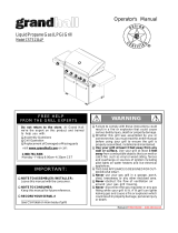
Owner’s Manual
Customer Service Helpline: If you have questions about assembly or grill operation, or if there are damaged or
missing parts when you unpack this unit from the shipping box, call us Monday through Friday at 1-800-752-3085
n
W
ARNING:
All barbecues and carts are designed for outdoor use only!
All barbecues are not intended for commercial use.
n
W
ARNING:
Read this Owner’s Manual carefully and
be sure your gas grill is properly
assembled, installed and maintained.
Failure to follow these instructions
could result in serious bodily injury
and/or property damage. This gas grill
is intended for outdoor use only and is
not intended to be installed in or on
recreational vehicles or boats.
Note to Installer: Leave this Owner’s
Manual with the consumer after delivery
and/or installation.
Note to Consumer: Leave this
Owner’s Manual in a convenient place
for future reference.
P80151009A
RV 041205
America's
Barbecue
Grill
Superstores
Design Certified
Unit approved by
CSA Laboratories under standard
ANSI Z21-58b-2002/CGA 1.6b-2002
52” All Grill BBQ
YN662AGLP
YN662AGNG
YN662CT
(Cart Only)
38”
All Grill BBQ
YN663LP
YN663NG
YN663CT
(Cart Only)
52” BBQ with Side Burner
YN662LP
YN662NG
YN662CT (Cart Only)


READ THESE SAFETY INSTRUCTIONS
n
WARNING
Fuels used in gas or oil-fired appliances and the products of
combustion of such fuels, contain chemicals known to the
State of California to cause cancer, birth defects and/ or
other reproductive harm.
This warning is issued pursuant to California Health &
Safety Code Sec. 25249.6.
n
WARNING
Failure to comply with these instructions could result in a
fire or explosion that could cause serious bodily injury,
death, or property damage.
n
WARNING
Your grill will get very hot. Never lean over the cooking
area while using your grill. Do not touch cooking surfaces,
grill housing, grill lid or any other grill parts while the grill is
in operation, or until the grill has cooled down after use.
Failure to comply with these instructions may result in
serious bodily injury.
Grill lnst
allation Codes
This gas grill must be installed in accordance with all
local codes. In areas without local codes, follow the latest
edition of the National Fuel Gas Code ANSI Z223.1. In
Canada, installation must conform to standard CAN/CGA
1b149.1 or 1-b149. 2 (Installation Code for Gas Burning
Appliances and Equipment) and all local codes.
Proper Placement and Clearance of Grill
Never use your gas grill in a garage, porch, shed,
breeze way or any other enclosed area. Your gas grill is to
be used outdoors only, at least 24 inches from the back
and 18 inches to the side of any combustible surface.
Your gas grill should not be placed under any surface that
will burn. Do not obstruct the flow of ventilation air around
the gas grill housing.
This outdoor gas grill is not intended to be installed
in or on recreational vehicles and/or boats.
PROPANE MODELS:
Correct LP Gas Tank Use
LP gas grill models are designed for use with a standard
20 lb. Liquid Propane Gas (LP gas) tank, not included with
grill box. Never connect your gas grill to an LP gas tank that
exceeds this capacity. A tank of approximately 12 inches in
diameter by 18-1/2 inches high is the maximum size LP gas
tank to use. A Propane tank with an OPD (Overfill Prevention
Device) must be used. This safety feature prevents the tank
from being over-filled which can cause malfunction of the LP
gas tank, regulator and/or grill.
The LP gas tank must be constructed and marked in
accordance with specifications of the U.S. Dpt. of
Transportation (DOT). In Canada, the LP gas tank must
meet the Canadian Transportation and Communications
(CTC) specifications. Also be sure to read and follow all LP
instructions on the following page.
If the outdoor cooking gas appliance is not in use, the
gas must be turned off at the supply cylinder.
(a) Do not store a spare LP-gas cylinder under or near
this appliance;
(b) Never fill the cylinder beyond 80 percent full; and
(c) If the information in (a) and (b) is not followed
exactly, a fire causing death or serious injury may
occur.
1. The LP gas tank has a shutoff valve, terminating in an
LP gas supply tank valve outlet, that is compatible with
a Type 1 tank connection device. The LP gas tank must
also have a safety relief device that has a direct com-
munication with the vapor space of the tank.
2. The tank supply system must be arranged for vapor
withdrawal.
3. The LP gas tank used must have a collar to protect the
tank valve.
! Never connect an unregulated LP gas tank to your gas
grill. The gas regulator assembly supplied with your gas
grill is adjusted to have an outlet pressure of 11" water
column (W.C.) for connection to an LP gas tank.
! Only use the regulator and hose assembly supplied with
your gas grill. Replacement regulators and hose assem-
blies must be those specified by manufacture.
! Have your LP gas tank filled by a reputable propane gas
dealer and visually inspected and re-qualified at each
filling.
! Never fill the gas tank beyond 80% full. Have your
propane gas dealer check the release valve after every
filling to ensure that it remains free of defects.
! Always keep LP gas tanks in an upright position.
! Do not store (or use) gasoline or other flammable
vapors and liquids in the vicinity of this gas grill.
! An LP gas tank that is not connected for use must NOT
be stored on bottom shelf or in the vicinity of this or any
other gas grill.
! Do not subject the LP gas tank to excessive heat.
! Never store an LP gas tank indoors. If you store your
CSA label
located at
rear of unit
- 2 -

gas grill in the garage or other indoor location, always
disconnect the LP gas tank first and store it safely out-
side and out of reach of children.
! LP gas tanks must be stored outdoors in a well-ventilat-
ed area. Disconnected LP gas tanks must not be stored
in a building, garage or any other enclosed area.
! When your gas grill is not in use the gas must be turned
off at the LP gas tank.
! The regulator and hose assembly must be inspected
before each use of the grill. If there is excessive abra-
sion or wear or if the hose is cut, it must be replaced
prior to the grill being used again.
! Keep the gas regulator hose away from hot grill surfaces
and dripping grease. Avoid unnecessary twisting of
hose. Visually inspect hose prior to each use for cuts,
cracks, excessive wear or other damage. If the hose
appears damaged do not use the gas grill. Call our serv-
ice center at 1-800-752-3085.
! Never light your gas grill with the lid closed or before
checking to insure the burner tubes are fully seated over
the gas valve orifices.
! Never allow children to operate your grill. Do not allow
children to play near your grill.
n
WARNING
A strong gas smell, or the hissing sound of gas indicates a
serious problem with your gas grill or the LP gas tank.
Failure to immediately follow the steps listed below could
result in a fire or explosion that could cause serious bodily
injury, death, or property damage.
! Shut off gas supply to the grill.
! Turn the Control Knobs to the OFF position.
! Open grill lid.
! Get away from the LP gas tank.
! Do not try to fix the problem yourself..
! If odor continues or you have a fire you cannot extin-
guish, call your fire department.
Do not call near the LP gas tank because your telephone is
an electrical device and could create a spark resulting in
fire and/or explosion.
NOTE: The normal flow of gas through the regulator and
hose assembly can create a humming noise. A low volume
of noise is perfectly normal and will not interfere with opera-
tion of the grill. If humming noise is loud and excessive you
may need to purge air from the gas line or reset the regula-
tor excess gas flow device. This purging procedure should
be done every time a new LP gas tank is connected to your
grill. For help call the Customer Service Helpline for assis-
tance.
Built-in Units Utilizing Natural Gas
When connecting a built-in unit to the natural gas sup-
ply in your home, please ensure the pipe joint compound is
resistant to the action of natural gas. In addition, please
observe the following:
The barbecue and its individual shut-off valve must be
disconnected from the gas supply piping system during any
pressure testing of that system at test pressures in excess
of ½ psi (3.5 kPa).
The barbecue must be isolated from the gas supply
piping system by closing its individual
manual shut-off valve
during any pressure testing of the gas supply piping system
at test pressures equal to or less than ½ psi (3.5 kPa)
The units are supplied from the factory equipped for
use with natural gas and includes a natural gas regulator.
If operation with propane gas is desired, you must pur-
chase a Propane Model. In addition, a Propane Gas
Regulator MUST
be installed in the gas supply line from
the propane gas tank.
Please remember to check all gas connections for
leaks after the piping is completed. Follow the procedure
under the heading "CAUTION: LEAK CHECKING."
n CAUTION: BEWARE OF FLASHBACK
CAUTION: Spiders and small insects occasionally spin
webs or make nests in the
grill burner tubes during
transit and warehousing.
These webs can lead to a
gas flow obstruction which
could result in a fire in and
around the burner tubes.
This type of fire is known as a ”FLASHBACK” and can
cause serious damage to your grill and create an unsafe
operating condition for the user.
Although an obstructed burner tube is not the only cause of
”FLASHBACK”, it is the most common cause.
To reduce the chance of ”FLASHBACK”, you must clean the
burner tubes before assembling your grill, and at least once
a month in late summer or early fall when spiders are most
active. Also perform this burner tube cleaning procedure if
your grill has not been used for an extended period of time.
BEFORE USING YOUR GRILL
To reduce the chance of ”FLASHBACK” clean the burn-
er tubes and burners before fully assembling your grill.
Unscrew the bolt at the rear of the burner using a screw-
driver. Carefully lift each burner up and away from the gas
valve orifice, then refer to Fig1 and perform one of these
three cleaning methods:
1. Bend a stiff wire, (a lightweight coat hanger works well)
into a small hook as shown below. Run the hook through
the burner tube and inside the burner several times to
remove any debris.
- 3 -

2. Use a bottle brush with a flexible handle. Run the brush through
the burner tube and inside the burner several times, removing any
debris.
3. Preferably, an air hose should be used to force air through each
burner tube. The forced air should pass debris or obstructions
through the burner and out the ports.
Figure 1
GAS VALVE
ASSEMBLY
BURNER TUBE
ORIFICE
Figure 2
SPARK
ELECTRODE
ASSEMBLY
BURNER TUBE
PHILLIPS HEAD
SCREW
BURNER PORTS
BURNER
GAS
COLLECTOR
BOX
n
WARNING
The location of the burner tube with
respect to the orifice is vital for safe
operation. Check to ensure the orifice
is inside of the burner tube before
using your gas grill (Figure 1).
If the burner tube does not fit over the
valve orifice, lighting the burner may
cause explosion and/or fire.
- 4 -
Outdoor BBQ Built-in Installation Specifications
Prior to installing unit, side and rear trims must be installed to fully support the unit.
Built-in T
rim Kit Installation:
Carefully remove the stainless steel trim pieces from the carton and attach Left, Right & Rear stainless trims to left, right &
rear sides of barbecue using 10 bolts & 2 nuts. Check to make sure they are aligned flush with the side barbecue face
and top before fully tightening the bolts.
NOTE:
When choosing a location for your Gas grill, keep in mind that it should not be located under any overhead com-
bustible construction. The side and bottom of the grill should not be any closer than 18 inches to combustible construction,
and the back of the grill should not be any closer than 24 inches to combustible construction.
TO CLEAN BURNER TUBE
INSERT HOOK HERE
Figure 3a
Rear Trim:
52" BBQ uses 4 bolts
38" BBQ uses 3 bolts and Wok uses 2 bolts
YN662AGLP , YN662AGNG
Rear Trim:
(A) - (6X) 3/16” x 3/8” Phillips Head Screws
Left & Right Trim:
(B) -(6X) 3/16” x 3/8” Pan Head with Cross Recess Screw
(C) -(10X) 1/4” x 1/2” Phillips Head Screw
Figure 3b
6X (A)
10X (C)
6X (B)

NOTE: When using Propane, EXTREME CAUTION should be
used to provide ample ventilation of vapor from the enclosure.
LP Gas vapor is heavier than air and SERIOUS INJURY from
a DANGEROUS EXPLOSION could occur if LP Gas is allowed
to accumulate in an enclosure and then ignited. Both the
Barbecue enclosure and LP cylinder enclosure require venting
that must be provided at the floor level of the enclosure to allow
any leaking LP Gas vapor to escape. Upper & lower ground-
level vents (20 sq. in. minimum each) MUST BE PROVIDED
on both sides of built-in construction. Please ask a Barbeques
Galore associate for full details.
NOTE:
When installing a barbecue equipped for liquid propane
in an island, the propane tank must be in a separate enclosure
that is completely isolated from the barbecue. It must be cross-
ventilated in accordance with the current standard. The
propane tank MUST NEVER be installed directly under the bar-
becue.
NOTE:
Upper & lower ground-level vents (20 sq. in. minimum
each) MUST BE PROVIDED for combustion air on both sides
of built-in construction. Please ask a Barbeques Galore asso-
ciate for full details.
Barbecues must be installed in accordance with CSA
specifications and all local building codes.
Air Vents
Louvers on BBQ must
remain unobstructed to
allow for combustion air.
Figure 6
Natural Gas
Installation
Access must
be provided to
Shut-off Valve
- 5 -
Depth
Width
Height
Side*
Rear*
6” minimum clear-
ance from cutout
(for hood)
Model Height Width Depth Side* Rear*
52" YN662 10" 52-3/4" 24-1/2" 18" 24"
38" YN663 10" 38-3/4" 24-1/2" 18" 24"
Side Burner 10" 17-1/2" 24-1/2" 18" 24"
non-combustible
construction
Built-in Model Cutout Dimensions &
Clearance to Combustibles
* Rear & Side Clearances indicated are to combustible
construction
Figure 4
nWARNING
Vapors from products containing Chlorine and other caustic
chemicals can cause Stainless Steel flexible connectors to
corrode. THESE PRODUCTS SHOULD NOT BE STORED IN
AN ISLAND OR NEAR THE connector. Cleaning solutions,
Household Chemicals and Solder fluxes can also cause pin-
holes if they come in contact with these connectors and
MUST be washed off immediately with water.
Stainless
Flexline
Non-combustible
Construction
Vented on
BOTH SIDES
of Island
Vented Access Door
CSA Approved Propane Regulator
CSA Approved
Rubber Gas Hose
QCC-1/OPD
Tank
Figure 5
Clamp down
flexline

- 6 -
Cart & Barbecue Assembly (requires an assistant)
1. Unpack Cart.
2. Unpack Barbecue.
3. Position barbecue on top of Cart.
4. Remove Left & Right Side Panels on both sides of cart
as shown in Figure 9.
5. With the help of your assistant, position barbecue on
top of Cart and align mounting holes as shown in Figure
10.
6. Secure with two Mushroom Head bolts and nuts at both
front sides. Do not tighten until all fasteners are in
place.
7. Secure with Washer Head bolts (no nuts required) as follows:
YN662 (52” BBQ’s) 6 bolts at rear & side
YN663 (38” BBQ) 5 bolts at rear & side
You may need your assistant to adjust the position of the
barbecue so that the holes are all aligned.
8. Once barbecue & cart are aligned, tighten all bolts.
9. Replace Left & Right Side Panels.
Figure 9
Figure 7
NATURAL GAS MODELS ONLY
Side Panel
Bolts
CSA Approved
Rubber Gas Hose
Cart model LP Gas
Connection
3/8 FF x 3/8 MF
on Propane models
Figure 10
Nutserts
Washer
Head
Bolts
Nuts at
front only
(2)
Bolts
Figure 8
IN
OUT
CSA Approved
Natural Gas
Regulator
Yellow Teflon Pipe Thread Sealant
is recommended for use on all
pipe thread connections EXCEPT
flared threads.
Stainless
Flexline
Natural
Gas
Supply
Close Nipple
Shut-off Valve
1/2-1/2” NPT
IMPORTANT: Regulator must be on the Barbecue or your
warranty is void.
Extension Fitting for manifold
Extension Fitting for outlet (NG only)

Grand Turbo YN662CT, YN663CT Models
Cart & Cart Trim Plate Assembly Instructions
- 7 -
P81201013A
1. Open the left door from cabinet cart. Unscrew the left cart side panel trim plate from the left cart side
panel.
2. Repeat for right cart side panel trim plate.
3. Pull out the upper drawer, Push up black tenon on the left slide and push down black tenon on the right
slide to remove the upper drawer.
4. Repeat for lower drawer.
Cart & Cart Trim Plate Assembly (requires an assistant)
1
2
1. Place the cart trim plate under the cart.
2. Be sure the rear of cart trim plate are inserted into the cart trim plate bracket.
3/16"x1/2” Phillips Head Screw
Qty. 12
(from left & right cart side panel
trim plate)

3
1/4”x1/2”Phillips Head Screw
Qty. 4
4
- 8 -
1. Install the left cart side panel trim plate to the left cart side panel.
2. Repeat for right cart side panel trim plate.
3. Install the upper drawer, Push up black tenon on the left slide and push down black tenon on the right
slide to install the upper drawer to cart.
4. Repeat for lower drawer.
3/16"x1/2” Phillips Head Screw
Qty. 12
(from left & right cart side panel
trim plate)
Align the holes on the cart bottom shelf
and the caster seats
with the threaded holes on the cart trim plate.
Tighten securely using 4 screws and 3 bolt provided.
1/4"x2-1/2" Pan Head with Cross
Recess Bolt
Qty. 3 (for YN662CT Model)
Qty. 2 (for YN663CT Model)

Y
N
6
6
2
C
T
M
o
d
e
l
YN663CT Model
- 9 -

- 10 -
YN662AGLP , YN662AGNG
Parts Diagram
Figure 11

YN662LP , YN662NG
Parts Diagram
Figure 12
- 11 -

YN663LP , YN663NG
Parts Diagram
Figure 13
- 12 -

-13 -
1
2
3
4
5
6
7
8
9
10
11
12
13
14
15
16
17
18
19
20
21
22
23
24A
24B
25
26
27
28
29
30
31
32
33
34
35
36
37
38
39
40A
40B
P/NQTYDESCRIPTION
ITEM
Lid Assembly
Lid Handle Bracket
Lid Handle
Lid Handle Heat-Insulating Spacer
Name Plate
Temperature Gauge
Protective Pad
Bowl Side Panel, Left
Bowl Side Panel, Right
Lid Hing w. Nut
Bowl Side Panel/Trim Plate/Left
Bowl Side Panel/Trim Plate/Right
Burner Bracket
Burner/Main
Burner Air Shutter
Gas Collector Box with Electrode
Electric Wire Set
Control Knob for Main/Smoker
Burners
Control Knob Seat
Grease Tray Heat Shield,Upper
Smoker Drawer Bracket
Smoker Drawer
Smoker Drawer Filler
Grease Tray Assembly
Grease Tray Heat Shield,Lower
Lighting Tube
Gas Valve/Manifold Assembly
LPG
NG
Extension Fitting for Manifold
LPG
NG
Extension Fitting - Outlet (NG only)
Electric Ignitor, 4-Ports
Cooking Rack/Secondary
Cooking Grid - Large
Cooking Grid - Small
Flame Tamer/Rack
Flame Tamer/Ceramic
Door Hinge Bracket -Left Top
Door Hinge Bracket -Right Top
Door Hinge Bracket-Left Bottom
Door Hinge Bracket -Right Bottom
Door Stop/2 pcs
Caster, 2.5 in.,without Brake/Front
Caster, 2.5 in.,with Brake/Rear
41
42
43
44
45
46
47
48
49
50
51
52
53
54
55
56
A1
A2
A3
A4
A5
A6
A7
A8
A9
A10
A11
B1
B2
B3
---
Tank Pull-Out Tray Assembly (Option)
Cart Bottom Shelf /Trim Plate
Door
Door Trim Plate,Left
Door Trim Plate, Right
Door/Drawer Handle
Towel Rack
Towel Rack Bracket
Spice Basket
Side Shelf Bracket, Left / Right
Side Shelf
Side Shelf Lock
Drawer Panel
Regulator with Hose/LPG
Regulator/NG
Extension Fitting - Inlet (NG only)
Back Burner Frame
Back Burner Assembly
LPG
NG
Back Burner Wind Shield
Extension Tube for Back Burner
Thermocouple/Back Burner
Back Burner Electrode
Thermocouple Bracket, Left
Thermocouple Bracket, Right
Thermocouple Protector
Control Knob for Back Burner
Control Knob Seat
Trim Panel, Left
Trim Panel, Right
Trim Panel, Rear
Owner’s Manual
Y0130012
P00303016E
P00205064B
P06801002A
P00407003D
P00607101C
P05518002I
P0072016EC
P0072116EC
P05511006A
P07514004A
P07514005A
P02216024A
P02001002E
P05524008A
P02610018A
P02615056A
P03411083L
P03415034A
P06904008C
P06708001A
P06701002A
P06704004A
Y0270007
P06904013C
P05507003A
Y0060194
Y0060195
P03901011A
P03901015A
P03901013A
P02502024C
P01518002B
P01606002B
P01606006B
P01720005B
P01804002A
P03314035C
P03314036C
P03314037C
P03314038C
P05517016E
P05117007E
P05110001E
Y0340022
P07516001A
P04301001A
P07506001A
P07507001A
P00215002L
P05209003A
P05212008A
P05203001A
P01208001A
P01105030B
P05501003A
P01901004B
P03601011A
P03628001B
P03901017A
P02011025E
Y0030017
Y0030018
P06906017C
P03701011A
P05305005A
P02614008C
P03328012C
P03328013C
P06909002C
P03411093L
P03415034A
P07505007A
P07504007A
P07515015A
P80151009A
DESCRIPTION
1
1
2
1
1
4
1
1
1
2
2
4
2
1
1
1
1
1
1
1
2
2
2
1
1
2
2
2
1
1
1
1
P/N
QTY
1
2
1
2
1
1
4
1
1
2
1
1
1
8
8
4
1
8
8
1
1
1
1
1
1
1
1
1
1
1
2
1
4
1
2
16
1
1
1
1
2
2
2
ITEM
Parts List for model YN662AG(LP/NG) only

1
2
3
4
5
6
7
8
9
10
11
12
13
14
15
16
17
18
19
20
21
22
23
24
25
26
27
28
29
30
31
32A
32B
33
34
35
36
37
38A
38B
38C
38D
39
40
- 14 -
Lid Assebbly
Temperature Gauge
Name Plate
Lid Handle Bracket
Lid Handle
Handle Heat-Insulating Spacer
Protective Pad, Lid Front
Protective Pad, Lid Rear
Cooking Rack/Secondary
Cooking Grid/Large
Cooking Grid/Small
Flame Tamer/Ceramic
Flame Tamer/Rack
Lid Hinge with Nut
Bowl Side Panel/Trim Plate/Left
Bowl Side Panel/Trim Plate/Right
Smoker Drawer Bracket
Grease Draining Tray Heat Shield,Upper
Burner/Main
Burner Air Shutter
Gas Collector Box with Electrode
Extension Tube for Manifold
Extension Tube Fitting
Extension Fitting (LPG only)
Extension Fitting (NG only)
Gas Valve/Manifold Assembly (LPG only)
Gas Valve/Manifold Assembly (NG only)
Control Knob for Main/Side/Smoker Burners
Control Knob for Back Burner
Control Knob Seat
Electric Ignitor, 4-Ports
Smoker Drawer
Smoker Drawer Filler
Grease Tray Assembly
Grease Draining Tray Heat Shield,Lower
Back Burner Assembly (LPG olny)
Back Burner Assembly (NG olny)
Back Burner Wind Shied
Back Burner Extension Tube
Lighting Tube
Regulator with Hose/LPG
Extension Fitting - Inlet (NG only)
Regulator/NG
Extension Fitting - Outlet (NG only)
Extension Fitting (NG only)
Cart Bottom Shelf/Trim Plate
Drawer Panel
Y0130010
P00607101C
P00407003D
P00303016E
P00205025B
P06801002A
P05518002I
P05518005I
P01516001B
P01606001B
P01606002B
P01804002A
P01720026B
P05511006A
P07514015A
P07514016A
P06708001A
P06904001C
P02001002E
P05524008A
P02610018A
P03715001A
P03907003A
P03901011A
P03901012A
Y0060137
Y0060138
P03411083L
P03411093L
P03415034A
P02502024C
P06701002A
P06704001A
Y0270005
P06904014C
Y0030015
Y0030016
P06906002C
P03701008A
P05507001A
P03601011A
P03901017A
P03628001B
P03901016A
P03901015A
P07516001A
P01901004B
P/N
YN662
QTY
YN662
P/N
YN663
QTY
YN663
DESCRIPTION
ITEM
Y0130010
P00607101C
P00407003D
P00303016E
P00205025B
P06801002A
P05518002I
P05518005I
P01516001B
P01606001B
P01606002B
P01804002A
P01720026B
P05511006A
P07514015A
P07514016A
P06708001A
P06904001C
P02001002E
P05524008A
P02610018A
P03715001A
P03907003A
P03901011A
P03901012A
Y0060139
Y0060140
P03411083L
P03411093L
P03415034A
P02502024C
P06701002A
P06704001A
Y0270006
P06904014C
Y0030015
Y0030016
P06906002C
P03701008A
P05507001A
P03601011A
P03901017A
P03628001B
P03901016A
P03901015A
P07516002A
P01901006B
1
1
1
2
1
2
2
2
1
2
1
12
1
2
1
1
1
1
6
6
3
1
1
1
1
1
1
8
1
9
2
1
1
1
1
1
1
1
1
1
1
1
1
1
1
1
2
1
1
1
2
1
2
2
2
1
2
1
12
1
2
1
1
1
1
6
6
3
1
1
1
1
1
1
6
1
7
1
1
1
1
1
1
1
1
1
1
1
1
1
1
1
1
2
Parts List

P/N
YN662
QTY
YN662
P/N
YN663
QTY
YN663DESCRIPTION
ITEM
41
42
43
44
45A
45B
46
47
48
49
50
51
52
53
54
55
56
57
A1
A2
A3
B1
B2
B3
B4
B5
B6
---
Door Hinge Bracket, Left Top
Door Hinge Bracket, Right Top
Door Hinge Bracket, Left Bottom
Door Hinge Bracket, Right Bottom
Caster, 2.5 in., without Brake/Front
Caster, 2.5 in., with Brake/Rear
Tank Pull-Out Tray Assembly (Option)
Door
Door Trim Plate,Left
Door Trim Plate,Right
Door/Drawer Handle
Towel Rack
Towel Rack Bracket
Spice Basket
Side Shelf
Side Shelf Bracket, Left
Side Shelf Bracket, Right
Side Shelf Lock
Trim Panel, Left
Trim Panel, Right
Trim Panel, Rear
Side Burner Lid
Side Burner Body
Side Burner Pot Support
Side Burner with Brass Ring
Side Burner Electrode/Front
Side Burner Electrode/Rear
Owner’s Manual
P03314035C
P03314036C
P03314037C
P03314038C
P05117007E
P05110001E
Y0340022
P04301001A
P07506001A
P07507001A
P00215002L
P05209003A
P05212008A
P05203001A
P01105030B
P01209002A
P01210002A
P05501003A
P07505002A
P07504002A
P07515008A
P00115376A
P02301003B
P00806011B
P02001014A
P02607034C
P02607035C
P80151009A
P03314035C
P03314037C
P05117007E
P05110001E
Y0340022
P04301001A
P07506008A
P00215002L
P05209003A
P05212008A
P05203001A
P01105030B
P01209002A
P01210002A
P05501003A
P07505002A
P07504002A
P07515009A
P80151009A
1
1
1
1
2
2
1
2
1
1
4
1
1
1
2
1
1
4
1
1
1
1
1
1
1
1
1
1
1
1
2
2
1
1
1
3
1
1
1
2
1
1
4
1
1
1
1
Parts List
- 15 -

Assembly Instructions
1. Unscrew Igniter Cap(s) located on the grill Control
Panel and remove the Contact(s) and Spring(s) from
the Battery Holder(s).
2. Place an “AA” battery into Battery Holder(s). Be sure
to place the positive pole facing toward you. See
Figure 14.
3. Place the Spring over the AA battery, then place the
Contact on top of the Spring. Screw Igniter Cap(s)
back onto the grill Control Panel.
Electrode Check - Requires an Assistant
Before placing the cooking components into your grill,
ensure that the Spark Electrode Tips are properly positioned
within each Gas Collector Box (a 3-1/4” wide stainless mech-
anism found at the front between each set of burners.) The
easiest way to ensure this is to perform this Electrode Check:
1. Be sure all Control Knobs are set to ”OFF”. Open the Grill
Lid.
2. Have an assistant stand behind to the right of the grill and
look down at the Gas Collector Box of the main burners.
NEVER put your face inside Grill Head.
3. Press center Igniter Cap and have assistant watch for a
small blue spark within each Gas Collector Box. if a spark
is present the Electrode Tips are properly positioned.
4. If no spark is seen, the Spark Gap shown in Figure 15
needs to be adjusted as follows:
! Using an adjustable wrench, loosen the Inside Nut just
until the Gas Collector Box can be maneuvered and
turned upward.
! The gap between the Spark Electrode Tip and Spark
receiver should be approximately 3/16”.
! if the gap is wider than 3/16” use a pair of long nose pli-
ers and gently squeeze the Gas Collector Box until the
gap is correct.
! Return the Gas Collector Box to its original horizontal
position, secure the Inside Nut and try the Electrode
Check again.
lnstalling Cooking Components
Important: Before cooking on your grill for the first time,
wash the cooking grids and warming rack with warm, soapy
water. Rinse and dry thoroughly. Season with cooking oil
regularly. After cooking is completed, turn grill to HIGH set-
ting for about five minutes to burn off excess grease or food
residue.
1. Place the Ceramic Flame Tamers on the Ceramic Rack
and place on the lower ledge above the burners.
2. Evenly space the Stainless Steel Cooking Grids on the
ledge above the Flame Tamers.
3. Place the Upper Warming Rack into the holes on the
upper left and upper right of the back burner frame with
the bottom resting in the slots on either side of the grill
bowl.
BATTERY HOLDER
AA BATTERY
CONTACT SPRING
CONTACT
IGNITER
CAP
Figure 14
Figure 15
INSIDE NUT
GAS COLLECTOR BOX
SPARK ELECTRODE TIP
3/16”
SPARK
GAP
UPPER
WARMING RACK
COOKING
GRID
CERAMIC
FLAME TAMER
POT
SUPPORT
Figure 16
- 16 -
CERAMIC
RACK

Connecting A Liquid Propane (LP) Gas Tank To Your Grill
1. You will need to install the special fitting 3/8"FF (Female
Flare) x 3/8"MF (Male Flare) onto the outlet manifold so
that it is easier to attach the Hose and Regulator (see
Pg.6, Fig.8). Attach LP Hose & Regulator assembly to
the fitting and ensure that both connections are gas tight
(Do NOT use Pipe Sealant on these flare connections).
2. Open the left door. Pull out the LPG tank drawer (these
are not supplied with Natural Gas models). Note:-Tank
drawer must be installed into the cart by the con-
sumer as per the instructions supplied with drawer
kit. Place the 20 Ib cylinder with foot ring into the hole in
the drawer. See Figure 17. Make sure the tank valve is
in the OFF position. Make sure the gas tank is in the
upright position. Use the 5/16” x 90mm wing bolt provid-
ed to secure gas tank.
3. Check the tank valve to ensure it has proper external
mating threads to fit the hose & regulator assembly pro-
vided. See Figure 18. (Type 1 connection per ANSI
Z21.58a-1998)
4. Make sure all burner valves are in the OFF position.
5. Inspect the valve connection port and regulator assembly.
Look for damage or debris. Remove any debris. Inspect
hose for damage. Never use damaged or plugged equip-
ment.
6. When connecting the hose and regulator assembly to the
tank valve, hand tighten nut clockwise to a full stop. Do
not use a wrench to tighten because it could damage the
Quick Coupling Nut and result in a hazardous condition.
7. Open the tank valve fully (counterclockwise). Use a
soapy water solution to check all connections for leaks
before attempting to light your grill. See ”Checking for
Gas Leaks” on page 16. If a leak is found, turn the tank
valve off and do not use your grill until the leak is
repaired.
Disconnecting An LP Gas Tank From Your Grill.
1. Turn the burner valves and LP gas tank valve to the full
OFF position. (Turn clockwise to close.)
2. Detach the hose and regulator assembly from the LP
gas tank valve by turning the Quick Coupling Nut coun-
terclockwise.
CAUTION: When the appliance is not in use, the gas
must be turned off at the supply tank.
Connecting Natural Gas
To Your Grill
1. You will need to install the Special fitting 3/4” FF x 3/4”
MP. Connect from the outlet manifold to the 12ft. Hose
and QD(Quick Disconnect) on cart model or the Natural
Gas Regulator to stainless steel flexline & shut-off valve
for built-in installation.
2a. Built-in Model: Install the Shutoff Valve, Close Nipple,
Stainless Steel Flexline to the Natural Gas Regulator.
The Shutoff Valve must be intalled directly to the outlet
pipe and the Natural Gas Regulator must be connect
directly to the outlet manifold.
2b. Cart model: Pass the hose through the hole in the cart
and connect the 12ft hose directly to the Natural Gas
Regulator. Make sure you have installed a Shutoff
Valve on the supply line.
3. Turn the gas supply on and fully open the shutoff valve.
Use a soapy water solution to check all connections for
leaks before attempting to light your grill. See ”Checking
for Gas Leaks” on page 16. If a leak is found, turn the
gas supply off and do not use your grill until the leak is
repaired.
Figure 17
GAS
TANK
TANK
DRAWER
WING BOLT
Models YN662
and YN663
Figure 18
GAS
TANK
TANK
DRAWER
QUICK CONNECT
COUPLING NUT
- 17 -
Type 1 connection per
ANSI Z21.58a-1998

Operating Fuel Gauge
Calibration Procedure:
1. Before installing batteries be sure the gas tank is not
mounted in the Tank Tray.
2. Pull out the Tank Tray. Rotate the Battery Box Retainer
on the bottom of Tank Tray. See Figure 19.
3. Carefully remove the Battery Connector with electric
wire from the bottom of Tank Tray. Insert 9V battery (pro-
vided) to the battery Connector. Return the assembled
Battery to position.
4. Rotate the Battery Box Retainer back into place.
5. During calibration the Fuel Gauge Display shows the
tank images of FULL and then EMPTY quickly.
Fuel Gauge Display - Operating
Press the “CHECK” button to operate Fuel Gauge Display
with the gas tank mounted in the Tank Tray.
NOTE: Tank must be positioned in tray for Fuel Gauge
Display check.
1. Fuel Display: Indicates gas tank fill level.
2. Fuel Warning Display: When the gas tank fill level is on
the last row, a warning signal will sound for approximate-
ly 3 seconds to warn you that the tank volume is near
empty.
3. Battery Warning Display: A low battery warning light will
illuminate when the battery voltage drops to a low level.
Replace the batteries.
NOTES:
1. The Fuel Gauge Display lasts for approximately 20 sec-
onds each time you press the “CHECK” button. After 20
seconds, the Fuel Gauge Display turns off automatically.
If you press the button a second time within 20 seconds,
the Fuel Gauge Display will be turned off manually. If
you press the button a third time after 20 seconds, the
Fuel Gauge Display will work and last for another 20
seconds.
2. The Fuel Gauge Display works only with a tank on the
Tank Tray. No readout will appear if a tank is not mount-
ed on the Tank Tray.
- 18 -
Congratulations
Your Barbeques Galore gas grill is now ready for use.
Before the first use and at the beginning of each season
(and whenever the LP gas tank has been changed):
1. Read all safety, lighting and operating instructions.
2. Check gas valve orifices, burner tubes and burner ports
for any obstructions.
3. Perform gas leak check according to instructions found
on page 14 of this manual.
TANK PULL-OUT TRAY
ELECTRIC
WIRE
BATTERY
CONNECTOR
9V BATTERY
BATTERY BOX
RETAINER
Figure 19
IMPORTANT: When the gas tank is removed from the
tank tray, the fuel gauge display will not operate.
F
ECH CK
LUE D IN AIC TOR
E
F
FUEL
DISPLAY
Figure 20
BATTERY WARNING
DISPLAY
CHECK
BUTTON
FUEL
WARNING
DISPLAY

n
WARNING
A strong gas smell, or the hissing sound of gas indicates a
serious problem with your gas grill or the LP gas tank.
Failure to immediately follow the steps listed below could
result in a fire or explosion that could cause serious bodily
injury, death, or property damage.
! Shut off gas supply to the grill.
! Turn the Control Knobs to the OFF position.
! Open grill lid.
! Get away from the LP gas tank.
! Do not try to fix the problem yourself..
! If odor continues or you have a fire you cannot extin-
guish, call your fire department.
Do not call near the LP gas tank because your telephone is
an electrical device and could create a spark resulting in
fire and/or explosion.
NOTE: The normal flow of gas through the regulator and
hose assembly can create a humming noise. A low volume
of noise is perfectly normal and will not interfere with opera-
tion of the grill. If humming noise is loud and excessive you
may need to purge air from the gas line or reset the regula-
tor excess gas flow device. This purging procedure should
be done every time a new LP gas tank is connected to your
grill. For help call the Customer Service Helpline for assis-
tance.
Checking For LP Gas Leaks
Never test for leaks with a flame. Prior to first use, at the
beginning of each season, or every time your LP gas tank
is changed, you must check for gas leaks. Follow these
four steps:
1. Make a soap solution by mixing one part liquid deter-
gent and one part water.
2. Turn the grill control knobs to the full OFF position, then
turn the gas ON at source.
3. Apply the soap solution to all gas connections. If bub-
bles appear in the soap solution the connections are
not properly sealed. Check each fitting and tighten or
repair as necessary.
4. If you have a gas leak that you cannot repair, turn off
the gas at the source, disconnect fuel line from your grill
and call 1-800-752-3085 or your gas supplier for repair
assistance.
Grill Lighting Instructions
Basic Lighting Procedures
1. Familiarize yourself with the safety guidelines at the front
of this manual. Do not smoke while lighting grill or check-
ing gas supply connections.
2. Be sure the LP gas tank is filled.
3. Check that the end of each burner tube is properly locat-
ed over each valve orifice.
4. Make sure all gas connections are securely tightened.
5. Open the Grill Lid or Side Burner Lid, depending on the
burner you are lighting.
n
WARNING
Failure to open Grill Lid during the lighting procedures
could result in a fire or explosion that could cause seri-
ous bodily injury, death, or property damage.
6. Set control knobs to OFF and open the LP gas tank
valve slowly until 1/4 to 1/2 open.
7. Push and turn any control knob for Main Burner to
HIGH.
8. Immediately press the electric ignitor for 3-4 seconds to
light the burner.
9. If the burner does not light, turn the control knob to
OFF, wait 5 minutes for gas to clear, then retry.
10. Once the grill burner is ignited, the adjacent burner can
be lit by simply turning its control knob to HlGH.
11. Adjust control knobs to your desired cooking tempera-
ture.
Figure 21
Open LP
gas tank
OFF
CONTROL
KNOBS
Figure 22
ELECTRIC
IGNITER
PRESS
HIGH
OFF
- 19 -
/