Page is loading ...

1
Instruction Manual
LX70 Series
German Equatorial
Telescopes

2
2
WARNING!
Never use a Meade® LX70™ Telescope to look at the Sun!
Looking at or near the Sun will cause instant and irreversible damage to
your eye. Eye damage is often painless, so there is no warning to the observer that damage
has occurred until it is too late. Do not point the telescope at or near the Sun. Children should
always have adult supervision while observing.
® The name “Meade” and the Meade logo are trademarks registered with the U.S. Patent and Trademark Offi ce
and in principal countries throughout the world.
Protected by U.S. Patent: US 6,392,799 and other Patents Pending
© 2014 Meade Instruments Corp.

3
Table of Contents
LX70 Key Features. . . . . . . . . . . . . . . . . . . . . . . . . . . . . . . . . . . . . . . . . . . . . . . . . . . . . . . . . . . . . . . . . . . . . . . . . .4
Getting Started . . . . . . . . . . . . . . . . . . . . . . . . . . . . . . . . . . . . . . . . . . . . . . . . . . . . . . . . . . . . . . . . . . . . . . . . . . . . .7
Unpacking and Assembly. . . . . . . . . . . . . . . . . . . . . . . . . . . . . . . . . . . . . . . . . . . . . . . . . . . . . . . . . . . . . . . . . . . . 7
Balancing the Telescope . . . . . . . . . . . . . . . . . . . . . . . . . . . . . . . . . . . . . . . . . . . . . . . . . . . . . . . . . . . . . . . . . . . .10
Aligning the Viewfinder. . . . . . . . . . . . . . . . . . . . . . . . . . . . . . . . . . . . . . . . . . . . . . . . . . . . . . . . . . . . . . . . . . . . . .11
Choosing an Eyepiece . . . . . . . . . . . . . . . . . . . . . . . . . . . . . . . . . . . . . . . . . . . . . . . . . . . . . . . . . . . . . . . . . . . . . .12
Using the Bubble Level. . . . . . . . . . . . . . . . . . . . . . . . . . . . . . . . . . . . . . . . . . . . . . . . . . . . . . . . . . . . . . . . . . . . . .12
Observing by Moving the Telescope Manually. . . . . . . . . . . . . . . . . . . . . . . . . . . . . . . . . . . . . . . . . . . . . . . . . . . 12
Observe the Moon . . . . . . . . . . . . . . . . . . . . . . . . . . . . . . . . . . . . . . . . . . . . . . . . . . . . . . . . . . . . . . . . . . . . . . . . 13
Tracking Objects. . . . . . . . . . . . . . . . . . . . . . . . . . . . . . . . . . . . . . . . . . . . . . . . . . . . . . . . . . . . . . . . . . . . . . . . . . .13
Locating the Celestial Pole. . . . . . . . . . . . . . . . . . . . . . . . . . . . . . . . . . . . . . . . . . . . . . . . . . . . . . . . . . . . . . . . . . 14
General Maintenance . . . . . . . . . . . . . . . . . . . . . . . . . . . . . . . . . . . . . . . . . . . . . . . . . . . . . . . . . . . . . . . . . . . . . . 15
Inspecting the Optics . . . . . . . . . . . . . . . . . . . . . . . . . . . . . . . . . . . . . . . . . . . . . . . . . . . . . . . . . . . . . . . . . . . . . . .15
Collimating the Newtonian Reflector . . . . . . . . . . . . . . . . . . . . . . . . . . . . . . . . . . . . . . . . . . . . . . . . . . . . . . . . . . .16
Optional Accessories . . . . . . . . . . . . . . . . . . . . . . . . . . . . . . . . . . . . . . . . . . . . . . . . . . . . . . . . . . . . . . . . . . . . . . .18
Appendix A: Celestial Coordinates. . . . . . . . . . . . . . . . . . . . . . . . . . . . . . . . . . . . . . . . . . . . . . . . . . . . . . . . . . . . .19
Appendix B: Setting Circles . . . . . . . . . . . . . . . . . . . . . . . . . . . . . . . . . . . . . . . . . . . . . . . . . . . . . . . . . . . . . . . . . .20
Appendix C: Latitude Chart . . . . . . . . . . . . . . . . . . . . . . . . . . . . . . . . . . . . . . . . . . . . . . . . . . . . . . . . . . . . . . . . . .21
Appendix D: Basic Astronomy . . . . . . . . . . . . . . . . . . . . . . . . . . . . . . . . . . . . . . . . . . . . . . . . . . . . . . . . . . . . . . . .22
Meade Customer Service. . . . . . . . . . . . . . . . . . . . . . . . . . . . . . . . . . . . . . . . . . . . . . . . . . . . . . . . . . . . . . . . . . . .24
Meade Warranty. . . . . . . . . . . . . . . . . . . . . . . . . . . . . . . . . . . . . . . . . . . . . . . . . . . . . . . . . . . . . . . . . . . . . . . . . . .24

4
4
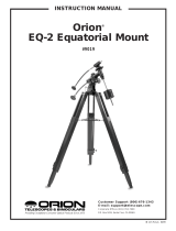
Tripod Leg Lock Knob
Tripod Spreader Lock Knob
Tripod Spreader
Mount Locking Knob and Shaft
Azimuth Adjustment Knob
Latitude Adjustment Knob
North Tripod Leg
Latitude Scale
Counterweight Shaft
Counterweight Shaft Safety Nut
Counterweight
Counterweight Locking Knob
Counterweight Shaft Locking Nut
DEC Setting Circle
RA Setting Circle (not shown)
RA Setting Circle Locking Knob
RA Clutch Locking Knob (see inset)
DEC Clutch Locking Knob
DEC Slow Motion Control Knob
RA Slow Motion Control Knob
Polar Scope Front Cap
Polar Scope Rear Cap
R.A. Motor Cover(R.A. motor not included)
OTA Dovetail Lock Knobs(see inset)
LX70 Mount Key Features
1
2
3
4
5
6
7
8
9
10
11
12
13
14
15
16
17
18
19
20
21
22
23
24
6
5
1
2
3
4
5
6
7
8
9
10
11
12
13
14
15
16
17
18
19
20
21
22
23
24
Figure 1: LX70 Key Features
DEC Axis
RA Axis
RA & DEC Axes
Mount Close-up
LX70 Telescope
24
17

5
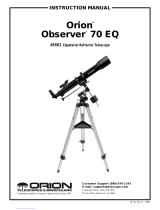
Front Dust Cover (not shown)
Dovetail Rail
Cradle Ring & Cradle Ring Lock Knobs
1/4-20 Accessory Mounting Screw with Lock
Focuser and Focuser Wheel
Focuser Lock Knob
Eyepiece
Eyepiece Holder Thumbscrews
Viewfinder
Viewfinder Dust Caps
Viewfinder Adjustment Screws
Viewfinder Bracket with Lock Knob
Optical Tube Assembly (OTA)
Objective Lens Cell
Dewshield
Diagonal Mirror
Diagonal Mirror Thumbscrews
LX70 OTA Key Features
27
28
29
30
31
32
33
34
35
36
37
38
39
40
Figure 2: LX70 Refractor Optical Tube
25
26
27
28
29
30
31
32
33
34
35
36
37
38
39
40
41
25
26
34
41
42
26
25
27
28
29
30
31
32
33
34
34
35
36
37
42
46
45
48
47
47
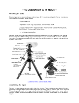
Figure 3: LX70 Reflector Optical Tube
Front Dust Cover (not shown)
Dovetail Rail
Cradle Ring & Cradle Ring Lock Knobs
1/4-20 Accessory Mounting Screw with Lock
Focuser & Focuser Wheel
Focuser Lock Knob
Eyepiece
Eyepiece Holder Thumbscrews
Viewfinder
Viewfinder Dust Caps
Viewfinder Adjustment Screws
Viewfinder Bracket with Lock Knob
Optical Tube Assembly (OTA)
Primary Mirror (see inset)
Primary Mirror Collimation Adjustment Knobs
Primary Mirror Collimation Lock Knobs
Spider Vane (see inset)
Spider Vane Tension Knobs
Secondary Mirror (see inset)
Secondary Mirror Collimation Screws (see inset)
25
26
27
28
29
30
31
32
33
34
35
36
42
43
44
45
46
47
48
37
44
4243
48
44
45
Front View Rear View

6
6
Front Dust Cover (not shown)
Dovetail Rail
Focuser Knob (not shown)
Eyepiece
Eyepiece Holder Thumbscrews
Viewfinder
Viewfinder Dust Caps
Viewfinder Adjustment Screws
Viewfinder Bracket with Lock Knob
Optical Tube Assembly (OTA)
Diagonal Mirror
Diagonal Mirror Thumbscrews
Extension Tube
Figure 4: LX70 Maksutov Optical Tube
25
29
31
32
33
34
35
36
37
49
26
25
26
40
41
29
31
32
3334
36
37
40
41
49
41
35
LX70 OTA Key Features

7
The Meade LX70 series models are versa-
tile, high-resolution telescopes. They offer un-
matched mechanical and optical performance
that reveal nature in an ever-expanding level of
detail. Observe the feather structure of an eagle
from 50 yards or study the rings of the planet
Saturn from a distance of 800 million miles. Fo-
cus beyond the Solar System and observe ma-
jestic nebulae, ancient star clusters, and remote
galaxies.
Meade LX70 series telescopes are instruments
fully capable of growing with your interest and
can meet the requirements of the most demand-
ing advanced observer. Before using your tele-
scope, read the entire instructions carefully. Your
telescope should be assembled during daylight
hours and setup in an area that allows you to
unpack all the included parts.
Unpacking and Assembly
1. Remove the components from the boxes:
Remove and identify the telescope’s equipment.
Refer to FIG. 1 - 4 for images of the parts and
the overall assembly of your telescope.
When removing the tripod from the box, hold the
assembly parallel (horizontal) to the ground or
the inner tripod leg extensions may slide out if
they are not locked in place. Tighten the tripod
leg lock knobs (Fig. 1. #1) to secure the legs in
place.
2. Adjust the tripod legs: Spread the tripod
legs as far apart as they will open. Now adjust
the individual tripod legs by loosening the tripod
leg lock knobs and extending the inner legs un-
til the tripod head is approximately level to the
ground. Relock the leg lock knob until firm.
3. Attach the spreader bar to the tripod:
Thread the small end of the Mount Locking
Knob and Shaft (Fig. 1, #4) along with the wash-
er all the way into the bottom of the tripod head.
When complete, the shaft will be held captive
and allowed to be raised above the threads.
Next, remove the Tripod Spreader Lock Knob
(Fig. 1, #2) and washer. Place the center hole of
the Tripod Spreader (Fig. 1, #3) onto the chrome
shaft with the flat side facing up. Loosely thread
on the Tripod Spreader Lock Knob and washer
to prevent the tripod spreader from falling off the
shaft.
4. Attach mount to tripod: Place the LX70
mount onto the tripod head with the protrusion
on top of the tripod’s head positioned between
the fine azimuth adjustment knobs (Fig 1, #5 ).
If necessary, back off the azimuth adjustment
knobs wide enough for the protrusion to fit be-
tween them.
Next, tighten the Mount Locking Knob (Fig. 1,
#4) so the mount secures to the tripod head.
Tighten this knob to a firm feel. Then rotate the
Tripod Spreader (Fig. 1, #3) so the wings of the
spreader align with each tripod leg. Tighten the
Tripod Spreader Lock Knob(Fig. 1, #2) until firm.
When you wish to collapse the tripod, loosen
the Tripod Spreader Lock Knob and rotate the
wings so they are between the tripod legs. You
do not need to remove the Tripod Spreader un-
less desired.
Figure 5: Installing the
mount locking knob and shaft
Figure 6: Tripod spreader
Figure 7: Attaching mount
to tripod
Figure 8: Tightening the spreader
lock knob
Getting Started

8
8
5. Attach the counterweight shaft: Locate
the counterweight shaft (Fig. 1, #9) and thread
down the Locking Nut (Fig. 1, #13) until it stops.
Next, thread the counterweight shaft into the
threaded hole on the front side of the mount,
below the declination setting circle (Fig. 1, #14).
Tighten to a firm feel. Adjust the Locking Nut
upward toward the mount until it stops. Tighten
to a firm feel.
6. Install the latitude adjusting screws: Lo-
cate the two threaded latitude knobs (Fig. 1, #6)
in the box. Thread the longer latitude adjust-
ment knob into the rear of the mount and the
shorter latitude adjustment knob into the front of
the mount as shown.
7. Set the latitude: Setting the latitude is easier
if it is set before you attach the optical tube and
counterweights. Locate the latitude dial (Fig. 1,
#8); note that there is a triangular pointer above
the dial located on the mount. The pointer is not
fixed; it moves as the mount moves.
Determine the latitude of your observing loca-
tion. See APPENDIX C: LATITUDE CHART
for a list of latitudes, or check the internet. Move
the latitude screws in order to move the mount
until the pointer points to your latitude. The
two latitude screws work in a “push - pull” op-
eration—as you tighten one, loosen the other.
When the pointer points at your latitude, tighten
both screws until they make contact with the
mount. At your observing site, set up the tele-
scope assembly so that the tripod leg below the
counterweight shaft, labeled “N”, (FIG. 1, #7)
approximately faces True North (or True South
in the Southern Hemisphere). For more infor-
mations see page 14 LOCATING THE CELES-
TIAL POLE.
8. Attach the slow motion control cables:
The LX70 comes equipped with flexible slow
motion control cables for both the RA & Dec
axes. Each cable is securely fastened on each
axis by a small Phillips head screw. Locate the
RA worm shaft mounting location and notice
that it has a flat portion on one side(see Fig 13).
Slide one of the cables onto the shaft so the
Phillips head locking screw is aligned with the
flat portion on the shaft. Using the included Phil-
lips screw driver, secure the slow motion control
cable onto the shaft until firm. Repeat this pro-
cess for the declination cable(see Fig 14).
9. Attach the counterweight(s): Look through
the hole in the counterweight (Fig. 1, #11) and
note the pin blocking the hole. Loosen the coun-
Figure 9: Attach the counter-
weight shaft
Figure 10: Set the latitude
Figure 13: Attach the RA
slow motion control cable
Figure 14: Attach the DEC
slow motion control cable
Figure 15: Remove the
safety nut
Figure 16: Install the counter-
weight
Figure 11: Latitude pointer
Figure 12: North tripod leg
Pointer
Pointer

9
terweight lock knob so the pin is not obstruct-
ing the hole. Unscrew the safety cap (Fig. 1,
#10) from the shaft. Holding the counterweight
firmly in one hand, slip the counterweight to ap-
proximately the midpoint of the counterweight
shaft. Tighten the counterweight lock knob(Fig.
1, #12) to a firm feel. Replace the safety cap.
Note: If the counterweight ever slips, the safety
cap prevents the counterweight from sliding en-
tirely off the shaft. Always leave the safety cap
in place when the counterweight is on the shaft.
10. Attach the optical tube: Before attaching
the optical tube, lock both the RA and DEC axes
(Fig. 1, #17 & 18) so the mount does not move
during installation. Verify the cradle ring lock
knobs (Fig. 2 or 3, #27) are tight and securely
fastened to the OTA. The cradle rings should be
roughly centered on the OTA during installation.
While firmly holding the optical tube with both
hands, slide the cradle assembly onto the cra-
dle mounting slot at the top of the mount(see
Fig 17).
Tighten both OTA dovetail lock knobs (Fig. 1,
#24) onto the dovetail rail (Fig. 2 - 4, #26) to a
firm feel. The cradle rings and OTA will now be
securely fastened to the mount.
After attaching all accessories to the OTA, you
will need to balance the telescope before use.
See the section BALANCING THE TELE-
SCOPE.
11. Assemble the viewfinder: Locate the view-
finder bracket. Carefully remove the rubber O-
ring from the bracket and position the O-ring
into the groove located approximately half-way
down the viewfinder tube(see Fig 18 & 19). Un-
screw the black alignment screws on the brack-
et and slide the viewfinder optical tube until the
O-ring seats into the bracket. One alignment
screw on the bracket is spring loaded to allow
easier alignment of the viewfinder. Pull out on
the spring loaded alignment screw to retract it,
allowing the viewfinder tube to fit properly into
the bracket. When the O-ring is properly seated
in the bracket, tighten the two alignment screws
to secure the viewfinder in place.
12. Attach viewfinder bracket: Slide the view-
finder bracket into its receiver on the OTA (Fig.
2 - 4, #36). To secure the viewfinder to the tele-
scope, tighten the viewfinder bracket lock knob
to a firm feel.
13. Insert the eyepiece:
Newtonian Reflector Models only (Fig 3):
Lift to remove the dust cap from the eyepiece
holder on the focuser assembly (Fig 3, #30). Set
the dust cap aside in a safe place and replace it
Figure 17: Tightening the dovetail lock knobs
Figure 18: Viewfinder parts
Figure 19: Installing the viewfinder
o-ring
Figure 20: Attaching the viewfinder bracket
Figure 21: Insert the 26mm eyepiece

10
10
when you have finished observing. Back off the
eyepiece thumbscrews (Fig 3, #32) and insert
the supplied eyepiece( Fig 3. #31) into the eye-
piece holder. Tighten the holder thumbscrews
to a firm feel to secure the eyepiece.
Note: Some models require an extension tube
(if included) be used to reach focus.
Achromatic Refractor only (Fig 2): Lift to re-
move the dust cap from the eyepiece holder on
the focuser assembly(Fig 2, # 30). Set the dust
cap aside in a safe place and replace it when
you have finished observing. Back off the eye-
piece thumbscrews (Fig. 2, #41) and slide the
diagonal(Fig. 2, #40) into the holder tightening
the thumbscrews to a firm feel only. Insert the
supplied 26mm eyepiece(Fig. 2, #31) into the
diagonal. Tighten the eyepiece holder thumb-
screws (Fig. 2, #32) to a firm feel to secure the
eyepiece.
Maksutov Models only (Fig 4): Lift to remove
the dust cap from the extension tube (Fig 4, #
49). Set the dust cap aside in a safe place and
replace it when you have finished observing.
Back off the diagonal mirror thumbscrews (Fig.
4, #41) and slide the diagonal(Fig. 4, #40) into
the holder and tighten the thumbscrews to a
firm feel only. Insert the supplied eyepiece(Fig.
4, #31) into the diagonal mirror. Tighten the eye-
piece holder thumbscrews(Fig. 4, #32) to a firm
feel to secure the eyepiece.
Balancing the Telescope
In order for the telescope to be stable on the
tripod and for it to move smoothly, it must be
balanced. To balance the telescope, unlock
the Right Ascension or R.A. lock (Fig 1, #17).
When this axis is unlocked, the telescope pivots
on the R.A. axis(see Fig. 1 inset). Later in the
procedure, you will also unlock the Declination
or Dec. lock (Fig. 1, #18).When unlocked, the
telescope pivots on the Dec. axis (see Fig 1 in-
set). Most of the motion of the telescope takes
place by moving about these two axes, sepa-
rately or simultaneously. Try to become familiar
with these locks and observe how the telescope
moves on each axis. To obtain a fine balance of
the telescope, follow the following method:
Figure 23: Insert the
eyepiece
Figure 22: Attach the diagonal
Figure 24: Attach the diagonal
Figure 25: Insert the
eyepiece
Figure 27: Balancing the DEC axis.
Adjust OTA or dovetail rail
Adjust OTA or dovetail rail
until balanced
until balanced
↔
↔
Figure 26: Balancing the RA axis
Adjust counterweights
Adjust counterweights
until balanced
until balanced
↔
↔

11
1. Firmly hold the counterweight shaft secure so
it cannot swing freely. Loosen the R.A. lock(Fig.
1, #17). The optical tube now moves freely about
the R.A. axis. Rotate the telescope so that the
counterweight shaft (Fig. 1, #9) is parallel (hori-
zontal) to the ground(see Fig. #26).
2. Unlock the counterweight lock knob and slide
the counterweight along the counterweight shaft
until the telescope remains in one position with-
out tending to drift down in either direction about
the RA axis. Then re-tighten the counterweight
lock knob, locking the counterweight securely in
position.
Now, hold the optical tube so that it cannot
swing freely. Lock the R.A. lock and while hold-
ing the OTA in place, unlock the Dec. lock (Fig.
1, #18). The OTA is now able to move freely
about the Dec. axis. Lightly loosen the cradle
ring lock knobs (Fig. 2 - 4, #27) so that the main
tube slides easily back and forth in the cradle
rings. Do not loosen the cradle ring lock knobs
too much or the OTA can slip out of the cradle
rings.
Move the main tube in the cradle rings until the
telescope remains in one position without tend-
ing to drift down in either direction. Re-lock the
Dec. lock (Fig. 2 - 4, #27).
The telescope is now properly balanced on both
axes. Next, the viewfinder must be aligned.
Aligning the Viewfinder
NEVER point the telescope directly at or near
the Sun at any time! Observing the Sun, even
for the smallest fraction of a second, will result
in instant and irreversible eye damage, as well
as physical damage to the telescope itself.
The wide field of view of the telescope’s
viewfinder(Fig. 2 - 4, #33) provides an easier
way to initially sight objects than the main tele-
scope’s eyepiece, which has a much narrower
field of view. If you have not already attached
the viewfinder to the telescope tube assembly,
see the section UNPACKING AND ASSEMBLY.
In order for the viewfinder to be useful, it must be
aligned to the main telescope, so both the view-
finder and telescope’s optical tube point at the
same position in the sky. This alignment makes
it easier to find objects: First locate an object in
the wide-field viewfinder, then look into the eye-
piece of the main telescope for a detailed view.
To align the viewfinder, perform steps 1 through
7 during the daytime; perform step 8 at night.
1. Remove the dust covers from the optical tube
and the viewfinder.
2. If you have not already done so, insert the
low-power 26mm eyepiece into the eyepiece
holder or diagonal of the main telescope.
3. Look through the viewfinder eyepiece at an
object at least 200 yards away.
4. If the distant object is not in focus, turn the fo-
cus lock ring on the front of the viewfinder coun-
terclockwise to loosen the viewfinder front lens
cell(see Fig. 28). Twist the front cell until focus is
achieved and retighten the focus lock ring.
5. Unlock the R.A. and Dec locks so the tele-
scope turns freely on both axes. Then point the
main telescope at a tall, well defined and sta-
tionary land object (e.g., the top of a telephone
pole) at least 200 yards distant and center the
object in the telescope’s eyepiece.
6. Focus the image by turning the OTA focus
knobs (Fig. 2 - 4, #29). Retighten the R.A. and
Dec. locks.
7. Look through the viewfinder and loosen or
tighten, as appropriate, one or both of the view-
finder alignment thumbscrews (Fig. 2 - 4, #35)
until the viewfinder’s crosshairs are precisely
centered on the object you previously centered
in the main telescope’s eyepiece. You are now
ready to make your first observations with your
telescope!
8. Check this alignment on a celestial object,
such as a bright star or the Moon, and make
any necessary refinements, using the method
Figure 28: Viewfinder adjustments
Focus Lock ring
Focus Lock ring
Front Lens Cell
Front Lens Cell
Alignment
Alignment
screws
screws

12
12
outlined above. With this alignment performed,
objects first located in the wide-field viewfinder
will also appear in the telescope’s eyepiece.
Choosing an Eyepiece
A telescope’s eyepiece magnifies the image
formed by the telescope’s main optics. Each
eyepiece has a focal length, expressed in mil-
limeters, or “mm.” The smaller the focal length,
the higher the magnification. For example,
an eyepiece with a focal length of 9mm has a
higher magnification than an eyepiece with a
focal length of 26mm. Your telescope comes
supplied with a 26mm eyepiece which gives a
wide, comfortable field of view with high image
resolution.
Low power eyepieces offer a wide field of view,
bright, high-contrast images, and eye relief
during long observing sessions. To find an ob-
ject with a telescope, always start with a lower
power eyepiece such as the 26mm. When the
object is located and centered in the eyepiece,
you may wish to switch to a higher power eye-
piece to enlarge the image as much as practical
for prevailing seeing conditions. For information
about optional eyepieces for the LX70 Series
models, see OPTIONAL ACCESSORIES.
The power, or magnification of a telescope is
determined by the focal length of the telescope
and the focal length of the eyepiece being
used. To calculate eyepiece power, divide the
telescope’s focal length by the eyepiece’s focal
length.
For example, a 26mm eyepiece is supplied with
the LX70 series. The focal length of the 8” re-
flector model is 1000mm.
Telescope Focal Length ÷ Eyepiece Focal Length = Mag-
nification (Power)
Telescope Focal Length = 1000mm
Eyepiece Focal Length = 26mm
1000 ÷ 26 = 38.46
The eyepiece power, or magnification is there-
fore 38X (approximately).
Can you ever have too much power? If the type
of power you’re referring to is eyepiece magni-
fication, yes, you can! The most common mis-
take of the beginning observer is to “overpower”
a telescope by using high magnifications which
the telescope’s aperture and atmospheric con-
ditions cannot reasonably support. Keep in mind
that a smaller, but bright and well-resolved im-
age is far superior to one that is larger, but dim
and poorly resolved.
Powers above 400X should be employed only
under the steadiest atmospheric conditions.
Most observers will eventually want three or
four additional eyepieces to achieve the full
range of reasonable magnifications possible
with the LX70 telescopes. See OPTIONAL AC-
CESSORIES.
Using the Bubble Level
For best telescope performance, the equatorial
mount should be properly leveled. A level tri-
pod allows better weight distribution and easier
alignment on the night sky. The LX70 mount in-
cludes a small bubble level near its base. Adjust
the height of each tripod leg until the bubble ap-
pears in the center of the circle.
Note: Adjusting the tripod on a fully assembled
mount can be dangerous. Get the assistance of
a friend if attempting to adjust the tripod height
while fully assembled.
Observing by Moving the
Telescope Manually
After the telescope is assembled and balanced
as described previously, you are ready to begin
manual observations. View easy-to-find terres-
trial objects such as street signs or traffic lights
to become accustomed to the functions and op-
erations of the telescope. For the best results
during observations, follow the suggestions be-
low:
When you wish to locate an object to observe,
first loosen the telescope’s R.A. lock and Dec.
lock. The telescope can now turn freely on its
axes. Unlock each axis separately and practice
moving your telescope. Then practice with two
unlocked axes at the same time. It is very im-
portant to practice this step to understand how
your telescope moves, as the movement of an
equatorial mount is not intuitive.
Use the aligned viewfinder (see ALIGNING
THE VIEWFINDER, pg 11) to sight-in on the
object you wish to observe. When the object is
centered in the viewfinder’s crosshairs, re-tight-

13
en the R.A. and Dec. locks.
Once centered, an object can be focused by
turning one of the knobs of the focusing mecha-
nism. Notice that when observing astronomical
objects, the field of view begins to slowly drift
across the eyepiece field. This motion is caused
by the rotation of the Earth on its axis. Objects
appear to move through the field more rapidly at
higher powers. See TRACKING OBJECTS for
detailed information on how you can counteract
the drift in the field of view.
Observe the Moon
Point your telescope at the Moon (note that the
Moon is not visible every night). The Moon con-
tains many interesting features, including cra-
ters, mountain ranges, and fault lines. The best
time to view the Moon is during its crescent or
half phase. Sunlight strikes the Moon at an an-
gle during these periods and adds a depth to the
view (see Fig 46). No shadows are seen during
a full Moon, making the overly bright surface to
appear flat and rather uninteresting. Consider
the use of a neutral density Moon filter when
observing the Moon. See OPTIONAL ACCES-
SORIES. Not only does it cut down the Moon’s
bright glare, but it also enhances contrast, pro-
viding a more dramatic image.
Tracking Objects
As the Earth rotates beneath the night sky, the
stars appear to move from East to West. The
speed at which the stars move is called the si-
dereal rate. You can track objects at this rate
by using the RA and DEC slow motion control
cables(Fig. 1, #19 and #20) on each axis. To
properly track night sky objects, it is best to per-
form a procedure called a polar alignment.
In the northern hemisphere the polar align-
ment requires pointing the mounts RA axis at
the north star Polaris as accurately as possible.
In the southern hemisphere the polar alignment
requires pointing at the southern celestial pole.
For using the telescope visually, high preci-
sion is not needed for the polar alignment. Only
when using the telescope for astrophotography
will higher precision for the polar alignment be
necessary.
To point at Polaris, start by aiming the north leg
of the tripod north. Adjust the latitude(Fig. 1, #6)
and azimuth(Fig. 1, #5) mount adjustments so
that you can see Polaris through the polar axis
view port(Fig. 1, #22).
An optional polar axis scope is available if a
higher precision alignment is desired. See OP-
TIONAL ACCESSORIES. Polaris will be po-
sitioned at an altitude equal to your observing
sites latitude. If you know your local latitude
simply adjust the front and back latitude adjust-
ment bolts until the indicator points to your local
latitude on the scale(Fig. 1, #8). To find your lo-
cal latitude you can consult a road map , look it
up on the Internet, or see Appendix C: LATI-
TUDE CHART.

14
14
Pointer
Pointer
Figure 29: Latitude Scale with pointer
Locating the Celestial Pole
In the northern Hemisphere, find the North Star
Polaris by facing North. To get basic bearings
at an observing location, take note of where the
Sun rises (East) and sets (West) each day. After
the site is dark, face North by pointing your left
shoulder toward where the Sun set. To precise-
ly point at the pole, find the North Star (Polaris)
by using the Big Dipper as a guide (See figure
below).
In the southern Hemisphere, you align the
mount to the southern celestial pole. To do this
it is necessary to reference star patterns since
the southern celestial pole has no nearby bright
stars. The closest bright star to the south celes-
tial pole is Sigma Octanis, which is about one
degree away. Using Sigma Octanis and other
bright stars will help you locate the pole.
Toward
Toward
True North
True North
Figure 30: RA Polar Axis
toward True North (Polaris)
Figure 31: RA Polar Axis
toward True North (Polaris)
Polaris
Little Dipper
Big Dipper
Cassiopeia
Figure 32 : Finding Polaris (North Star) For Northern
Hemisphere observers
Toward
Toward
True North
True North
(North Star)
(North Star)
Top View
Top View
Side
Side
View
View

15
Maintenance
General Maintenance
LX70-Series telescopes are precision optical
instruments designed to yield a lifetime of re-
warding views. Given the care and respect due
any precision instrument, your LX70 will rarely,
if ever, require factory servicing. Maintenance
guidelines include:
a. Avoid cleaning the telescope’s optics: A little
dust on the mirrors or the front surface of the
telescope’s lens causes virtually no degrada-
tion of image quality and should not be consid-
ered reason to clean the lens.
b. When absolutely necessary, dust on the mir-
rors or front lens should be removed with gentle
strokes of a camel hair brush or blown off with
an ear syringe (available at any pharmacy).
DO NOT use a commercial photographic lens
cleaner.
c. Organic materials (e.g., fingerprints) on the
front lens may be removed with a solution of
3 parts distilled water to 1 part isopropyl alco-
hol. You may also add 1 drop of biodegrad-
able dishwashing soap per pint of solution. Use
soft, white facial tissues and make short, gentle
strokes. Change tissues often. Caution: Do not
use scented or lotion tissues or damage could
result to the optics.
d. If the LX70 is used outdoors on a humid
night, water condensation on the telescope sur-
faces will probably result. While such conden-
sation does not normally cause any damage to
the telescope, it is recommended that the entire
telescope be wiped down with a dry cloth before
the telescope is packed away. Do not, however,
wipe any of the optical surfaces. Rather, simply
allow the telescope to sit for some time in the
warm indoor air, so that the wet optical surfaces
can dry unattended.
Inspecting the Optics
A Note about the Flashlight Test: If a flashlight or
other high-intensity light source is pointed down
the main telescope tube, the view (depending
upon the observer’s line of sight and the angle
of the light) may reveal what appears to be
scratches, dark or bright spots, or just generally
uneven coatings, giving the appearance of poor
quality optics. These items are only seen when
a high intensity light is transmitted through lens-
es or reflected off the mirrors, and can be seen
on any high quality optical system, including gi-
ant research telescopes. The optical quality of
a telescope cannot be judged by the “flashlight
test;” the true test of optical quality can only be
conducted through careful star testing.
Figure 33: Correct (1) and incorrect (2) collimation as viewed
during a star test
21

16
16
Alignment (Collimation) of
the Newtonian Reflector OTA
The optical systems of Newtonian Reflector
telescopes include the following parts: primary
mirror (Fig. 34, #1); secondary mirror (Fig. 34,
#2); secondary mirror-holder (Fig. 34, #3); sec-
ondary mirror-vanes (Fig. 34, #4) and (Fig. 35,
#1); primary mirror-tilt screws (Fig. 34, #5). The
telescope’s image is brought to a focus at (Fig.
34, #6).
1. Confirm alignment - To confirm optical
alignment look down the focuser drawtube (Fig.
37, #1) with the eyepiece removed. The edge of
the focuser drawtube frames reflections of the
primary mirror (Fig. 37, #2), the secondary mir-
ror (Fig. 37, #3), the four (“spider”) vanes (Fig.
37, #4) holding the secondary mirror, and the
observer’s eye (Fig. 37, #5). With the optics
properly aligned, all of these reflections appear
concentric (centered), as shown in Fig. 37. Any
deviation from concentricity of any of these tele-
scope parts with the eye requires adjustments
to the secondary mirror-holder (Fig. 35) and/or
the primary mirror cell (Fig. 36), as described
below.
2. Secondary mirror-vane adjustments: If the
secondary mirror (1, Fig. 38) is left or right of
center within the drawtube (Fig. 38, #2), slightly
loosen the 3 collimation screws on the top of
the secondary mirror holder (Fig. 35, #2). Next,
tighten or loosen as necessary, the central
Phillips screw to center the secondary mirror
position in the focuser draw tube. When cor-
rectly positioned, lightly tighten the 3 collima-
tion screws (Fig. 35, #2) until they touch the top
of the secondary mirror. The secondary mirror
should now be centered in the focuser drawtube
left or right. If the secondary mirror (Fig. 38, #1)
is above- or below-center within the drawtube,
thread inward one of the adjustment/lock knobs
(Fig. 35, #1) while unthreading another of these
knobs. Only make adjustments to two knobs at
a time until the secondary mirror appears as in
Fig. 39.
3. Secondary mirror-holder adjustments: If
the secondary mirror (Fig. 39, #1) is centered
in the focuser drawtube (Fig. 39, #2), but the
primary mirror is only partially visible in the re-
flection (Fig. 39, #3), the three secondary mirror
collimation screws (Fig. 35, #2) should be slight-
ly unthreaded to the point where the secondary
mirror-holder (Fig. 35, #3) can rotate about its
axis parallel to the main tube. Grasp the sec-
ondary mirror-holder (avoid touching the mir-
ror surface!) with your hand and rotate it until,
looking through the drawtube, you can see the
primary mirror centered as well as possible in
the reflection of the secondary mirror. With the
rotation of the secondary mirror-holder at this
best-possible position, thread in the three sec-
ondary collimation screws (Fig. 35, #2) to lock
the rotational position. Then, if necessary, make
adjustments to these three collimation screws
to refine the tilt-angle of the secondary mirror,
until the entire primary mirror can be seen cen-
tered within the secondary mirror’s reflection.
With the secondary mirror thus aligned the im-
age through the drawtube appears as in Fig. 40.
4. Primary mirror adjustments: If the second-
ary mirror (Fig. 40, #1) and the reflection of the
primary mirror (Fig. 40, #2) appear centered
within the drawtube (Fig. 40, #3), but the reflec-
tion of your eye and the reflection of the sec-
ondary mirror (Fig. 40, #4) appear off-center,
then the primary mirror tilt requires adjusting,
using the Phillips head screws of the primary
mirror cell (Fig. 36, #3). These primary mirror-tilt
screws are located behind the primary mirror,
at the lower end of the main tube. See Fig. 36.
Before adjusting the primary mirror-tilt screws,
first unscrew by several turns the three long
primary mirror lock screws (Fig. 36, #2) which
are also located on the rear surface of the pri-
mary mirror cell and which alternate around the
cell’s circumference with the three long and thin
thumbscrews. These lock screws do not have
springs beneath them. Then by trial and error
turn the primary mirror tilt thumbscrews (Fig. 36,
#3) until you develop a feel for which way to turn
each screw to center the reflection of your eye
in the drawtube. (An assistant is helpful in this
operation.) With your eye centered as shown in
Fig. 37, turn the three long and thin mirror lock
screws (Fig. 36, #2) to re-lock the tilt-angle of
the primary mirror.
5. The telescope’s optical system is now aligned,
or collimated. This collimation should be re-
checked from time to time, with small adjust-
ments (per steps 1, 2, and/or 3, above) effected
as required to keep the optics well-aligned.

17
Figure 34
Figure 36
Figure 37
Figure 38
Figure 39
Figure 40
12
3
4
5
1
2
3
2 3
1
2
34
5
1
2
3
4
Figure 35
6
2
1
2
1
2
3
Newtonian Refl ector (section view)
Newtonian Refl ector (section view)

18
18
OPTIONAL ACCESSORIES
A wide assortment of professional Meade acces-
sories is available for the LX70 Series telescope
models. The premium quality of these accessories
is well-suited to the quality of the instrument itself.
Consult the Meade Website (www.meade.com) for
complete details on these and other accessories.
#670010 LX70 Polar Scope: The Meade LX70
Polar scope is designed to assist the user in per-
forming a polar alignment on the night sky. The
polar scope includes a reticule pattern which is
used in the alignment process, making the LX70
polar scope even more user friendly. As a result,
the LX70 mount can be aligned with a higher preci-
sion and allows the user to more quickly enjoy the
night sky. See the Meade website for more details.
#670011 LX70 Motor Drive Kit: The LX70 mo-
tor drive kit attaches to both telescope axes. The
motor drive kit allows tracking of celestial objects
at the speed of the earth’s rotation. The included
hand controller is used to adjust the mount when
using the mount for astrophotography. Use of the
LX70 motor drive kit requires the LX70 mount to
be properly polar aligned on the night sky. See the
Meade website for more details.
Laser Collimator: Meade’s Laser collimator helps
make collimation of Newtonian telescopes quick
and easy. Collimation is a method to align your
telescope’s optics. Your telescope is aligned at the
factory, but shipping and handling can sometimes
mis-align collimation. Misaligned collimation can
mean dimmer and blurrier images in your tele-
scope eyepiece. Make collimation quick and easy
with a Meade laser collimator.
Series 4000 8 - 24mm Zoom Eyepiece: The inter-
nal zoom optics of this eyepiece move on smooth,
precisely machined surfaces which maintain opti-
cal collimation at all zoom settings. A scale gradu-
ated in 1mm units indicates the zoom focal length
in operation. An excellent addition to any eyepiece
set.
#140 2x Barlow Lens: A 3-element design, dou-
bles each eyepiece power while maintaining un-
compromised image resolution, color correction,
and contrast. Insert the #140 into the telescope’s
eyepiece holder first, followed by the diagonal
(as applicable) and eyepiece. The #126 2x Bar-
low Lens, a compact 2-element alternative to the
#140, may also be employed with any LX70 Se-
ries telescope.
#905 Variable Polarizer (1.25”): The #905 sys-
tem includes 2 Polarizer filters mounted in a spe-
cially-machined cell, for glare-reduction in observ-
ing the Moon. Rotate the thumbscrew at the side
of the unit to achieve light transmission between
5% and 25% of its original value. The #905 inserts
into the diagonal of the telescope, followed by an
eyepiece.
Series 4000 Photo-Visual Color Filters: Color fil-
ters significantly enhance visual and photographic
image contrast of the Moon and planets. Each fil-
ter threads into the barrel of any Meade 1.25” eye-
piece, and into the barrels of virtually all other eye-
piece brands as well. Meade filters are available in
12 colors for lunar and planetary applications, and
in Neutral Density as a lunar glare-reduction filter.
Series 4000 Nebular Filters: A modern boon to
the city-dwelling deep-space observer, the inter-
ference nebular filter effectively cancels out the
effects of most urban light pollution, while leaving
the light of deep-space nebular emissions virtually
un-attenuated. Meade Series 4000 Nebular Filters
utilize the very latest in coating technology, and
are available with threaded cells for eyepieces or
for attachment to the rear cells of Meade ACF tele-
scopes.
#91101 Meade LED Flashlight: The LED flash-
light features a very bright beam from 16 LED’s
and is push button selectable from white for nor-
mal illumination to red to preserve night vision.
Heavy duty metal construction, with threaded bat-
tery compartment. (3 “AAA” batteries required.)
Meade Series 4000 Eyepiece and Filter Set:
Complete set of the most popular accessories.
Includes six popular Meade Series 4000 Su-
per Plossl Eyepieces in focal lengths of 6.4mm,
9.7mm, 12.4mm, 15mm, 32mm and 40mm. All
eyepieces feature a standard 1.25” barrel size,
with a 52° apparent field of view and are of a 4-el-
ement design with premium optical glass. This this
kit also contains a Meade Series 4000 Color Fil-
ter Set #1 including high quality “dyed in glass”
#12 Yellow, #23 Light Red, #58 Green and # 80A
Blue filters which are very useful for bringing out
various details on the planets. There is also a Se-
ries 4000 ND96 Moon Filter to reduce glare and
increase clarity when observing the Moon.
To find out more about these and other accessories
available for your telescope, check out the Meade
website or contact your local Meade dealer.

19
APPENDIX A:
Celestial Coordinates
A celestial coordinate system was created that
maps an imaginary sphere surrounding the
Earth upon which all stars appear to be placed.
This mapping system is similar to the system of
latitude and longitude on Earth surface maps.
In mapping the surface of the Earth, lines of lon-
gitude are drawn between the North and South
Poles and lines of latitude are drawn in an East-
West direction, parallel to the Earth’s equator.
Similarly, imaginary lines have been drawn to
form a latitude and longitude grid for the celes-
tial sphere. These lines are known as Right As-
cension and
Declination.
The celestial map also contains two poles and
an equator just like a map of the Earth. The
poles of this coordinate system are defined as
those two points where the Earth’s north and
south poles (i.e., the Earth’s axis), if extended to
infinity, would cross the celestial sphere. Thus,
the North Celestial Pole (1, Fig. 41) is that point
in the sky where an extension of the North Pole
intersects the celestial sphere. The North Star,
Polaris is located very near the North Celestial
Pole. The celestial equator (2, Fig. 41) is a pro-
jection of the Earth’s equator onto the celes-
tial sphere. Just as an object’s position on the
Earth’s surface can be located by its latitude and
longitude, celestial objects may also be located
using Right Ascension and Declination. For ex-
ample, you could locate Los Angeles, California,
by its latitude (+34°) and longitude (118°). Simi-
larly, you could locate the Ring Nebula (M57)
by its Right Ascension (18hr) and its Declination
(+33°).
Right Ascension (R.A.): This celestial version
of longitude is measured in units of hours (hr),
minutes (min), and seconds (sec) on a 24-hour
“clock” (similar to how Earth’s time zones are
determined by longitude lines). The “zero” line
was arbitrarily chosen to pass through the con-
stellation Pegasus — a sort of cosmic Green-
wich meridian. R.A. coordinates range from 0hr
0min 0sec to 23hr 59min 59sec. There are 24
primary lines of R.A., located at 15-degree inter-
vals along the celestial equator. Objects located
further and further East of the zero R.A. grid line
(0hr 0min 0sec) carry higher R.A. coordinates.
Declination (Dec.): This celestial version of lat-
itude is measured in degrees, arc-minutes, and
arc-seconds (e.g., 15° 27’ 33”). Dec. locations
north of the celestial equator are indicated with
a plus (+) sign (e.g., the Dec. of the North ce-
lestial pole is +90°). Dec. locations south of the
celestial equator are indicated with a minus (–)
sign (e.g., the Dec. of the South celestial pole is
–90°). Any point on the celestial equator (such
as the constellations of Orion, Virgo, and Aquar-
ius) is said to have a Declination of zero, shown
as 0° 0’ 0.”APPENDIX B: Setting Circles
Setting circles permit the location of faint ce-
lestial objects not easily found by direct visual
observation. With the telescope pointed at the
North Celestial Pole, the Dec. circle (see Fig.
43) should read 90° (understood to mean +90°).
Each division of the Dec. circle represents a 1°
increment. The R.A. circle (see Fig. 42) runs
from 0hr to (but not including) 24hr, and reads in
increments of 10 minutes. Using setting circles
requires a developed technique. When using
the circles for the first time, try hopping from one
bright star (the calibration star) to another bright
star of known coordinates.
Practice moving the telescope from one easy-to-
find object to another. In this way, the precision
required for accurate object location becomes
evident.
14
15
16
17
18
19
20
21
22
23
0
1
12
11
10
9
8
7
5
6
4
3
2
13
Earth’s
Rotation
0 Dec.
South
Celestial
Pole
Right Ascension
Star
Celestial
Equator
-90 Dec.
+90 Dec.
North
Celestial
Pole
(Vicinity
of Polaris)
D
e
c
l
i
n
a
t
i
o
n
1
2
Figure 41: Celestial Sphere

20
20
APPENDIX B:
Setting Circles
To use the setting circles to locate an object not
easily found by direct visual observation:
Insert a low-power eyepiece, such as a 26mm,
into the focuser assembly. Pick out a bright star
with which you are familiar (or is easily located)
that is in the area of the sky in which your target
object is located. Look up the R.A. coordinate of
the bright star, and also of the object you wish
to locate, in a star atlas or on the internet. Point
the telescope at the bright star. Then loosen the
R.A. setting circle lock knob (see Fig. 42) and
turn the R.A. setting circle to read the correct
R.A. coordinate of the bright star; lock the R.A.
setting circle lock knob to secure the setting
circle in place (If you are in the northern hemi-
sphere, use the top numbers on the RA setting
circle. If you are in the southern hemisphere use
the bottom numbers.). Next, adjust the DEC set-
ting circle by moving the setting circle ring until
the objects DEC coordinate is aligned with the 0
registration mark. If the procedure has been fol-
lowed carefully, the bright star should now be in
the center of the telescope eyepiece and setting
circles showing the bright star coordinates.
To locate another object, unlock the RA and
DEC locks and move the telescope so the RA
and DEC setting circle coordinates match the
target object. Then lock each axis and use the
slow motion controls to track the object.
If when using the setting circles to locate ob-
jects, you do not immediately see the object
you are seeking, try searching the adjacent sky
area. Start with the 26mm eyepiece when locat-
ing object since it has a wider field of view than
the 9mm. Because of its much wider field, the
viewfinder may be of significant assistance in
locating and centering objects, after the setting
circles have been used to locate the approxi-
mate position of the object.
Figure 43: DEC setting circleFigure 42: RA setting circle and lock knob
RA Setting Circle
RA Setting Circle
Lock Knob
Lock Knob
DEC Setting Circle
DEC Setting Circle
RA Setting Circle
RA Setting Circle
/