
PI200 User Guide
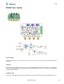
Power supply
You need to supply +5 V on the +Vcc pin and -5 V on the -Vcc pin. Do not apply any voltage outside this range on
the board.
Setpoint
Setpoint can be adjusted between -2.5 V and +2.5 V with the SETPOINT trimmer. The setpoint can be modulated
with the SETPOINT MOD input. Modulation input is DC coupled, gain is 1 V/V, 0.1 V/V or 0.01 V/V, depending
on the MOD GAIN jumper.
Feedback sign
The sign of the feedback for FAST OUT and SLOW OUT can be chosen with the FAST and SLOW jumpers (+1 or -
1 / 2
PI200
www.koheron.com

1).
Integrator enable
FAST and SLOW integrators are enabled with the INT EN switch ON. When the switched are OFF, the integrators
can still be enabled by applying logic high signals on the FAST INT EN / SLOW INT EN pins.
Ramp in
A modulation can be added to the output of the slow integrator SLOW OUT via the RAMP IN pin.
Input / Output ranges
Input range is ±3 V on the IN and SETPOINT MOD inputs. Output range is ±3 V in the ERROR, FAST_OUT and
SLOW_OUT outputs.
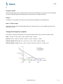
Tuning the frequency response
The frequency response of the loop filter can be adjusted with the 3 blue rotary switches in clockwise order:
PROP: -13.3 dB / -6.6 dB / 0 dB / 6.6 dB / 13.3 dB / 20 dB / 26.6 dB.
FAST INT: 47 kHz / 100 kHz / 220 kHz / 470 kHz / 1 MHz / 2.2 MHz / 4.7 MHz.
SLOW INT (PI200 version): 800 mHz / 2.4 Hz / 8 Hz / 24 Hz / 80 Hz / 240 Hz / 800 Hz.
SLOW INT (PI200-T version) : 8 mHz / 24 mHz / 80 mHz / 240 mHz / 800 mHz / 2.40 Hz / 8 Hz.
2 / 2
PI200
www.koheron.com
-
 1
1
-
 2
2


Ask a question and I''ll find the answer in the document
Finding information in a document is now easier with AI
Other documents
-
Peach 312379 Datasheet
-
Caraudio Systems CX-025 Installation guide
-
-
-
-
-
Danfoss AK-SM 800 AK-System Manager. Installation guide
-
Renishaw IS1-2 Installation guide
-
Tait TP9100 User manual
-
Renishaw Autochange system Installation guide