Page is loading ...

TM-2012/3012 AC CLAMP METER
TM-2013/3014 AC/DC CLAMP METER
User’s manual
TENMARS ELECTRONICS CO., LTD
HB2TM2012001

TM- 2012/2013/3012/3014
EN - 2
CONTENTS:
1. SAFETY PRECAUTIONS AND PROCEDURES ..........................4
2. THE FOLLOWINGS SYMBOLS ARE USED: ...............................5
2.1. Preliminary...................................................................................... 5
2.2. During Use ...................................................................................... 6
2.3. After Use......................................................................................... 7
2.4. DEFINITION OF MEASURING (OVERVOLTAGE) CATEGORY
……………………………………………………………………..7
3. GENERAL DESCRIPTION............................................................8
4. PREPARATION FOR USE............................................................9
4.1. Initial............................................................................................... 9
4.2. Supply Voltage ................................................................................ 9
4.3. Calibration....................................................................................... 9
4.4. Storage .......................................................................................... 10
5. OPERATING INSTRUCTIONS ...................................................10
5.1. Instrument Description.................................................................. 10
5.1.1. Commands description...................................................10
5.1.2. Alignment marks.............................................................11
5.1.3. AUTO POWER OFF function .........................................12
5.2. Function key description............................................................... 12
5.2.1. RANGE key: range selection..........................................12
5.2.2. ZERO relative function ...................................................12
5.2.3. HOLD key: HOLD function .............................................13
5.2.4. Backlight display and work light for easy reading in the
dark. ..........................................................................................13
5.2.5. MAX/MIN function ..........................................................13
6. TRUE RMS MEASUREMENT.....................................................14
7. INRUSH CURRENT ....................................................................14

TM- 2012/2013/3012/3014
EN - 3
8. WAVEFORM COMPARISON......................................................15
9. DESCRIPTION OF ROTARY SWITCH FUNCTIONDC..............16
9.1. dc CURRENT (DCA) measurement of (TM-3014/TM-2013) ..... 16
9.2. AC Current (ACA) measurement.................................................. 17
9.3. AC Voltage (ACV) measurement.................................................. 19
9.4. DC Voltage (DCV) measurement.................................................. 20
9.5. RESISTANCE MEASUREMENT ............................................... 21
9.6. DIODE MEASUREMENT........................................................... 22
9.7. CONTINUITY MEASUREMENT............................................... 23
9.8. Frequency measurements.............................................................. 24
10. ADP MEASUREMENTS.........................................................25
11. CAPACITANCE MEASUREMENTS.......................................26
12. PREVENTIVE MAINTENANCE..............................................28
12.1. General information ...................................................................... 28
13. BATTERY REPLACEMENT ...................................................28
14. CLEANING .............................................................................29
15. CHARACTERISTICS SPECIFICATIONS...............................29
16. SAFETY..................................................................................32
17. GENERAL DATA....................................................................33
18. ENVIRONMENTAL CONDITIONS .........................................34
18.1.1.Climatic conditions .........................................................34
19. EMC........................................................................................34
20. STANDARD ACCESSORIES.................................................34
21. END OF LIFE .........................................................................34

TM- 2012/2013/3012/3014
EN - 4
1. SAFETY PRECAUTIONS AND PROCEDURES
This apparatus conforms to safety standard EN 61010, relating
to electronic measuring instruments. For your own safety and
that of the apparatus, you must follow the procedures described
in this instruction manual and especially read all the notes
proceeded by the symbol carefully.
WARNING
If instrument is used in way don’t conform to
prescriptions of this user’s manual, all considered
safety protection maybe damaged.
Take extreme care for the following conditions when measuring:
• Do not measure voltage, current under humid or wet
environment.
• Do not operate the meter under the environment with
explosive gas (material), combustible gas (material), steam or
filled with dust.
• Keep you insulated from the object waiting for measuring.
• Do not contact any exposed metal (conductive) parts such as
end of test lead, socket, fixing object, circuit, etc.
• If any unusual condition of testing end (metal part) and
attachment of the meter such as breakage, deformation,
fracture, foreign substance, no display, etc., do not conduct
any measuring.
• Measuring voltage over 20V as it might cause human body
electricity conduction.
Take care not to allow your hand to pass over the Safety Guard
(see Fig.1, pos.2) on current measurements and voltage
measurements using the holster

TM- 2012/2013/3012/3014
EN - 5
2. THE FOLLOWINGS SYMBOLS ARE USED:
Ground
Meter Double insulated
Caution
Danger high voltage: risk of electric shock
DC Voltage or Current
AC Voltage or Current
DC/AC Voltage or Current
Application around and removal from hazardous
live conductors is permitted.
2.1. PRELIMINARY
• This apparatus has been designed for use in an environment
of pollution degree 2.
• It can be used for CURRENT and VOLTAGE measurements
on installations of surge voltage category CAT IV 600 V, CAT
III up to 1000 voltage between Phase and Earth (fixed
installations) and for current measures up to CATIII
1000V/660A and CAT IV 600V/660A for (TM-2012/2013) and
CAT III 1000V/1200A CATIV 600V/1200A for (TM-3012/TM-
3014)。
• This meter is not available for non-sine wave AC signal.
• You must comply with the usual safety regulations aimed at:
♦ Protecting you against the dangerous electric current.
♦ Protecting the instrument against an incorrect operation.
• Only the leads supplied with the instrument guarantee
compliance with the safety standard. They must be in a good
condition and they must be replaced, if necessary with an
identical model.
• Do not test or connect to any circuit with voltage or current
exceeding the specified overload protection.

TM- 2012/2013/3012/3014
EN - 6
• Do not perform any test with environmental condition
exceeding the limits indicated in paragraphs 13.1.1
• Check if the batteries are installed correctly.
• Prior to connecting the test probes to the installation, check
that the function selector is positioned on the required
measurement.
• Check if the LCD and the range indicator show the same as
the function desired.
2.2. DURING USE
Read the recommendation which follow and the instruction in
this manual:
WARNING
Non-compliance with the warnings and/or the
instructions for use may damage the apparatus
and/or its components or injure the operator.
• When changing range, first remove the tested conductor or
electrical circuit from the clamp jaw in order to avoid any
accident.
• When the apparatus is connected to the measuring circuits,
never touch an unused terminal.
• When measuring resistor, please do not add any voltage.
Though there is a protection circuit, excessive voltage will still
cause malfunction.
• When measuring current, first remove the test leads of
common and voltage-resistance.
• When measuring current, any strong current nears or closes
to the clamp jaw will affect the accuracy.
• When measuring current, always put the tested conductor in
the center of the clamp jaw so as to obtain a more accurate
reading as referred into paragraph 5.1.2.
• During measuring, if the value of reading or indications of
sign remain unchanged, check if the HOLD function is active.

TM- 2012/2013/3012/3014
EN - 7
2.3. AFTER USE
• Once the measurements are completed, turn the rotary
switch to OFF.
• If the instruments is not be used for a long period, remove the
battery.
2.4. DEFINITION OF MEASURING (OVERVOLTAGE)
CATEGORY
The norm EN 61010: Safety requirements for electrical
equipment for measurement,
Control and laboratory use, Part 1: General requirements,
defines what a measuring
Category, usually called over voltage category, is.
Circuits are divided into the following measurement categories:
z Measurement category IV is for measurements performed
at the source of the low-voltage installation.
Examples are electric meters and measurements on primary
over current protection devices and ripple control units.
z Measurement category III is for measurements performed
in a building installation.
Examples are measurements on distribution boards, circuit
breakers, wiring, including cables, bus-bars, junction boxes,
switches, switches, socket-outlets in the fixed installation,
and equipment for industrial use and some other equipment,
for example, stationary motors with permanent connection to
fixed installation.
z Measurement category II is for measurements performed
on circuits directly connected to the low voltage installation.
Examples are measurements on household appliances,
portable tools and similar equipment.
z Measurement category I is for measurements performed
on circuits not directly connected to MAINS.
Examples are measurements on circuits not derived from
MAINS, and specially protected (internal) MAINS-derived
circuits. In the latter case, transient stresses are variable; for

TM- 2012/2013/3012/3014
EN - 8
that reason, the norm requires that the transient withstand
capability of the equipment is made known to the user.
3. GENERAL DESCRIPTION
Dear customer, we thank you for your patronage. The clamp
you have just purchased will grant you accurate and reliable
measurements provided that it is used according to the present
manual’s instructions.
Thanks to a new development concept assuring double
insulation as well as compliance with category III up to 600V
you can rely on utmost safety conditions.
The apparatus can perform the following measurements:
• AC current (IAC).
• AC voltage (VAC).
• DC voltage (VDC).
• Resistance.
• Continuity Test.
• Diode test.
Each of these parameters can be selected by means of a 7-
position rotary switch, including an OFF position. There are also
the following keys: “D-H” and “R-H”. For their use please see
paragraph 5.2.
The selected quantity appears on a high-contrast display with
indication of measurement units and functions.

TM- 2012/2013/3012/3014
EN - 9
4. PREPARATION FOR USE
4.1. INITIAL
All the equipment has been checked mechanically and
electrically prior to shipment.
Every care has been taken to ensure that the instrument
reaches you undamaged.
However, it is wise to carry out a rapid check in order to detect
any possible damage, which might have been caused during
transport. Should this be the case, immediately enter the usual
claims with courier.
Check the packaging contained according to packaging list
reported in paragraph 15 In case of discrepancies contact the
dealer.
In the event of re-shipment of the equipment please follow the
instructions reported in paragraph.
4.2. SUPPLY VOLTAGE
The instrument is battery supplied; it use two batteries model
9V NEDA 1604 IEC 6F22 JIS 006P battery included in
packaging. The batteries autonomy is about 200 hours.
The symbol " " appears when the batteries are nearly
discharged. In case replace them following the instructions in
paragraph 13.
4.3. CALIBRATION
The instrument fulfils the technical characteristics listed in this
manual. The performance of the specifications is guaranteed for
one year.

TM- 2012/2013/3012/3014
EN - 10
4.4. STORAGE
In order to guarantee the accuracy of the measurements, after
a period of storage in extreme environment condition, wait for
the time necessary so that the apparatus returns to normal
measuring conditions (see environments specifications
paragraph 18.1.1.
5. OPERATING INSTRUCTIONS
5.1. INSTRUMENT DESCRIPTION
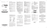
5.1.1.Commands description
1. Inductive clamp jaw. 2. Work light.
3. HOLD key. 4. Jaw Trigger.
5. Rotary switch Selector. 6. Backlight and Work light
key.
7. Inrush/select key. 8. Relative /ZERO key.
9. MAX/MIN key.
10. COM Jack: it is used for
the connection of negative
signal input while measuring
DCV、ACV、HZ、、、
、CX、ADP.
11. V/ Jack: It is used
for the connection of
positive signal input
while measuring DCV、
ACV、HZ、、、
、CX、ADP.

TM- 2012/2013/3012/3014
EN - 11
Fig. 1: Instrument description
5.1.2.Alignment marks
Put the conductor within the jaws on intersection of the
indicated marks as much as possible (see Fig. 2) In order to
meet the meter accuracy specifications.
LEGEND:
1. Alignment marks.
2. Conductor.
Fig. 2: Alignment marks

TM- 2012/2013/3012/3014
EN - 12
5.1.3.AUTO POWER OFF function
1. In order to save the battery the clamp will be switched off 30
minutes later last selecting
a function or changing range operation.
2. If this function is enabled the symbol is displayed.
3. To disable this function select OFF position then rotate the
selector in any position while the REL key is pressed. Turning
OFF and ON the clamp the AUTO POWER OFF will be re-
enabled.
5.2. FUNCTION KEY DESCRIPTION
5.2.1.RANGE key: range selection
Pressing the RANGE key you can switch between the
Automatic or Manual Range selection.
In particular the "MANU" symbol point out the Manual range
selection while the "AUTO" symbol point out the Automatic
Range selection.
The Manual Range selection will be disable if:
• The RANGE key is pressed more than 2 second.
• The position of the rotary switch is changed.
5.2.2.ZERO relative function
The ZERO relative function subtracts an OFFSET (stored
when the key has been pressed) from the present
measurements and displays the result.
To enable this function press the ZERO key for less than 1
second. Consequently on the display will appear the
message "ZERO" and the relative value.
Pressing the ZERO key again for less than 1 second the
display will show the offset; and the message "ZERO" start
blinking.
The ZERO relative function will be disable if:
The ZERO key is pressed more than 2 second.
The position of the rotary switch is changed.

TM- 2012/2013/3012/3014
EN - 13
This function can’t be enabled if the functions HOLD are
already selected.
Pressing the ZERO key the instrument will automatically set
the MANUAL Range selection.
5.2.3.HOLD key: HOLD function
The HOLD function allows operator to hold the displayed
digital values. When this function is enabled the display
shows the "H" symbol.
The HOLD function will be disabled if:
The HOLD key is pressed again.
The position of the rotary switch is changed.
The analogy barograph isn’t affected of enabling of this
function so it continues showing present readings.
The HOLD function will be disabled if:
The HOLD key is pressed again.
The position of the rotary switch is changed.
5.2.4.Backlight display and work light for easy reading in
the dark.
Press button for more than 1 second to toggle backlight and
work light ON/OFF. Back light and work light turns off
automatically after 15 seconds.
5.2.5.MAX/MIN function
By pressing MX/MN key, maximum and minimum values are
measured. Both values are stored and can be recalled by
pressing the same key. The symbol corresponding to the
desired function is displayed: “MAX” for maximum value,
“MIN” for minimum value. MX/MN key is disabled when
HOLD function is active. To exit this function keep MX/MN
key pressed for at least 1 second or rotate the selector to
another position.

TM- 2012/2013/3012/3014
EN - 14
6. TRUE RMS MEASUREMENT
The meter measures the true RMS value of AC voltages
and currents. In physical terms, the RMS (root-mean-square)
value of a waveform is the equivalent DC value that causes the
same amount of heat to be dissipated in a resistor. True RMS
measurement greatly simplifies the analysis of complex AC
signals. Since the RMS value is the DC equivalent of the
original waveform, it provides a reliable basis for comparing
dissimilar waveforms.
By contrast, many meters use average-responding AC
converters rather than true RMS converters. The scale factor in
these meters is adjusted so that they display the RMS value for
a harmonic-free sine wave. However, if a signal is not
sinusoidal, average-responding meters does not display correct
RMS readings.
7. INRUSH CURRENT
Inrush current refers to the maximum, instantaneous input
current drawn by an electrical device when first turned on. For
example, incandescent light bulbs have high inrush currents
until their filaments warm up and their resistance increases.
Alternating current electric motors and transformers may draw
several times their normal full-load current when first energized,
for a few cycles of the input waveform. Power converters also
feature high inrush currents relative to their steady state
currents. This is typically the charging current of the input
capacitance. The selection of overcorrect protection devices
such as fuses and circuit breakers is made more complicated
when high inrush currents must be tolerated. The overcorrect
protection must react quickly to overload or short circuit but
must not interrupt the circuit when the inrush current flows

TM- 2012/2013/3012/3014
EN - 15
8. WAVEFORM COMPARISON
Table 1.illustrates the relationship between AC and DC
components for common waveforms, and compares readings
for true RMS meters and average-responding meters. For
example, consider the first waveform, a 1.414V (zero-to-peak)
sine wave. Both the RMS-calibrated average-responding
meters display the correct RMS reading of 1.000V(the DC
component equals 0). However, consider the 2V (peak-to-peak)
square wave. Both types of meter correctly measure the DC
component (0V), but your also correctly measures the AC
component (1.000V) The average-responding meter measures
1.111V, which amounts to an 11% error.
Table 1. WAVEFROM COMPARISON CHART
Metered Voltages
Peak Value
AC
Components
only
Total RMS
AC coupled
Input
Waveform
Peak
-
Peak
0-Peak RMS
CAL
(*)
27E
DC
components
only TRUE RMS
22
DCAC +
Sine
2.828 1.414 1.000 1.000 0.000 1.000
Rectified
sine
(Full Wave)
1.414 1.414 0.421 0.436 0.900 1.000
Rectified
sine
(Half Wave)
2.000 2.000 0.779 0.771 0.636 1.000
Square
2.000 1.000 1.111 1.000 0.000 1.000
Rectified
square
1.414 1.414 0.875 0.707 0.707 1.000
Rectangular
pulse 2.000 2.000 4.442K 2K 2D 2√D

TM- 2012/2013/3012/3014
EN - 16
Triangle
Sawtooth
3.464 1.732 0.962 1.000 0.000 1.000
(*) RMS CAL is the displayed value for average responding meter that are
calibrated to display RMS for sine waves.
Crest Factor = Peak value/True value
9. DESCRIPTION OF ROTARY SWITCH FUNCTIONDC
9.1. DC CURRENT (DCA) MEASUREMENT OF
(TM-3014/TM-2013)
WWARNING
• Make sure that all the test leads are disconnected
from the meter's terminals for current
measurement.
• When measuring current, any strong current nears
or closes to the clamp jaws will affect the accuracy.
• The instrument is not available for non-sine wave
DC signal.
Fig. 3: Use of clamp during DC current measurement

TM- 2012/2013/3012/3014
EN - 17
1. Set the rotary switch to A .
2. Check if the display shows zero in advance. If the display
doesn’t show zero, press ZERO key.
3. Open the clamp and put the tested conductor in the center of
the clamp jaw taking care to comply with the current flow
shown in the label placed inside the Inductive clamp jaw and
indicates.FIG.3.
4. The current value will be indicating on the display with
automatic detection of the appropriate range.
5. If the reading is preceded by the "-" sign check .if the current
flow comply with consideration indicated.
6. The "O.L" symbol means that the measured quantity is higher
than the selected range. If the reading is difficult, press the
HOLD key to hold the obtained value. To exit from this
function press HOLD key again. The analogy barograph isn’t
affected of enabling of this function.
9.2. AC CURRENT (ACA) MEASUREMENT
WARNING
• Make sure that all the test leads are disconnected
with the meter’s terminal for current measurement.
• When measuring current, any strong current nears
or closes to the clamp jaws will affect the accuracy.
• The instrument is not available for non-sine wave
AC signal.

TM- 2012/2013/3012/3014
EN - 18
Fig. 4: Use of clamp during AC current measurement
1. Set the rotary switch to A ~.
2. Open the clamp and put the tested conductor in the center of
the clamp jaw.
3. The current value will be indicating on the display with
automatic detection of the appropriate range.
4. The "O.L" symbol means that the measured quantity is higher
than the selected range. If the reading is difficult, press the
HOLD key to hold the obtained value. To exit from this
function press HOLD key again. The analogy barograph isn’t
affected of enabling of this function

TM- 2012/2013/3012/3014
EN - 19
9.3. AC VOLTAGE (ACV) MEASUREMENT
WWARNING
Maximum input for AC Voltage measurements is DC
1000V AC750Vrms.
Do not attempt to take any voltage measurement that
exceeds the limits.
Exceeding the limits could cause electrical shock and
damage the clamp meter.
Fig. 5: Use of clamp for AC voltage measures
1. Set the rotary switch to V~.
2. Plug the test leads into the jacks. The red test lead plugs into
V/ jack and the black test lead plugs into COM jack.
3. Connect the two long ends of test leads with the desired
circuit, and then the reading will be displayed with automatic
detection of the appropriate range.
4. If the reading is difficult, press the HOLD key to hold the
obtained value. To exit from this function press HOLD key
again. The analogy barograph isn’t affected of enabling of
this function.

TM- 2012/2013/3012/3014
EN - 20
9.4. DC VOLTAGE (DCV) MEASUREMENT
WARNING
Max. Input for DCV or ACV is DC 1000V AC750Vrms.
Do not attempt to take any voltage measurement
which exceeds the limits. Exceeding the limits could
cause electrical shock and damage the clamp meter.
Fig. 6: Use of clamps for DC voltage measures
1. Set the rotary switch to V .
2. Plug the test leads into the jacks. The red test lead plugs into
V/ jack, and the black test lead plugs into COM jack.
3. Connect the two long ends of test leads with the desired
circuit, and then the reading will be displayed with automatic
detection of the appropriate range.
4. If the reading is preceded by the "-" sign check if the Voltage
polarity comply with consideration indicated.
/