
O P E R A T O R ’ S M A N U A L
DISC/MOWER CADDY
DC1000
5TIDC611125 (Rev. 12/22/2010)

THIS CHECKLIST IS TO REMAIN IN OWNER’S MANUAL
It is the responsibility of the dealer to complete the procedures listed below, then
review this checklist with the customer upon the delivery or the sale of this implement.
DEALER PREPARATION CHECK LIST
Frontier DC1000 Series Disc/Mower Caddy
q 1. Implement is completely assembled.
q 2. All drivelines, bearings, and grease zerks are
properly lubricated. (See page 23)
q 3. All shields in place and in good condition.
q 4. Check PTO driveline. Make sure it is the
correct length to operate caddy with intended
tractor.
Dealer’s Signature ______________________________________________
Purchaser’s Signature ____________________________________________
2 Introduction
q 5. All decals in place and readable. (See page 8 - 9)
q 6. Overall condition good (i.e. paint, welds, hydraulic
hoses)
q 7 Operator’s manual has been given to owner and
the owner has been instructed on the safe and
proper use of the Disc/Mower Caddy.
Safety is a primary concern in the design, manufacture, sale, and use
of mower caddies. As manufacturers of mower caddies, we want to
conrm to you, our customers, our concern for safety. We also want to
remind you about the simple, basic, and common sense rules of safety
when using a mower caddy. Failure to follow these rules can result in
severe injury or death to operators or bystanders.
It is essential that everyone involved in the assembly, operation,
transport, maintenance, and storage of this equipment be aware,
concerned, prudent, and properly trained in safety. The majority of
accidents involve entanglement on the driveline or thrown objects.
These risks become greater when you do not use proper shielding
specied by the manufacturer.
Our current production machines include, as standard equipment,
guards or shields for drivelines and input shafts, safety signs and
operators manuals. If you have an older machine which does not have
current standard safety equipment, please contact your dealer about
bringing your machine up to the current level of safety.
Below are some of the most important safety rules to be understood
and followed by anyone who works with mower caddies:
Before operating a mower caddy, an operator must read and understand
all the information in the owner’s manual and in the safety signs
attached to the product. A person who has not read or understood the
owner’s manual and safety signs is not qualied to operate the unit.
Accidents occur often on machines that are loaned or rented to someone
who has not read the owner’s manual and is not familiar with the
equipment. If you do not have an owner’s manual or current production
safety signs, contact the manufacturer or your dealer immediately.
Mower caddies are designed for one-man operation. Never operate the
caddy with anyone near, or in contact with, any part of the implement or
PTO driveline. Be sure no one else, including bystanders, is near you
when you operate this product.
Following these simple, basic safety rules, as well as others identied
in the owner’s manual and in product safety signs, will help minimize
the possibility of accidents and increase your productivity in using this
product. Be careful and make sure that everyone who operates the caddy
knows and understands that it is a very powerful piece of machinery,
and if used improperly, serious injury or death may result. The nal
responsibility for safety rests with the operator of this machine.
Safety
IMPORTANT SAFETY MESSAGE FOR OWNERS/OPERATORS OF MOWER CADDIES

Introduction 3
TO THE DEALER:
Assembly and proper installation of this product is the responsibility of the Frontier dealer. Read manual
instructions and safety rules. Make sure all items on the Preparation Check List in the Operator’s Manual are
completed before releasing equipment to the owner.
The dealer must complete the Product Registration form, located on the Frontier web site. Failure to complete
and return the form does not diminish customer’s warranty rights.
TO THE OWNER:
Read this manual before operating your Frontier equipment. Keep this manual
handy for ready reference. Require all operators to read this manual carefully
and become acquainted with all adjustments and operating procedures before
attempting to operate the equipment. Replacement manuals can be obtained
from your selling dealer.
The equipment you have purchased has been carefully engineered and manu-
factured to provide dependable and satisfactory use. Like all mechanical
products, it will require cleaning and upkeep. Lubricate the unit as specied.
Please observe all safety information in this manual and safety decals on the
equipment.
For service, your authorized Frontier dealer has trained mechanics, genuine
Frontier service parts, and the necessary tools and equipment to handle all of
your service needs.
Use only genuine Frontier service parts.
Throughout this manual, the term IMPORTANT is used to indicate that failure
to observe procedures can cause damage to equipment. The terms CAUTION,
WARNING and DANGER are used in conjunction with the Safety-Alert Symbol, (a triangle with an exclama-
tion mark), to indicate the degree of hazard for items of personal safety.
This Safety-Alert Symbol indicates a hazard and means ATTENTION!
BECOME ALERT! YOUR SAFETY IS INVOLVED!
Indicates an imminently hazardous situation that, if not avoided, will
result in death or serious injury.
Indicates a potentially hazardous situation that, if not avoided, could
result in death or serious injury, and includes hazards that are exposed
when guards are removed.
Indicates a potentially hazardous situation that, if not avoided, may
result in minor or moderate injury.
Indicates that failure to observe can cause damage to equipment.
Indicates helpful information.
WARNING
CAUTION
IMPORTANT
NOTE

TABLE OF CONTENTS
Introduction ......................................................................................................... 4
Safety ............................................................................................................... 5-9
Description ................................................................................................... 10-11
Hardware Check Sheet .................................................................................... 12
Assembly & Setup ....................................................................................... 13-16
Attaching ...................................................................................................... 17-20
Operation and Detaching ............................................................................. 21-22
Detaching ......................................................................................................... 22
Lubrication & Maintenance .............................................................................. 23
Parts ............................................................................................................ 24-29
Torque Specications ......................................................................................... 30
All information, illustrations and specications in this manual are based on
the latest information available at the time of publication. The right is
reserved to make changes at any time without notice.
General Information
The purpose of this manual is to assist you in operating and maintaining your disc/mower caddy for years of
service. Read it carefully. The information and instructions in this manual have been compiled from extensive
eld experience and engineering data. Some information may be general in nature due to unknown and varying
operating conditions. However, through experience and these instructions, you should be able to develop
procedures suitable to your particular situation.
The illustrations and data used in this manual were current at the time of printing, but due to possible inline
production changes, your machine may vary slightly in detail. We reserve the right to redesign and change the
machines as may be necessary without notication.
Throughout this manual, references are made to right and left direction. These are determined by standing
behind the equipment facing the direction of forward travel.
4 Introduction
WARNING: Some illustrations in this manual may show the disc/mower caddy with safety shields
removed to provide a better view. The disc/mower caddy should never be operated with any safety
shielding removed.

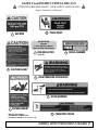
SAFETY RULES
ATTENTION! BECOME ALERT! YOUR SAFETY IS INVOLVED!
Safety is a primary concern in the design and manufacture of our products. Unfortunately, our efforts to provide safe
equipment can be wiped out by an operator’s single careless act.
In addition to the design and conguration of equipment, hazard control and accident prevention are dependent
upon the awareness, concern, judgment, and proper training of personnel involved in the operation, transport,
maintenance and storage of equipment.
It has been said “The best safety device is an informed, careful operator.” We ask you to be that kind of operator.
(Safety Rules continued on next page)
Safety 5
Before putting equipment into service, check and adjust
driveline length. Driveline must not bottom out or pull
apart throughout the full range of the tractor hitch. Do
not operate until driveline length is correct.
Make sure driveline shield safety chain is attached as
shown in this manual. Replace if damaged or broken.
Check that driveline guards rotate freely on driveline
before putting equipment into service.
Before starting power unit, check all equipment
driveline guards for damage. Replace any damaged
guards. Make sure all guards rotate freely on all
drivelines. If guards do not rotate freely on drivelines,
repair and replace bearings before putting equipment
into service.
Remove accumulated debris from this equipment,
power unit, and engine to avoid re hazard.
Power unit must be equipped with cab and seat belt.
Keep seat belt securely fastened. Falling off power unit
can result in death from being run over or crushed.
A minimum 20% of tractor and equipment weight must
be on the tractor front wheels when attachments are in
transport position. Without this weight, tractor could tip
over, causing personal injury or death. The weight may
be attained with a loader, front wheel weights, ballast
in tires or front tractor weights. Weigh the tractor and
equipment. Do not estimate.
• Training
Safety instructions are important! Read all attachment
and power unit manuals; follow all safety rules
and safety decal information. (Replacement manuals and
safety decals are available from your dealer.) Failure
to follow instructions or safety rules can result in
serious injury or death.
If you do not understand any part of this manual and
need assistance, see your dealer.
Know your controls and how to stop engine and
attachment quickly in an emergency.
Operators must be instructed in and be capable of the
safe operation of the equipment, its attachments, and all
controls. Do not allow anyone to operate this equipment
without proper instructions.
Never allow children or untrained persons to operate
equipment.
• Preparation
Check that all hardware is properly installed
and tightened.
Always wear relatively tight and belted clothing to avoid
getting caught in moving parts. Wear sturdy, rough-soled
work shoes and protective equipment for eyes, hair,
hands, hearing, and head; and respirator or lter mask
where appropriate.
Make sure attachment is properly secured, adjusted,
and in good operating condition.
Make sure collar slides freely and is seated rmly in
tractor PTO spline groove.

6 Safety
(Safety Rules continued from previous page)
Make sure all safety decals are installed. Replace if
damaged. (See Safety Decals section for location.)
Make sure shields and guards are properly
installed and in good condition. Replace if damaged.
Inspect and clear area of stones, branches, or other
hard objects that might be thrown, causing injury
or damage.
• Transportation
Power unit must be equipped with cab and seat belt.
Keep seat belt securely fastened. Falling off power unit
can result in death from being run over or crushed.
A minimum 20% of tractor and equipment weight
must be on the tractor front wheels when attachments
are in transport position. Without this weight,
tractor could tip over, causing personal injury or
death. The weight may be attained with a loader,
front wheel weights, ballast in tires or front tractor
weights. Weigh the tractor and equipment. Do not
estimate.
Always comply with all state and local lighting and
marking requirements.
Never allow riders on power unit or attachment.
Do not operate PTO during transport.
Watch for hidden hazards on the terrain.
Do not operate or transport on steep slopes.
Do not operate or transport equipment while under
the inuence of alcohol or drugs.
• Disc Mower Caddy Compatibility
The combined weight of disc mower and caddy should
not exceed 1.5 X weight of the tractor.
Base Disc Mower Caddy weight = 1750 Lbs.
Fully Ballasted Disc Mower weight = 2190 Lbs.
Maximum recommended Disc Mower weight to use with
caddy = 1421 Lbs.
Cab tractor is required when using Frontier Disc Mower
Caddy.
Do not leave cutter bar in up position when parked.
Do not transport fully weighted caddy without a disc
mower installed.
Maximum Compatible Disc Mower Cutting Width =
10’ 2”.
• Operation
Do not allow bystanders in the area when operating,
attaching, removing, assembling, or servicing
equipment.
Never direct discharge toward people, animals, or
property.
Do not operate or transport equipment while under
the inuence of alcohol or drugs.
Keep hands, feet, hair, and clothing away from
equipment while engine is running. Stay clear of all
moving parts.
Operate only in daylight or good articial light.
Always comply with all state and local lighting and
marking requirements.
Never allow riders on power unit or attachment.
Power unit must be equipped with cab and seat
belt. Keep seat belt securely fastened. Falling off
power unit can result in death from being run over or
crushed.
SAFETY RULES
ATTENTION! BECOME ALERT! YOUR SAFETY IS INVOLVED!

Always sit in power unit seat when operating
controls or starting engine. Securely fasten seat
belt, place transmission in neutral, engage brake,
and ensure all other controls are disengaged before
starting power unit engine.
Operate tractor PTO at 540 RPM. Do not exceed.
Do not operate PTO during transport.
Look down and to the rear and make sure area is
clear before operating in reverse.
Do not operate or transport on steep slopes.
Do not stop, start, or change directions suddenly
on slopes.
Use extreme care and reduce ground speed on
slopes and rough terrain.
Watch for hidden hazards on the terrain during opera-
tion. Stop power unit and equipment immediately upon
striking an obstruction. Turn off engine, remove
key, inspect, and repair any damage before
resuming operation.
Leak down or failure of mechanical or hydraulic
system can cause equipment to drop.
• Maintenance
Before dismounting power unit or performing any
service or maintenance, follow these steps: disengage
power to equipment, lower the 3-point hitch and all
raised components to the ground, set parking brake,
stop engine, remove key, and unfasten seat belt.
Before performing any service or maintenance,
disconnect driveline from tractor PTO.
Do not modify or alter or permit anyone else to
modify or alter the equipment or any of its components
in any way.
Always wear relatively tight and belted clothing to
avoid getting caught in moving parts. Wear sturdy,
rough-soled work shoes and protective equipment
for eyes, hair, hands, hearing, and head; and respirator
or lter mask where appropriate.
Make sure attachment is properly secured, adjusted,
and in good operating condition.
Keep all persons away from operator control area
while performing adjustments, service, or
maintenance.
Never go underneath equipment (lowered to the
ground or raised) unless it is properly blocked and
secured. Never place any part of the body under
neath equipment or between moveable parts even
when the engine has been turned off. Hydraulic system
leak down, hydraulic system failures, mechanical
failures, or movement of control levers can cause
equipment to drop or rotate unexpectedly and cause
severe injury or death. Follow Operator’s Manual
instructions for working underneath and blocking
requirements or have work done by a qualied dealer.
Make certain all movement of equipment components has
stopped before approaching for service.
Tighten all bolts, nuts, and screws to torque chart
specications. Check that all cotter pins are installed
securely to ensure equipment is in a safe condition
before putting unit into service.
Make sure all safety decals are installed. Replace if
damaged. (See Safety Decals section for location.)
Make sure shields and guards are properly
installed and in good condition. Replace if damaged.
• Storage
Block equipment securely for storage.
Keep children and bystanders away from storage area.
Follow manual instructions for storage.
Always use a tractor to position equipment for storage.
Never attempt to move equipment by hand.
SAFETY RULES
ATTENTION! BECOME ALERT! YOUR SAFETY IS INVOLVED!
Safety 7

SAFETY and INSTRUCTIONAL DECALS
ATTENTION! BECOME ALERT! YOUR SAFETY IS INVOLVED!
Replace Immediately if Damaged!
8 Safety and Instruction Decals
3
3
4
4
1
8
2
7
6
5
9
5

SAFETY and INSTRUCTIONAL DECALS
ATTENTION! BECOME ALERT! YOUR SAFETY IS INVOLVED!
Replace Immediately if Damaged!
Safety and Instruction Decals 9
RED REFLECTOR
2 Needed
1 Extra Supplied in Manual
Holder for Rear of Disc Mower
5
7
2
1540 RPM
RED REFLECTOR
CAUTION INJURY
9SERIAL NUMBER
3ENTANGLEMENT
6HIGH PRESSURE HYDRAULICS
8TRANSPORT SPEED
HITCH WARNING
TIFC711207
Warning Label Sheet
Part Number 5TIDC611124
(Contains Label #s 1, 2, 3, 4, 6, 7 & 8)
4PINCH POINT

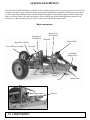
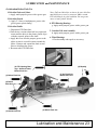
GENERAL DESCRIPTION
Your Frontier DC1000 Disc/Mower Caddy has been carefully designed for easily moving your disc mower. This
manual is provided to give you the necessary operation and maintenance instructions for keeping your caddy in
excellent operating condition. Please read this manual thoroughly. Understand the purpose of the controls and
how to use them. Observe all safety precautions on the machine and as noted throughout this manual. If any
assistance or additional information is needed, contact your authorized Frontier dealer.
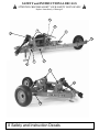
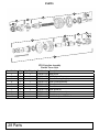
Major components
10 Description
Tire & Wheel Assembly
Manual Tube
Adjustable
Tongue Clevis
Front PTO
Tower
Rear PTO
Tower
Driveline
Hydraulic Cylinder
Lift Arms
Top Link
Jack
A-Frame
Safety Chain
Front Tower
PTO Shield
Rear Tower
PTO Shield

TECHNICAL DESCRIPTION
Model DC1000
Frame
Construction 4” x 6” tubing
Ballasting
Internal Internally weighted and counterbalanced
External Up to 5 tongue and 5 side weights as needed
Hitch
Type Adjustable Clevis Tongue
Operating Dimensions
Overall Length, in. (mm) 140 (3556)
Overall Width, in. (mm) 83 (2108.2)
Overall Height, in. (mm) 44 (1117.6)
Approx. Weight, lb. (kg) without suitcase weights 1750 (795.5)
Approx. Weight, lb. (kg) with suitcase weights 2190 (995.5)
Hydraulic Lift 3-point hitch
Category 2
Cylinder Stroke 6”
Hoses All hydraulic hoses (3) and tips included
Tires
Size 11L x 15SL ribbed implement tires
PTO
Type Equal angle Cat IV 540rpm
(20 spline double locking collar)
Jack
Type Screw Type
Shipping Dimensions
Overall Length, in. (mm) 85.75 (2178.05)
Overall Width, in. (mm) 90 (2286)
Overall Height, in. (mm) 21 (533.4)
Approx. Weight, lb. (kg) without suitcase weights 1975 (897.7)
Description 11

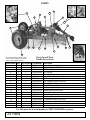
12 Hardware Check Sheet
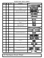
HARDWARE CHECK SHEET
Ref # Qty. Part # Description Picture
1 1 5TIDC611154 44” Double Splined Shaft
2 10 5TIDC611112 PTO HOUSING BOLTS
5/8” x 2” Grade 5 hex bolt with nylon
lock nut
3 1 5TIDC611101 Manual Holder with Hardware (1/46”
x 1” Grade 5 hex bolt with hardware),
Manual and red reector inside
4 1 5TIDC611132 Clevis Tongue
5 1 5TIDC611108 Cat 2 Pin with Lynch Pin
6 8 5TIDC611122 FLANGE BOLTS
5/8” x 2” Grade 5 with nylon lock nut
7 4 5TIDC611113 CROSSBAR BOLTS
3/4” x 2 1/2” Grade 2 with lock washer
and nut
8 8 5TIDC611115 PTO SHIELD BOLTS
1/4” x 1” Grade 5 with at washer, lock
washer and hex nut
9 1 5TIDC611146 Top Link Adjustment Handle (Included
for replacement with Top Link Only)
10 2 5TIDC611109 Cat 1 Pins with Lynch Pins
11 1 5TIDC611136 Safety Chain with 1/2” x 2” Grade 2 with
two washers and nylon lock nut
12 1 5TIDC611103 Hydraulic Cylinder
13 2 5TIDC611102 Eccentric Locking Collars w/ Bearings
14 1 5TIDC611118 Hydraulic Cylinder Safety Stop with
Locking Pin
15 2 5TIDC611120 Hydraulic Hoses with 90° Connecting
Tips
16 1 5TIDC611137 Hydraulic Hose with Straight Connector
17 2 5TIDC611148 &
5TIDC611149
Front & Rear PTO Shields
18 1 5TIDC611114 Hose Clamp with 3/8” x 2” Grade 2 Hex
Bolt and anged nylon lock nut

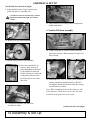
ASSEMBLY & SET UP
• Removing caddy from pallet
Assembly & Set Up 13
1. Place pallet in open area to begin
assembly.
2. Remove box of
hardware and set
aside.
3. Remove tires and wheels from pallet
and set in assembly area.
5. Cut weight retaining strap on end of frame
and rear wheel assembly.
8. Using 15/16” socket, install eight 5/8” x
2” bolts and nylon locknuts into frame and
tighten. (Ref #6)
Note: Ref # refers to the DC1000 Hardware Check
Sheet included at the end of this manual (pg. 12) and in
the hardware box that ships with caddy.
TOOLS REQUIRED: rubber hammer, impact wrench, 1 1/8” socket & wrench, adj. wrench, 3/4” socket
& wrench, regular hammer, 1/2” socket, socket wrench, 15/16” socket, 9/16” socket, allen wrenches, 7/8”
socket, grease gun, and Teon tape or pipe compound.
7. Using forklift, move frame and rear wheel
assembly and line up bolt holes with main
frame. Make sure wheel is to the inside. Use
caution as assembly is extremely heavy.
(continued on next page)
4. Cut weight retaining
strap on end of the
main A-frame.
6. Remove bands from frame and rear wheel
assembly.

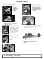
ASSEMBLY & SET UP
14 Assembly & Set Up
CAUTION: A-frame is extremely heavy and has
signicantly unbalanced weight. Use Extreme
Caution!
Note: When installing the bolt in the right rear side,
with assistance, lift the arm to access the hole and
install the head of the bolt on the inside.
9. Using forklift, remove large A-frame from
pallet and place in assembly area.
(continued on next page)
10. Remove all lugs from both hubs.
11. Install wheels and tires on both hubs.
12. Cut zip-ties to remove top link from
A-Frame of caddy
12. Once tires and wheels are
in place, place chocks in
front and behind each wheel.
Using forklift or front end
loader, lift front of caddy and
swing front jack into down
position and lower A-frame
onto jack.
13. Your A-frame is now ready to have components
added to the frame.
• Crossbar Lift Arm Assembly
14. Using two people to lift the crossbar assembly,
place onto A-frame. Make sure that lift arms face
rear of caddy.
(continued from previous page)
15. Install four 3/4” x 2 1/2” Grade 2 bolts with lock
washers and nuts from hardware box (Ref #7)
and tighten. Install all four bolts with nuts facing
toward outside of caddy.

ASSEMBLY & SET UP
Assembly & Set Up 15
• Installing PTO Shaft Shields and
Manual Holder
Note: There
are two PTO
shaft shields
to install.
(Ref #17)
16. Install the smaller PTO guard on the rear
bearing tower and the larger on the front
bearing tower using four (4) 1/4” x 1” hex
bolts, eight (8) 1/4” at washers, four (4) 1/4”
lock washers, and four (4) 1/4” hex nuts from
hardware box. (Ref #8) Use a 7/16” wrench to
secure all nuts and bolts.
17. Install manual holder on front PTO shield
using 1/4” x 1” bolts and nuts. (Ref #3)
Note: Manual Holder contains manual and a red
reector for installation on the rear of disc
mower, IF the mower obscures the view of the
red reector on the back, right-hand side of the
caddy cart. Install this red reector on the back
of the disc mower as close to the right-hand
outermost portion as practical.
• Installing Hydraulic Cylinder Assembly
18. Remove pin clips from hydraulic cylinder
pins and remove pins on both ends of
cylinder. (Ref #12)
19. Install hydraulic cylinder to frame and
crossbar lift assembly.
Note: Be sure that hose hookup ports on
hydraulic cylinder face outside of caddy.
Port
20. Install two hydraulic hoses with elbows to the
hydraulic cylinder. Be sure to use Teon tape
or pipe compound on these ttings. (Ref #15)
Note: The third hydraulic hose with straight
connector in the hardware box is extension
hose that will be used later on the disc mower
cylinder. (Ref #16)
21. Thread hydraulic lines through hole in base of
front bearing mount tower.
(continued on next page)

16 Assembly & Set Up
ASSEMBLY & SET UP
(continued from previous page)
22. Place hydraulic
lines into
hydraulic hose
clamp and
tighten.
23. Using Category 2 pin, install top link
adjustment arm on top of rear bearing
mount tower. (Ref #5)
24. Install top link adjustment
handle (Ref #9) into shaft
body on top link. Line
the handle up directly
over hole in top link. Use
hammer to drive handle
through top link.
26. Install PTO shaft on front bearing
mount tower.
PTO Shaft
25. Using two pins and clevis
tongue, install tongue
assembly on front of
A-frame. (Ref #4 & Ref
#10)
27. Install safety chain on
tongue in bottom hole
of hitch. If tractor hitch
height requires hitch to
be in bottom hole, attach
safety chain to top hole.
(Ref #11)
28. Remove red Hydraulic Cylinder Safety Stop with
Locking Pin and install through hole on rear of
PTO shield. (Ref #14)
29. Your caddy is now ready for your disc
mower.

Attaching 17
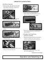
• Attaching Caddy to Tractor
CAUTION: To avoid bodily injury or machine
damage whenever an implement is attached,
put transmission in PARK position and check
the full range of hitch for interference, binding,
or PTO separation. Do not stand between
tractor and implement.
1. Ensure that disc mower caddy is on level
surface with wheels rmly blocked.
2. Back tractor up slowly until hitch is near
caddy tongue.
3. Use caddy jack to adjust caddy tongue to
correct height.
4. Slowly back tractor hitch onto tongue and
align holes. Insert pin into hitch and secure
with R-pin in bottom of hitch pin.
5. Attach safety chain to tractor.
6. Slowly lower jack to let weight of caddy
down onto tractor.
7. Remove jack completely and store on rear of
caddy near rear tire.
8. Attach two hydraulic cylinder hoses on caddy
to rear of tractor.
9. Your caddy is now ready to have a disc
mower attached.
ATTACHING

18 Attaching
ATTACHING
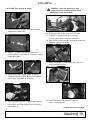
• Attaching Disc Mower to Caddy
1. Ensure that mower is on level surface and
stabilized.
5. Reinstall mounting brackets and bolts,
tighten bolts.
7. Install top link on caddy to top of disc mower.
9. Install PTO shaft from the front of mower to
the rear bearing mount tower.
11. Remove quick coupler
hydraulic nipple from end of
mower disc cylinder line.
Note: Inside measurements of caddy lift arm are
32 3/4”. If necessary, adjust hitch pins on disc
mower to accommodate caddy arm width.
2. Remove mounting brackets from caddy lift
arms.
3. Position caddy arms under mower hitch pins
so that they are just below mower hitch pins.
4. Using hydraulic controls on tractor, slowly
raise the lift arms on caddy to “seat” mower
hitch pins in caddy arms.
6. Install lynch pins in end of each hitch pin.
Note: Top link may have to be adjusted with
adjustment handle in order to t.
8. Once adjusted, tighten lock ring on top link.
10. Install PTO driveline
safety chain to mower.
(continued on next page)

Attaching 19
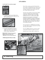
12. Attach teon tape or pipe compound to thread
ttings on hydraulic line. 16. Start tractor and slowly raise caddy lift arms.
(continued from previous page)
13. Attach 9’ hydraulic line extension to end of
mower hydraulic cylinder hose to increase overall
length and tighten.
14. Reattach hydraulic nipple coupler to end of
lengthened hydraulic line. Be sure to use teon
tape or pipe compound on all ttings.
15. Thread extended hydraulic line through opposite
hole in base of PTO housing tower and attach to
rear of tractor.
17. If mower is equipped with it’s own stand,
raise or release stand on mower at this time.
18. Slowly raise cutter bar to full upright position using
hydraulic cylinder on mower.
19. Remove hydraulic cylinder safety stop and place
stop in storage location.
20. Install PTO shaft from front PTO housing
tower to rear of tractor.
(continued on next page)
ATTACHING
WARNING: Cutter bar guard/cover must
be folded back into transport position before
attempting to raise mower blade.

20 Attaching
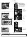
(continued from previous page)
22. If needed, install approved suitcase
weights for ballast on front and rear
weight racks of disc mower caddy to
achieve proper weight balance.
IMPORTANT: Unit must be properly
ballasted before operation. See
“Ballasting” in next section before use.
ATTACHING
21. If equipped, install mower blade release
handle and rope to tractor within easy and
safe reach of operator.
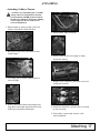
• Ballasting Disc Mower Caddy
Note: Please contact your John Deere Dealer
for assistance with ballasting your caddy cart. If
you are able to ballast your caddy cart without
assistance from your dealer, please follow the
proceeding ballasting procedure:
To ensure safe operation of your mower, ballast
your mower caddy to have positive tongue
weight and a maximum side-to-side weight
distribution ratio of 3.2. Side-to-side weight
distribution ratio should be calculated by
dividing the righthand caddy tire weight by the
lefthand caddy tire weight (RH tire wt./LH tire
wt.) when the mower is fully raised on the cart
and with the cutter bar lowered to the side but
not touching the ground.
Note: All references to RH/LH side of machine
are made with the operator facing the operating
direction of the machine.
Note: The R66949 John Deere suitcase weight
is the approved suitcase weight to use when
ballasting your Frontier Mower Caddy Cart.
Scales under each
tire and jack.
Caddy arms
fully up.
Mower
blade
in down
position
but not
touching
ground.
Page is loading ...
Page is loading ...
Page is loading ...
Page is loading ...
Page is loading ...
Page is loading ...
Page is loading ...
Page is loading ...
Page is loading ...
Page is loading ...
Page is loading ...
Page is loading ...
-
 1
1
-
 2
2
-
 3
3
-
 4
4
-
 5
5
-
 6
6
-
 7
7
-
 8
8
-
 9
9
-
 10
10
-
 11
11
-
 12
12
-
 13
13
-
 14
14
-
 15
15
-
 16
16
-
 17
17
-
 18
18
-
 19
19
-
 20
20
-
 21
21
-
 22
22
-
 23
23
-
 24
24
-
 25
25
-
 26
26
-
 27
27
-
 28
28
-
 29
29
-
 30
30
-
 31
31
-
 32
32


Ask a question and I''ll find the answer in the document
Finding information in a document is now easier with AI
Related papers


Other documents
-
 Cart-Tek GRi-1500Li User manual
-
 Nortrac QH1N Owner's manual
-
Cuisinart CSC-1000 User manual
-
Woods Equipment DS96 User manual
-
Woods BB720X User manual
-
-
Servis-Rhino SR10M User manual
-
-
-
RHINO SE6 User manual

