Page is loading ...

1018039-BPage 1
PILOT PRO MANUAL
Installation and Operating Instructions
NATURAL GAS - W255G, W355G, W505G, W255G-3, W355G-3, W505G-3,
W255G-5, W355G-5, W505G-5, W255G-7, W355G-7, W505G-7
— Donotstoreorusegasolineorotherammable
vapors and liquids in the vicinity of this or any other
appliance.
— WHAT TO DO IF YOU SMELL GAS
•Donottrytolightanyappliance.
•Donottouchanyelectricalswitch;donotuseany
phoneinyourbuilding.
•Immediatelycallyourgassupplierfromaneighbor’s
phone.Followthegassupplier’sinstructions.
•Ifyoucannotreachyourgassupplier,callthere
department.
— Installationandservicemustbeperformedbya
qualiedinstaller,serviceagencyorthegassupplier.
!
WARNING:Iftheinformationintheseinstructionsis
notfollowedexactly,areorexplosionmayresultcausing
propertydamage,personalinjuryorlossoflife.
Cozy Heating Systems, LLC | cozyheaters.com | 855-589-5380 | 3230 Industrial Pkwy | Jeffersonville, IN 47130
WARNING: Operation of any furnace without the properly installed, factory furnished vent system & vent cap could result in
Carbon Monoxide (C.O.) poisoning and possible death. For your safety, this furnace & the vent system should be inspected at least
annually by a qualified service technician.
THE CONTENTS ON THIS MANUAL ARE IN STRICT ACCORDANCE WITH
ANSI STANDARD Z21.71 AND SHOULD BE FOLLOWED BY A PROFESSIONAL INSTALLER ONLY.
INSTALLER:Leavethismanualwiththeappliance.
CONSUMER:Retainthismanualforfuturereference.

1018039-B Page 2
Before Installation
Standards ........................................... 2
Part List ......................................... 3 - 4
Installation
Installation Steps .......................... 5 - 17
Wiring / Electrical ........................ 18 - 25
Starting Pilot Pro ......................... 26 - 28
Lighting Instructions .......................... 29
Troubleshooting ................................. 30
BurnerFlameAdjustment .................. 31
Notes ................................................... 31
Warranty ............................................. 32
CONTENTS READ CAREFULLY BEFORE INSTALLING UNIT
The State of Massachusetts requires that installation
andserviceofagasappliancebeperformedbya
plumberorgastterlicensedintheCommonwealthof
Massachusetts.
These installation instructions are a general guide and do not
supersede applicable local codes and ordinances. Before planning
or making the installation be sure it complies with all phases of the
local heating code. (Or, in the absence of local codes, with the latest
edition of National Fuel Gas Code, ANSI.Z223.1, or CAN1-B149).
The appliance, when installed, must be electrically grounded in
accordance with local codes, or in the absence of local codes, with
the latest edition of National Electrical Code ANSI / NFPA 70, or
Canadian Electrical Code CSA-C22.1.
All of the ANSI and NFPA standards referred to in these installation
instructions are the ones that were applicable at the time the design
of this appliance was created.
Installer must leave these instructions with the consumer, have
them complete, and return the warranty card.
NFPA Standards:
NATIONAL FIRE PROTECTION
ASSOCIATION
1 Batterymarch Park
Quincy, Massachusetts | USA 02169-7471
ANSI & Canadian Standards:
CSA GROUP
178 Rexdale Boulevard,
Toronto, Ontario | Canada M9W 1R3

1018039-BPage 3
PARTS LIST AND REFERENCE
REF PART NO. DESCRIPTION QTY
1 1018002 Battery Pack 1
2 1018000 Control Module 1
3 1018397 Mounting Plate 1
4 1018398 Cover 1
5 50139 Screw, #8 x 3/8" 2
6 1018690 Screw with Knob 2
7 1018526 Screw, #8-32 x 3/4" 5
8 1018331 Screw, #4 x 1.5" 1
9 50052 Nut, #8 7
10 1018330 Nut, #4 1
11 1018036 IID Valve, Natural 1
12 1018001 IID Wiring Harness 1
13 1018037 Outlet Plug 1
14 1018634 Ignitor, Pilot 1
15 1018350 Flame Sensor 1
16 1018302 Wire, Flame Sensor 1
REF PART NO. DESCRIPTION QTY
17 50953 Nut, Wire Gray* 2
18 1018045 Label, Ladder Schematic** 1
19 1018044 Label, Wiring Diagram** 1
20 1018171 Label, Modications** 1
21 1018055 Lighting Instructions* 1
22 1018416 1.5V D-Cell Battery 2
23 1018039 Pilot Pro Manual* 1
24 1018501 Electrical Sleeving* 2
25 B-6395 Tie, Cable 7in* 4
26 1018351 Nut, Flame Sensor 1
27 1018541 Bracket, Valve 1
28 50187 Screw, #10-24 x 3/8" 2
29 84084 Compression Nut, Large 1
30 80037 Compression Nut, Small 1
31 1018543 Pilot Tube 1
* Not shown ** See page 19
Tools Required
forAssembly:
• Phillips - Head
Screwdriver
• Needle Nose Pliers
• 3/16" Drill Bit
• Wire Cutters
Remove this page for faster part reference during assembly.
7
5
7
5
9
9
9
9
9
7
7
4
2
3
1
7
9
9
6
6
13
27
11
29
28
28

1018039-B Page 4
External-ToothLockNut#8 (x7)
50052 . . . . . . . . . . . . . . . . . . . . . . . . . . . . . . . . .
9
External-ToothLockNut#4 (x1)
1018330 .................................
10
PARTS LIST AND REFERENCE
Donotreturnproductifyouaremissingparts.PleaseCall:(855)589-5380
Screw,PhillipsHead,#88-32x3/8" (x2)
50139
. . . . . . . . . . . . . . . . . . . . . . . . . . . . . . . . . . . . .
5
Screw,PhillipsHead,#832x3/4" (x5)
1018526
. . . . . . . . . . . . . . . . . . . . . . . . . . . . . . . .
7
Screw,PhillipsHead,#44-40x1.5" (x1)
1018331
. . . . . . . . . . . . . . . . . . . . .
8
Illustrations in this section are to scale for
faster identification of hardware during assembly:
NOTE: Parts & schematic drawings on current models are shown at: cozyheaters.com | Specications subject to change without notice.
HOW TO PROPERLY ORDER PARTS:
In addition to the part description and numbers, please be prepared to provide: Model number, serial number & type of gas used.
This information can be found on the rating plate that is attached to the heater.
ScrewwithKnob (x2) 1018690
. . . . . .
6
Screw,PhillipsHead,#1024x3/8" (x2)
50187
. . . . . . . . . . . . . . . . . . . . . . . . . . . . . . . . . . . . .
28
30
31
10
8
14
26
15
1216

1018039-BPage 5
Cozy Heating Systems, LLC | cozyheaters.com | 855-589-5380 | 3230 Industrial Pkwy | Jeffersonville, IN 47130
PILOT PRO INSTALLATION
INSTRUCTIONS

1018039-B Page 6
Step 1
SAFETY INSPECTION PROCEDURE PER ANSI Z21.71
EXHIBIT A: Recommended procedure for safety inspection of an existing
appliance installation as a preliminary step to applying an automatic intermittent pilot system.
A. This procedure should be performed prior to any attempt
at modication of the appliance or the installation.
B. If it is determined there is a condition which could
result in unsafe operation, the appliance should be
shut off and the owner advised of the unsafe condition.
The following steps should be followed in making the
safety inspection:
1. Conduct a gas leakage test of the appliance piping
and control system downstream of the shutoff
valve in the supply line to the appliance.
2. Visually inspect the venting system for proper size
and horizontal pitch and determine there is no
blockage or restrictions, leakage or corrosion or
other deciencies which could cause an unsafe
condition.
3. Shut off all gas to the appliance and shut off any
other fuel-burning appliance within the same room.
Use the shutoff valve in the supply line to each
appliance. If a manual gas valve is not in the gas
supply line within 6 feet (1.83 mm) of the appliance
in an accessible location one shall be installed.
4. Inspect burners and crossovers for blockage &
corrosion.
5. Applicable only to warm air heating appliances.
Inspect heat exchangers for cracks, openings or
excessive corrosion.
6. Applicable only to boilers. Inspect for evidence of
water or combustion product leaks.
7. Insofar as is practical, close all building doors and
windows and all doors between the space in which
the appliance is located and other spaces of the
building. Turn on clothes dryers. Turn on any
exhaust fans, such as range hoods and bathroom
exhausts, so they will operate at maximum speed.
Do not operate a summer exhaust fan. Close
replace dampers. If after completing Steps 7
through 12, it is believed sufcient combustion air
is not available, refer to 1.3.4 of the National Fuel
Gas Code (Z223.1) for guidance.
8. Place in operation the appliance being inspected.
Follow the lighting instructions. Adjust thermostat
so appliance will operate continuously.
9. (a) Determine that the pilot is burning properly
and that main burner ignition is satisfactory
by interrupting and reestablishing the
electrical supply to the appliance in any
convenient manner.
(b) Determine manifold pressure in order to match
input after the new control is installed.
10. (a) Visually determine that main burner gas is
burning properly: i.e. , no oating , lifting or
ashback. Adjust the primary air shutter(s)
as required.
(b) If appliance is equipped with high and low ame
control or ame modulation, check for proper
main burner operation at low ame.
11. Test for spillage at the draft hood relief opening
after 5 minutes of main burner operation. Use
a draft gage, the ame of a match or candle, or
smoke from a cigarette, cigar or pipe.
12. Return doors, windows, exhaust fans, replace
dampers and all other fuel-burning appliances to
their previous conditions of use.
13. Applicable only to warm air heating appliances.
Check both limit control and fan control for proper
operation.
Limit control operation can be checked by temporarily
disconnecting the electrical supply to the blower
motor and determining that the limit control acts to
shut off the main burner gas.
Thefollowingprocedureisintendedasaguidetoaidindeterminingthatanapplianceisproperlyinstalled
and is in a safe condition for continuing use.
This procedure is predicated on central furnace and boiler installations equipped with an atmospheric gas burner(s)
and not of the direct vent type. It should be recognized that generalized test procedures cannot anticipate all
situations. Accordingly, in some cases, deviation from this procedure may be necessary to determine safe
operation of the equipment.
INSTALLATION

1018039-BPage 7
INSTALLATION
Step 2
SAFETYINSPECTIONPROCEDUREPERANSIZ21.71;
EXHIBIT B: Procedure for installing automatic intermittent pilot systems.
PRIORTOBEGINNINGTHISPROCEDURE,
apreliminaryexaminationoftheappliance
andtheautomaticintermittentpilotsystem
shouldbemadetodeterminethatthe
automaticintermittentpilotsystemcan
beproperlyappliedtotheappliance.
This procedure is intended as a guide to aid in
safely installing a listed automatic intermittent
pilot system on an existing listed appliance
equipped with an atmospheric gas burner(s) &
not of the direct vent type.
This procedure is based on the assumption
that the history of the specic installation has
been one of safe and satisfactory operation.
This procedure is predicated on central
furnace and boiler installations, and it should be
recognized that generalized procedures cannot
anticipate all situations. Accordingly, in some
cases deviation from this procedure may be
necessary to determine safe operation of the
equipment.
Step 3
• The input rating of the system must be
equal to or greater than the name plate
input rating of the appliance.
• The existing pilot burner shall be used or
if it must be replaced, it shall be replaced
with an identical model located in the same
mounting as the original pilot.
• If electronic components are installed in an
area subject to water then means shall be
provided to protect components.
Thefollowingstepsshouldbefollowed
inmakingthemodications:
1. Performasafetyinspectionoftheexisting
appliance installation.
See Exhibit A (pg 6) for a recommended
procedure for such a safety inspection.
2. Shut off all gas and electricity to the appliance.
To shut off gas use the shutoff valve
in the supply line to the appliance. If
a manual gas valve is not in the gas
supply line within 6 feet (1.83 mm) of the
appliance in an accessible location one
shall be installed. Do not use the shutoff
valve which is provided as part of a
combination control.

1018039-B Page 8
INSTALLATION
Step 5
Allow at
least 10”
from the
housing
to the
wall.
SIDE WALL
HOUSING
Step 4
Remove the heater housing and
lay it on the ground. Also, temporarily
remove and set aside the service
access door.
The Pilot Pro may be installed near the base
of either side of the heater housing. Choose
which side to mount the Pilot Pro.
Be sure to leave enough room to remove the
pilot pro cover for maintenance access.
Foreasyremovalofthecover,
allowatleast10"ofspacefrom
the heater housing.

1018039-BPage 9
A
B
Install on the right
side OR left side of
the housing.
A
B
C
C
3
3
INSTALLATION
Step 6
- Remove the door from the heater housing.
- Locate the Pilot Pro in the carton and remove the cover from
baseplate with a screwdriver.
- Check the inside of the housing for safety labels. Try to avoid
drilling through any pertinent safety information during this step.
3. PLEASE NOTE
C
OF THIS STEP.
Be sure to face the notch / cutout of the mounting plate (3)
toward the wall.
4. Using the mounting plate (3) as a template, align in place as
illustrated. Using a marker or pencil, leave a mark for the three
hole locations on the metal housing.
SET ASIDE THE MOUNTING PLATE
(
3
)
.
5. Drill the three holes into housing using a 3/16” drill bit.
DO NOT DRILL DIRECTLY THROUGH MOUNTING PLATE.
DRILL MAY CRACK THE MOUNTING PLATE.
WALL
WALL
Left
Side of
Heater
WALL
WALL
Right
Side of
Heater
USETHEMOUNTINGPLATE(3)
FOR THE FOLLOWING STEPS.
MOUNTING PLATE MUST BE MOUNTED AS DIRECTED
BELOW OR WIRE HARNESS WILL NOT REACH.
1. PLEASE NOTE
A
OF THIS STEP.
Do not mount the PilotPro any higher than the top of the
access door of the housing.
2. PLEASE NOTE
B
OF THIS STEP.
Align the PilotPro very close to the back edge of the housing.

1018039-B Page 10
INSTALLATION
Step 7
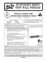
Step 8
With a Phillips head screw driver, attach the controls
assembly to the side of the heater housing using:
- x3 Screws #8 x 3/4” (7)
- x3 Nuts #8 (9)
Temporarily remove the existing Heat Shield
from your heater.
Do not discard. Set aside these parts as
you will be re-installing the Heat Shield later.
9
7
9
9
7
7
DO NOT use a powered drill
for this step, it could crack the
mounting plate.
USE A SCREWDRIVER AND
HAND-TIGHTEN ONLY.

1018039-BPage 11
1. Disconnect all wiring.
2. Disconnect pilot tube from the pilot
assembly. NOTE: Do not lose pilot
orifice. It may want to fall out of
pilot once tube is disconnected.
3. Remove valve from the
burner assembly.
Step 10
IN
PILOT ADJ
INSTALLATION
Verify again that gas to the
appliancehasbeenshutoff.
Disconnect the gas line
from the current valve.
Extract the burner assembly by
removing the two screws holding it in
place (See illustration to the right).
NOTE: Keep screws for re-installation.
Step 9
IN
PILOT ADJ
IN
PILOT ADJ

1018039-B Page 12
Step 11-A
ADJ
PILOT
IN
IN OUT
OUT
11
13
The Pilot Pro valve comes
with two outlets.
1. Prior to installing the valve,
seal the outlet that is on the
same side as pilot tube outlet,
with provided plug (13) and
pipe dope (pipe dope not
included).
NOTE: Ensure that there
are no leaks.
2. Attach the new valve (11)
with pipe dope.
ADJ
P ILO T
IN
ADJ
P ILO T
IN
INSTALLATION
11

1018039-BPage 13
INSTALLATION
Install pilot tubing (31) to the
new valve (11) with compression
nut, large (29).
CAUTION: Tubing
needs to be re-shaped
gently. DO NOT KINK!
Step 12-A
To ensure valve (11) does
not contact the floor, orient valve
from horizontal to a max of 30º.
NOTE:
Temporarily mount the burner in
furnace and ensure valve clears
the floor. If ok, remove burner and
continue to the next step.
Step 11-B
11
pilot
tubing
312911
30º
11
Horizontal : Max 30º :
Maximum

1018039-B Page 14
INSTALLATION
Step 12-B
ADJ
PILOT
IN
PILOT
Install pilot tube (31)
to the pilot assembly using
compression nut, small (30).
Ensure pilot orifice
identified in step 10 is
installed into pilot.
CAUTION:
Tubing needs to be re-shaped
gently. DO NOT KINK!
Step 13
ADJ
PILOT
IN
ADJ
PILOT
IN
PILOT
PILOT
Remove thermopile
from the existing pilot.
30
31
pilot orice

1018039-BPage 15
14
8
14
10
ADJ
PILOT
IN
ADJ
PILOT
IN
Insert flame sensor (15)
into the same location as the
thermopile that was removed on
Step 13. Orient flat tab extending
from the bottom of the flame sensor
(15) parallel to the burner as shown.
Secure in place using the flame
sensor nut (26). Donotover-tighten
asflamesensorcouldcrack!
Connect flame sensor wire (16)
to the blade connector at the base
of the flame sensor (15).
Step 14
26
15
15
16
PILOT
PILOT
INSTALLATION
Step 15
Align the ignitor (14) with the top of
the pilot bracket as illustrated here.
Run the very long and thin #4 screw
(8) through the ignitor (14) and pilot.
Rotate the ignitor (14) as far away
from the burner as possible.
Secure these parts firmly in
place by adding the #4 nut (10).
14
View from above.

1018039-B Page 16
3
/
16
"
14
15
View from
above
INSTALLATION
1
/
8
"
27
11
28
28
Step 17
Add the valve bracket (27) to the base of the
Pilot Pro Valve (11) using:
- x2 Screws #10-24 x 3/8” (28)
Check to ensure the ignitor (14) is located
properly.
- Ignitor probe (14) should be
1/8" under the hood.
- Ignitor probe (14) should be 3/16" away
from flame sensor (15).
- Probe should be bent so that the tip of
the probe sparks only against the hood
of the pilot.
- DO NOT TWIST IGNITOR
WIRE OR IT MAY BREAK
FROM CERAMIC BASE.
DO NOT USE A
BROKEN IGNITOR.
Step 16
15
14

1018039-BPage 17
Step 20
Reinstall the Heat Shield that was removed from
your heater during this installation.
INSTALLATION
ADJ
PILO T
IN
Reinstall the burner assembly using the original two
screws that held it in place (See illustration to the right).
Next, re-connect the gas line to the valve.
Step 18
If necessary,
using pliers, bend the
corner of the heat shield
away from the flame
sensor (15) and wire
connector (16).
Donotbend
morethan1/2"from
thecornerasshown.
Step 19
Ensure flame sensor (15) and flame sensor wire
connector (16) Do NOT contact any metal surface
such as the heat shield and pilot tube.
16
15
16
15
heat
shield
pilot
tube
1
/
2
"

1018039-B Page 18
Cozy Heating Systems, LLC | cozyheaters.com | 855-589-5380 | 3230 Industrial Pkwy | Jeffersonville, IN 47130
WARNING: PLEASE USE
CAUTION WHILE INSTALLING THE
ELECTRICAL CONNECTION
PILOT PRO ELECTRICAL
CONNECTION

1018039-BPage 19
ELECTRICAL CONNECTIONPILOT PRO ELECTRICAL CONNECTION
WARNING: PLEASE USE CAUTION WHILE INSTALLING THE ELECTRICAL CONNECTION
18
20
19
Step 1
2. Apply the ladder schematic (18),
wiring diagram (19) and the
modification sticker (20) inside
the front panel of the heater.
NOTE: Place the labels near the base
(on either side). They should be visible
through the service door.
18
1. Fill out and apply modification
sticker (20) with date, name and
contact information.
WARNING:
DO NOT ATTEMPT TO LIGHT THIS APPLIANCE MANUALLY.
BURN, INJURY OR ELECTRIC SHOCK MAY RESULT.
This appliance has been modified to use an automatic intermittent
pilot system. Attempting to light this appliance manually may cause
burns, injury or electric shock.
Date of Installation: ____________________________________
Name of Installer:
______________________________________
Contact for Installer (Address or Telephone):
________________
______________________________________________________
______________________________________________________
1018171-A
20
19

1018039-B Page 20
PILOT PRO ELECTRICAL CONNECTION
WARNING: PLEASE USE CAUTION WHILE INSTALLING THE ELECTRICAL CONNECTION
Step 2
Reattach the front panel housing on the heater.
NOTE: Leave the access door open until installation has
been complete.
Makesuretherearenosharp
edgesontherimoftheheater
housing that could potentially
damagethewires.
Step 3
2
3
Direct the control module
wires (2) through the small
notch on the side of the
mounting plate (3).
Tuck the wires around
the edge of the heater
housing, against the
wall, and inside
the heater.
On the inside of the heater, you will see orange
and black wires extending from the burner.
Lead the orange pilot ignitor wire (14) and black
flame sensor wire (16) out of the heater beside
the wires you have just directed in.
3
16
16
14
14
2
3
25
Run a cable tie (25) through the
small hole beside the notch on the
mounting plate (3).
Gather and secure the wires to
and from the Control Module (2)
with the cable tie (25).
/