Page is loading ...

2014 Microchip Technology Inc. DS50002240A
MCP39F501
Power Monitor
Demonstration Board
User’s Guide

DS50002240A-page 2 2014 Microchip Technology Inc.
Information contained in this publication regarding device
applications and the like is provided only for your convenience
and may be superseded by updates. It is your responsibility to
ensure that your application meets with your specifications.
MICROCHIP MAKES NO REPRESENTATIONS OR
WARRANTIES OF ANY KIND WHETHER EXPRESS OR
IMPLIED, WRITTEN OR ORAL, STATUTORY OR
OTHERWISE, RELATED TO THE INFORMATION,
INCLUDING BUT NOT LIMITED TO ITS CONDITION,
QUALITY, PERFORMANCE, MERCHANTABILITY OR
FITNESS FOR PURPOSE. Microchip disclaims all liability
arising from this information and its use. Use of Microchip
devices in life support and/or safety applications is entirely at
the buyer’s risk, and the buyer agrees to defend, indemnify and
hold harmless Microchip from any and all damages, claims,
suits, or expenses resulting from such use. No licenses are
conveyed, implicitly or otherwise, under any Microchip
intellectual property rights.
Note the following details of the code protection feature on Microchip devices:
• Microchip products meet the specification contained in their particular Microchip Data Sheet.
• Microchip believes that its family of products is one of the most secure families of its kind on the market today, when used in the
intended manner and under normal conditions.
• There are dishonest and possibly illegal methods used to breach the code protection feature. All of these methods, to our
knowledge, require using the Microchip products in a manner outside the operating specifications contained in Microchip’s Data
Sheets. Most likely, the person doing so is engaged in theft of intellectual property.
• Microchip is willing to work with the customer who is concerned about the integrity of their code.
• Neither Microchip nor any other semiconductor manufacturer can guarantee the security of their code. Code protection does not
mean that we are guaranteeing the product as “unbreakable.”
Code protection is constantly evolving. We at Microchip are committed to continuously improving the code protection features of our
products. Attempts to break Microchip’s code protection feature may be a violation of the Digital Millennium Copyright Act. If such acts
allow unauthorized access to your software or other copyrighted work, you may have a right to sue for relief under that Act.
Microchip received ISO/TS-16949:2009 certification for its worldwide
headquarters, design and wafer fabrication facilities in Chandler and
Tempe, Arizona; Gresham, Oregon and design centers in California
and India. The Company’s quality system processes and procedures
are for its PIC
®
MCUs and dsPIC
®
DSCs, KEELOQ
®
code hopping
devices, Serial EEPROMs, microperipherals, nonvolatile memory and
analog products. In addition, Microchip’s quality system for the design
and manufacture of development systems is ISO 9001:2000 certified.
QUALITY MANAGEMENT S
YSTEM
CERTIFIED BY DNV
== ISO/TS 16949 ==
Trademarks
The Microchip name and logo, the Microchip logo, dsPIC,
FlashFlex, K
EELOQ, KEELOQ logo, MPLAB, PIC, PICmicro,
PICSTART, PIC
32
logo, rfPIC, SST, SST Logo, SuperFlash
and UNI/O are registered trademarks of Microchip Technology
Incorporated in the U.S.A. and other countries.
FilterLab, Hampshire, HI-TECH C, Linear Active Thermistor,
MTP, SEEVAL and The Embedded Control Solutions
Company are registered trademarks of Microchip Technology
Incorporated in the U.S.A.
Silicon Storage Technology is a registered trademark of
Microchip Technology Inc. in other countries.
Analog-for-the-Digital Age, Application Maestro, BodyCom,
chipKIT, chipKIT logo, CodeGuard, dsPICDEM,
dsPICDEM.net, dsPICworks, dsSPEAK, ECAN,
ECONOMONITOR, FanSense, HI-TIDE, In-Circuit Serial
Programming, ICSP, Mindi, MiWi, MPASM, MPF, MPLAB
Certified logo, MPLIB, MPLINK, mTouch, Omniscient Code
Generation, PICC, PICC-18, PICDEM, PICDEM.net, PICkit,
PICtail, REAL ICE, rfLAB, Select Mode, SQI, Serial Quad I/O,
Total Endurance, TSHARC, UniWinDriver, WiperLock, ZENA
and Z-Scale are trademarks of Microchip Technology
Incorporated in the U.S.A. and other countries.
SQTP is a service mark of Microchip Technology Incorporated
in the U.S.A.
GestIC and ULPP are registered trademarks of Microchip
Technology Germany II GmbH & Co. KG, a subsidiary of
Microchip Technology Inc., in other countries.
All other trademarks mentioned herein are property of their
respective companies.
© 2014, Microchip Technology Incorporated, Printed in the
U.S.A., All Rights Reserved.
Printed on recycled paper.
ISBN: 978-1-62077-874-6

2014 Microchip Technology Inc. DS50002240A-page 3
Object of Declaration: MCP39F501 Power Monitor Demonstration Board User’s Guide

MCP39F501 Power Monitor Demonstration Board User’s Guide
DS50002240A-page 4 2014 Microchip Technology Inc.
NOTES:

MCP39F501 POWER MONITOR
DEMONSTRATION BOARD
USER’S GUIDE
2014 Microchip Technology Inc. DS50002240A-page 5
Table of Contents
Preface ...........................................................................................................................7
Introduction............................................................................................................ 7
Document Layout.................................................................................................. 7
Conventions Used in this Guide............................................................................ 8
Recommended Reading........................................................................................9
The Microchip Web Site........................................................................................ 9
Customer Support.................................................................................................9
Document Revision History................................................................................... 9
Chapter 1. Product Overview
1.1 Introduction ...................................................................................................11
1.2 What the MCP39F501 Power Monitor Demonstration Board Kit Includes ...12
Chapter 2. Installation and Operation
2.1 Getting Started .............................................................................................13
Chapter 3. Hardware Description
3.1 Input and Analog Front End .........................................................................17
3.2 Power Supply Circuit .................................................................................... 18
Appendix A. Schematic and Layouts
A.1 Introduction ..................................................................................................19
A.2 Schematics and PCB Layout .......................................................................19
A.3 Board – Schematic ....................................................................................... 20
A.4 Board – Top Silk ..........................................................................................21
A.5 Board – Top Copper and Silk .......................................................................22
A.6 Board – Top Copper ....................................................................................23
A.7 Board – Bottom Copper ...............................................................................24
A.8 Board – Bottom Copper and Silk .................................................................25
A.9 Board – Bottom Silk .....................................................................................26
Appendix B. Bill of Materials (BOM)
Worldwide Sales and Service ....................................................................................30

MCP39F501 Power Monitor Demonstration Board User’s Guide
DS50002240A-page 6 2014 Microchip Technology Inc.
NOTES:

MCP39F501 POWER MONITOR
DEMONSTRATION BOARD
USER’S GUIDE
2014 Microchip Technology Inc. DS5002240A-page 7
Preface
INTRODUCTION
This chapter contains general information that will be useful to know before using the
MCP39F501 Power Monitor Demonstration Board. Items discussed in this chapter
include:
• Document Layout
• Conventions Used in this Guide
• Recommended Reading
• The Microchip Web Site
• Customer Support
• Document Revision History
DOCUMENT LAYOUT
This document describes how to use the MCP39F501 Power Monitor Demonstration
Board as a demonstration board to evaluate the MCP39F501 device. The manual
layout is as follows:
• Chapter 1. “Product Overview” – Provides important information about the
MCP39F501 Power Monitor Demonstration Board
• Chapter 2. “Installation and Operation” – Provides information on using the
MCP39F501 Power Monitor Demonstration Board, including Section 2.1.3 “Step
3: Connect the USB cable to a PC with the installed “MCP39F501 Power
Monitor Utility” software” that describes wiring the line and load connections
• Chapter 3. “Hardware Description” – Provides details on the function blocks of
the power monitor, including the analog front-end design and power supply design
• Appendix A. “Schematic and Layouts” – Shows the schematic and layout
diagrams
• Appendix B. “Bill of Materials (BOM)” – Lists the parts used to build the
MCP39F501 Power Monitor Demonstration Board
NOTICE TO CUSTOMERS
All documentation becomes dated, and this manual is no exception. Microchip tools and
documentation are constantly evolving to meet customer needs, so some actual dialogs
and/or tool descriptions may differ from those in this document. Please refer to our web site
(www.microchip.com) to obtain the latest documentation available.
Documents are identified with a “DS” number. This number is located on the bottom of each
page, in front of the page number. The numbering convention for the DS number is
“DSXXXXXA”, where “XXXXX” is the document number and “A” is the revision level of the
document.
For the most up-to-date information on development tools, see the MPLAB
®
IDE online help.
Select the Help menu, and then Topics to open a list of available online help files.

MCP39F501 Power Monitor Demonstration Board User’s Guide
DS5002240A-page 8 2014 Microchip Technology Inc.
CONVENTIONS USED IN THIS GUIDE
This manual uses the following documentation conventions:
DOCUMENTATION CONVENTIONS
Description Represents Examples
Arial font:
Italic characters Referenced books MPLAB
®
IDE User’s Guide
Emphasized text ...is the only compiler...
Initial caps A window the Output window
A dialog the Settings dialog
A menu selection select Enable Programmer
Quotes A field name in a window or
dialog
“Save project before build”
Underlined, italic text with
right angle bracket
A menu path File>Save
Bold characters A dialog button Click OK
A tab Click the Power tab
N‘Rnnnn A number in verilog format,
where N is the total number of
digits, R is the radix and n is a
digit.
4‘b0010, 2‘hF1
Text in angle brackets < > A key on the keyboard Press <Enter>, <F1>
Courier New font:
Plain Courier New Sample source code #define START
Filenames autoexec.bat
File paths c:\mcc18\h
Keywords _asm, _endasm, static
Command-line options -Opa+, -Opa-
Bit values 0, 1
Constants 0xFF, ‘A’
Italic Courier New A variable argument file.o, where file can be
any valid filename
Square brackets [ ] Optional arguments mcc18 [options] file
[options]
Curly brackets and pipe
character: { | }
Choice of mutually exclusive
arguments; an OR selection
errorlevel {0|1}
Ellipses... Replaces repeated text var_name [,
var_name...]
Represents code supplied by
user
void main (void)
{ ...
}

Preface
2014 Microchip Technology Inc. DS5002240A-page 9
RECOMMENDED READING
This user's guide describes how to use MCP39F501 Power Monitor Demonstration
Board. Another useful documents is listed below. The following Microchip document is
available and recommended as a supplemental reference resource.
MCP39F501 Data Sheet – “Single Phase Energy and Power Monitoring IC with
Calculation” (DS20005256)
This data sheet provides detailed information regarding the MCP39F501 device.
THE MICROCHIP WEB SITE
Microchip provides online support via our web site at www.microchip.com. This web
site is used as a means to make files and information easily available to customers.
Accessible by using your favorite Internet browser, the web site contains the following
information:
• Product Support – Data sheets and errata, application notes and sample
programs, design resources, user’s guides and hardware support documents,
latest software releases and archived software
• General Technical Support – Frequently Asked Questions (FAQs), technical
support requests, online discussion groups, Microchip consultant program
member listing
• Business of Microchip – Product selector and ordering guides, latest Microchip
press releases, listing of seminars and events, listings of Microchip sales offices,
distributors and factory representatives
CUSTOMER SUPPORT
Users of Microchip products can receive assistance through several channels:
• Distributor or Representative
• Local Sales Office
• Field Application Engineer (FAE)
• Technical Support
Customers should contact their distributor, representative or field application engineer
(FAE) for support. Local sales offices are also available to help customers. A listing of
sales offices and locations is included in the back of this document.
Technical support is available through the web site at: http://support.microchip.com.
DOCUMENT REVISION HISTORY
Revision A (February 2014)
• Initial Release of this Document.

MCP39F501 Power Monitor Demonstration Board User’s Guide
DS5002240A-page 10 2014 Microchip Technology Inc.
NOTES:

MCP39F501 POWER MONITOR
DEMONSTRATION BOARD
USER’S GUIDE
2014 Microchip Technology Inc. DS50002240A-page 11
Chapter 1. Product Overview
1.1 INTRODUCTION
The MCP39F501 Power Monitor Demonstration Board is a fully functional single-phase
power monitor. This low-cost design does not use any transformers and requires few
external components. The system calculates active power, reactive power, RMS
current, RMS voltage and other typical power quantities, as defined in the MCP39F501
data sheet.
The Microchip Energy Meter 1-Phase software is used to calibrate and monitor the
system, and can be used to create custom calibration setups. For some accuracy
requirements, only a single-point calibration may be needed. The energy meter
software offers an automated step-by-step calibration process that can be used to
quickly calibrate energy meters.
This demonstration board uses the MCP39F501 Power Monitor Utility software for
evaluation via a USB connection to the board. A download link for this software can be
found on the evaluation board’s web page. For instructions on the use of this software,
refer to the software’s supporting documentation included within the application install
package.
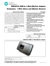
FIGURE 1-1: MCP39F501 Power Monitor Demonstration Board.

MCP39F501 Power Monitor Demonstration Board User’s Guide
DS50002240A-page 12 2014 Microchip Technology Inc.
1.2 WHAT THE MCP39F501 POWER MONITOR DEMONSTRATION BOARD KIT
INCLUDES
This MCP39F501 Power Monitor Demonstration Board kit includes:
• MCP39F501 Power Monitor Demonstration Board (ARD00455)
• Important Information Sheet
• Mini USB cable
• AC Line cable
• AC Load cable
• Plastic enclosure

MCP39F501 POWER MONITOR
DEMONSTRATION BOARD
USER’S GUIDE
2014 Microchip Technology Inc. DS50002240A-page 13
Chapter 2. Installation and Operation
2.1 GETTING STARTED
To use the MCP39F501 Power Monitor Demonstration Board, follow the steps
described in the sections below. The meter design uses a 5A load for calibration current
and a maximum current (I
MAX
) of 15A.
It is not recommended to put more than 15A through the AC plugs mounted on the
Printed Circuit Board (PCB).
To test the calibrated meter, the following connections can be made:
2.1.1 Step 1: Wiring connections
Figure 2-1 identifies the line and load connections of the MCP39F501 Power Monitor
Demonstration Board.
FIGURE 2-1: Connecting the MCP39F501 Power Monitor Demonstration
Board.
2.1.2 Step 2: Turn on line/load power to the meter (power the meter)
The meter will turn on when the line connection has between 90V to 220V connected.
2.1.3 Step 3: Connect the USB cable to a PC with the installed
“MCP39F501 Power Monitor Utility” software
Select the appropriate COM port. If the meter is connected correctly, the connection
status in the bottom left corner of the software will display “Meter Connected”. If no
meter is found, the status will be “Meter Disconnected”. Check that the correct COM
port was selected and try again.

MCP39F501 Power Monitor Demonstration Board User’s Guide
DS50002240A-page 14 2014 Microchip Technology Inc.
NOTES:

MCP39F501 POWER MONITOR
DEMONSTRATION BOARD
USER’S GUIDE
2014 Microchip Technology Inc. DS50002240A-page 15
Chapter 3. Hardware Description
FIGURE 3-1: MCP39F501 Power Monitor Demonstration Board Top View – Hardware Components.
Legend:
1 = MCP39F501 5 = Output LEDs for digital I/O
2 = +9V DC Input (non-isolated) 6 = Headers for pulse testing (isolated)
3 = Connections to external shunt current
sensing resistor
7 = USB Connection (isolated)
4 = Configuration jumpers
1
7
6
5
4
3
2

MCP39F501 Power Monitor Demonstration Board User’s Guide
DS50002240A-page 16 2014 Microchip Technology Inc.
FIGURE 3-2: MCP39F501 Power Monitor Demonstration Board Bottom View – Hardware
Components.
Legend:
8 = Opto-isolators
9=Power supply
10 = Current sensing shunt (2 m)
11 = Isolation IC
12 = MCP2200 for USB connection
12
8
11
10
9

Hardware Description
2014 Microchip Technology Inc. DS50002240A-page 17
3.1 INPUT AND ANALOG FRONT END
The MCP39F501 Power Monitor Demonstration Board comes populated with
components designed for 220V line voltage. However, it will work from 90V to 230V. At
the bottom of the main board, there are the high-voltage line and neutral connections.
There are four connections from the PCB to the meter casing. They are labeled LINE,
NEUTRAL, SHUNT1 and SHUNT2. The shunt sits on the high- or line-side of a
two-wire system and the meter employs a hot or “live” ground. The wires going into the
shunt to SHUNT1 and SHUNT2 should be twisted together. The wires going into the
LINE and NEUTRAL side of the meter should be twisted together, and also kept away
from the SHUNT1 and SHUNT2 wires, if possible.
The neutral side of the two-wire system goes into a resistor divider on the voltage
channel input. Anti-aliasing low-pass filters are included. The voltage channel uses two
499 k resistors to achieve a divider ratio of 1000:1. For a line voltage of 230 V
RMS
,
the channel 1 input signal size will be 230 mV
RMS
.
FIGURE 3-3: Analog Front-End Circuitry.
Note that all of the analog circuitry associated with this part of the circuit is connected
to the analog ground plane (A
GND
).
499 k
LINE
499 k
1k
100 nF
A
GND
A
GND
V1+
1k
NEUTRAL
33 nF
A
GND
I1+
1k
NEUTRAL OUT
33 nF
A
GND
I1-
2m
Shunt
MCP39F501

MCP39F501 Power Monitor Demonstration Board User’s Guide
DS50002240A-page 18 2014 Microchip Technology Inc.
3.2 POWER SUPPLY CIRCUIT
The power supply circuit for the MCP39F501 Power Monitor Demonstration Board
uses a half-wave rectified signal and a +3.3V voltage regulator.
FIGURE 3-4: Low-Cost Power Supply Circuit.
150 FB
33
1.5 µF
470 µF
1
3
2
N
L
0.1 µF
+3.3 VD
+
10 µF
IN OUT
GND
MCP1754
0.1 µF
A
GND
GNDB GNDB
GNDB
GNDB
GNDB
GNDB
GNDB
NT
‘
0.1 µF
10 µF
A
GND
A
GND
+3.3 VA
100
+9V DC Power In
(DO NOT USE WHILE
METER IS CONNECTED
TO MAINS!)

MCP39F501 POWER MONITOR
DEMONSTRATION BOARD
USER’S GUIDE
2014 Microchip Technology Inc. DS50002240A-page 19
Appendix A. Schematic and Layouts
A.1 INTRODUCTION
This appendix contains the following schematics and layouts for of the MCP39F501
Power Monitor Demonstration Board:
• Board – Schematic
• Board – Top Silk
• Board – Top Copper and Silk
• Board – Top Copper
• Board – Bottom Copper
• Board – Bottom Copper and Silk
• Board – Bottom Silk
A.2 SCHEMATICS AND PCB LAYOUT
The layer order is shown in Figure A-1.
FIGURE A-1: Layer Order.
Top Layer
Bottom Layer

MCP39F501 Power Monitor Demonstration Board User’s Guide
DS50002240A-page 20 2014 Microchip Technology Inc.
A.3 BOARD – SCHEMATIC
+9V IN POWER
AGND
AGND
Line shunt
AGND
AGND
Voltage channel
Current Channel
Ferrite Bead 0805
L1
Ferrite Bead 0805
L2
MRA4005
D1
MRA4005
D2
AGND
VOLTAGE IN
3.3A3.3D
Power Jack 2.5mm
2
3
1
J1
NDP
C18
10uF
1206
C16
GNDB
15V
D3
LINE
NEUTRAL
VOLTAGE IN
GNDB
+9V IN
Ferrite Bead Radial
L4
Via_2.5x1.5
CP1
Via_2.5x1.5
CP2
470uF
AL-F
C20
GNDB
GNDB GNDB
GNDB
GNDB
Ferrite Bead Radial
L3
0.01uF
RAD_10x13x4
C19
0.1uF
0603
C15
0.1uF
0603
C17
TP3
1%
2.49
0603
DNP
R10
1k
1%
0603
R20
0.1uF
0603
C23
10uF
1206
C22
AGND AGND
100 5%
0603
R27
LINE
NEUTRAL N_OUT
N_OUT
0.1uF
0603
C7
NEUTRAL
G
2
N
3
L
1
IEC Inlet
J6
G
2
N
3
L
1
IEC Outlet
J7
[SHUNT]
S10K420
MOV1
12
Shunt 2mOhm
R6
VOUT
3
VIN
1
GND
2
MCP1754-3.3V
U2
MPU_TX1
MPU_RX1
GNDB
3.3D
0.1uF
0603
C9
0.1uF
0603
C4
AGND
3.3A
AGND
MPU_PGC
MPU_PGD
TP1
DIO0
HDR M 1x2 VERT
1
2
J4
GNDB GNDB
5%
1k
0603
R50
LED 5mm Red
12
LD2
PC365N
2 3
1
4
U8
3.3k
5%
0603
R51
5%
4.7k
0603
R1
3.3A
AGND
3.3A
0.1uF
0603
C11
AGND
3.3D
0.1uF
0603
C3
AGND
3.3A
DIO1
HDR M 1x2 VERT
1
2
J5
GNDB
GNDB
5%
1k
0603
R11
LED 5mm Red
12
LD3
PC365N
2 3
1
4
U1
3.3k
5%
0603
R12
GND_ISO
MPU_RX1
MPU_TX1
3.3D
3.3D
GNDB
GNDB
GND_ISO
GND_ISO
1uF
0603
C27
5VUSB
5VUSB
5VUSB
5VUSB
GND_ISO
GND_ISO
GND_ISO
Isolation
Barrier
USB_D-
USB_D+
12MHz
2
31
X1
5VUSB
5VUSB
5%
390
0603
R39
5%
390
0603
R38
5%
390
0603
R37
1uF
0603
C25
0.1uF
0603
C24
greenred
LED RD/GN SMD
2 1
43
GREEN
RED
LD1
IL721-3E
VDD1
1
OUT1
2
IN2
3
GND1
4
VDD2
8
IN1
7
OUT2
6
GND2
5
U5
MCP2200
VDD
1
OSC1
2
OSC2
3
RST
4
GP7/TxLED
5
GP6/RxLED
6
GP5
7
GP4
8
GP3
9
TX
10
RTS
11
RX
12
CTS
13
GP2
14
GP1
15
GP0
16
VUSB
17
D-
18
D+
19
VSS
20
U4
0.1uF
0603
C26
MCP2200_RX
MCP2200_TX
GND_ISO
USB_D-
USB_D+
GND_ISO
5VUSB
USB-B-Mini TH
ID
4
VBUS
1
GND
5
D-
2
D+
3
J2
DR
28
NC
2
NC
3
TEST_B
13
OSCI
6
OSCO
7
AN_IN/DIO2
20
NC
8
NC
9
MODE/DIR
1
RESET
10
AVDD
11
DIO3
22
A0/DIO0
14
A1/DIO1
15
CH0+
16
CH0-
17
CH1-
18
CH1+
19
AGND
21
UART_TX
12
UART_RX
4
REFIN+/OUT
23
DGND
24
DVDD
25
DGND
27
MCLR
26
TEST_A
5
EP
29
U6
12
HDR M 1x2 VERT
J10
4.7k
5%
0603
R18
18pF
0603
C1
18pF
0603
C5
123
J11
123
J13
3.3D
1k
5%
0603
R19
HIGH LOW
A1
A0
HIGH LOW
12
HDR M 1x2 VERT
J12
AN_DIO2
DIO3
GNDB
GNDB
GNDB
GNDB
GNDB
DIO2
HDR M 1x2 VERT
1
2
J14
GNDB GNDB
5%
1k
0603
R21
LED 5mm Red
12
LD5
PC365N
2 3
1 4
U7
3.3k
5%
0603
R22
DIO3
HDR M 1x2 VERT
1
2
J15
GNDB GNDB
5%
1k
0603
R23
LED 5mm Red
12
LD6
PC365N
2 3
1
4
U9
3.3k
5%
0603
R24
DIO2
DIO3
TEMP_IN
3.3D
VDD
1
VSS
3
VOUT
2
MCP9700
U10
123
J16
AN_DIO2
DIO2
ANALOG IN DIO2
DIO1
DIO0
MODE/DIR
HDR M 1x2 VERT
1
2
J9
GNDB GNDB
5%
1k
0603
R3
LED 5mm Red
12
LD4
PC365N
2 3
1
4
U3
3.3k
5%
0603
R13
MODE_DIR
123
J8
MODE_DIR
3.3D
DIO0
DIO1
SINGLE MULT.
SINGLE
SINGLE
GNDB
GNDB
499k
2010
1%
R8
499k
2010
1%
R7
1k
0603
1%
R14
1k
0603
1%
R4
1k
0603
1%
R2
33nF
50V
0603
C2
33nF
50V
0603
C6
33nF
50V
0603
C10
123
J17
270R
0603
R9
120R
0603
R5
12
J18
ISO_TX
ISO_RX
ISO_TX
ISO_RX
Ferrite Bead 0805
L5
1.5UF 250VAC
C21
4MHz
631-1033-1-ND
Y1
33 Ohms
45F33RE-ND
R34
3.3D
/