Compaq DL360 - ProLiant - Photon User manual
- Type
- User manual

HP Flex-10 and SR-IOV—What is the difference? ....................................................................................... 1
Three-phase power distribution in c7000 enclosures ................................................................................. 3
PUE and DCE—Useful metrics for overall data center efficiency .................................................................. 6
Meet the Expert—Wayne Vuong ................................................................................................................ 7
Recently published industry standard server technology papers ............................................................... 8
Contact us .................................................................................................................................................. 8
HP Flex-10 and SR-IOV—What is the difference?
Improving I/O performance
As virtual machine software enables higher efficiencies in CPU use, these same efficiency enablers place more overhead on
physical assets. HP Flex-10 Technology and Single Root I/O Virtualization (SR-IOV) both share the goal of improving I/O
efficiency without increasing the overhead burden on CPUs and network hardware. Flex-10 and SR-IOV technologies
accomplish this goal through different approaches. This article explores the differences in architecture and implementation
between Flex-10 and SR-IOV.
How these two technologies differ and why it matters
HP Flex-10 Technology
Flex-10 technology is a hardware-based solution that enables users to partition a 10 gigabit Ethernet (10GbE) connection and
regulate the bandwidth of each partition. HP Flex-10 is available only with Virtual Connect (VC), and is currently available for
implementation only with supported HP BladeSystem servers.
Flex-10 can be deployed now with HP BladeSystem servers, and with relatively little modification to existing I/O architecture.
Adding Flex-10-capable network devices and virtual connect modules to existing HP BladeSystem infrastructure allows
administrators to take advantage of the considerable I/O control and refinement delivered by Flex-10 technology.
Using Flex-10 technology, administrators can configure a single BladeSystem 10Gb network port to represent four physical
network interface controllers (NICs), also called FlexNICs, with a total bandwidth of 10Gbps. These four FlexNICs appear to
the operating system (OS) as discrete NICs, each with its own driver. While the FlexNICs share the same physical port, traffic
flow for each one is isolated with its own MAC address and virtual local area network (VLAN) tags between the FlexNIC and
ISS Technology Update
Volume 8, Number 3
Keeping you informed of the latest ISS technology

ISS Technology Update Volume 8, Number 3
2
VC Flex-10 interconnect module. Using the VC interface, an administrator can set and control the transmit bandwidth available
to each FlexNIC.
Each dual-port Flex-10 device supports up to eight FlexNICs, four on each physical port, and each Flex-10 Interconnect Module
can support up to 64 FlexNICs.
Single Root I/O Virtualization (SR-IOV)
SR-IOV’s ability to scale is a major advantage. The initial Flex-10 offering is based on the original PCIe definition that is limited
to 8 PCI functions per given device (4 FlexNics per 10Gb port on a dual port device). With SR-IOV, there is a function called
Alternative Route Identifiers (ARI) that allows expansion of up to 256 PCIe functions. The scalability inherent in the SR-IOV
architecture has the potential to increase server consolidation and performance.
Another SR-IOV advantage is the prospect of performance gains achieved by removing the hypervisor from the main data path.
Hypervisors are essentially another operating system providing CPU, memory, and I/O virtualization capabilities to accomplish
resource management and data processing functions. The data processing functionality places the hypervisor squarely in the
main data path.
In current I/O architecture, data communicated to and from a guest OS is routinely processed by the hypervisor. Both outgoing
and incoming data is transformed into a format that can be understood by a physical device driver. The data destination is
determined, and the appropriate send or receive buffers are posted. All of this processing requires a great deal of data
copying, and the entire process creates serious performance overhead.
With SR-IOV, the hypervisor is no longer required to process, route, and buffer both outgoing and incoming packets. Instead,
the SR-IOV architecture has exposed the underlying hardware to the guest OS, and while the guest OS still employs virtual
Ethernet, it is now ”paravirtualized.” Paravirtualization lets the guest OS translate data by employing a virtual machine monitor
(VMM). Calls to the hardware device drivers from the guest OS are replaced with calls to the VMM which handles the data
processing tasks formerly performed by the hypervisor. This removes the hypervisor from the main data path and eliminates a
great deal of performance overhead. The hypervisor continues to allocate resources and handle exception conditions, but it is
no longer required to perform routine data processing.
Since SR-IOV is a hardware I/O implementation, it also uses hardware-based security and quality of service (QoS) features
incorporated into the physical host server.
Summary
Advantages associated with using Flex-10 technology are significant. The ability to adjust transmit bandwidth by partitioning
data flow makes 10GbE more cost effective and easier to manage. It is easier to aggregate multiple 1Gb data flows and fully
utilize 10Gb bandwidth. The fact that Flex-10 is hardware based means that multiple FlexNICs are added without the
additional processor overhead or latency associated with server virtualization (virtual machines). Significant infrastructure
savings are also realized since additional server NIC mezzanine cards and associated interconnect modules may not be
needed.
See http://h20000.www2.hp.com/bc/docs/support/SupportManual/c01608922/c01608922.pdf for more
detailed information on Flex-10.
It is important to note that Flex-10 is an available HP technology for ProLiant BladeSystem servers, while SR-IOV is a released
PCI-SIG specification at the beginning of the execution and adoption cycle. As such, SR-IOV cannot operate in current
environments without significant changes to I/O infrastructure and the introduction of new management software. Once
accomplished, these changes in infrastructure and software would let SR-IOV data handling operate in a much more native and
direct manner, reducing processing overhead and enabling highly scalable PCI functionality.
For more information on the SR-IOV standard and industry support for the standard, go to the Peripheral Component
Interconnect Special Interest Group (PCI-SIG) site at -
http://www.pcisig.com.

ISS Technology Update Volume 8, Number 3
3
For more information
For additional information, refer to the resources listed below.
Three-phase power distribution in c7000 enclosures
The HP BladeSystem c7000 Enclosure is available in models that use either 3-phase or single phase power to the enclosure.
Enclosures that use 3-phase power can provide several advantages:
• More efficient power distribution. Delivering higher voltage 3-phase power to the enclosure results in less power loss during
the transmission process.
• Elimination of PDUs. The AC Input Module of a 3-phase c7000 enclosure hooks directly to 3-phase power.
• Simpler wiring. Enclosures that use 3-phase power require only two cords connecting to the enclosure to support six modular
power supplies rather than six cords coming from a PDU.
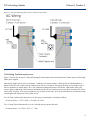
Distributing 3-phase power to the enclosure
There are two 3-phase feeds for the c7000 enclosure. They are marked on the input module as A and B, respectively. Feed A
supplies power supplies 1, 2, and 3 while feed B supplies power supplies 4, 5, and 6.
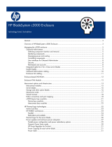
As with all ProLiant servers that use AC power, the power supplies themselves use single phase current. Figure 2-1 illustrates
that with the 3-phase c7000 enclosure, each power supply is connected to a single phase of the 208V (North America) or
230V (International) 3-phase feed.
Resource description Web address
I/O Virtualization and Sharing
http://www.pcisig.com/developers/main/training_materials/get_document
?doc_id=0cd682cb65b452d00e2047287b48369fc0d9bfa6
HP Virtual Connect Technology
http://h18004.www1.hp.com/products/blades/virtualconnect/index.html
HP Flex-10 Technology
http://h20000.www2.hp.com/bc/docs/support/SupportManual/c016089
22/c01608922.pdf
Flex-10 VC Ethernet Module
http://h18004.www1.hp.com/products/blades/components/ethernet/10-
10gb-f/index.html
HP NC532m Dual Port Flex-10 10GbE
http://h18004.www1.hp.com/products/servers/networking/nc532m/inde
x.html?jumpid=reg_R1002_USEN
Implementing PCI I/O Virtualization
Standards
http://download.microsoft.com/download/a/f/d/afdfd50d-6eb9-425e-
84e1-b4085a80e34e/SYS-T311_WH07.pptx
10 Gigabit Ethernet technology for industry-
standard servers, 2nd edition
http://h20000.www2.hp.com/bc/docs/support/SupportManual/c01608915/c0
1608915.pdf

ISS Technology Update Volume 8, Number 3
4
Figure 2-1. Physically mapping 3-phase power to c7000 AC input module.
Calculating 3-phase input power
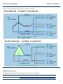
Figure 2-2 shows how the power is electrically mapped for both North America and International 3-phase power into the single-
phase power supplies.
International 3-phase power uses five conductors, including a true neutral conductor, allowing each of individual phases to
deliver the full 230 volts. North American 3-phase power uses four conductors. The neutral conductor for one phase is one of
the line conductors for another phase. Thus, only a differential voltage and not the full 208 volts is delivered to each of the
power supplies. Additionally, North American standards state that circuits should not continuously draw more than 80% of their
rated current. Therefore, a 30 Amp circuit delivers only 24 Amps continuously. All of this must be taken into consideration when
calculating the total input power from 3-phase circuits.
For a 30 Amp, 3-phase North American circuit, the input power delivered is calculated as follows:
Continuous power = 1.732 x 208V x (.8 x 30A) = 8.6 kVA
For a 16 Amp 3-phase International circuit, this would be the input power delivered:
Continuous power = 3 x 230V x 16A = 11.1 kVA

ISS Technology Update Volume 8, Number 3
5
Figure 2-2. Electrical diagrams of 3-phase power to a c7000 AC input module
Additional resources
For additional information on the topics discussed in this article, visit this website:
Resource URL
HP BladeSystem c7000 Enclosure http://h18004.www1.hp.com/products/blades/components/enclosures/c-class/c7000/

ISS Technology Update Volume 8, Number 3
6
PUE and DCE—Useful metrics for overall data center efficiency
IT and facilities engineers can use two metrics to evaluate data center energy efficiency: Power Use Efficiency (PUE) and Data
Center Efficiency (DCE). PUE and DCE are not intended to measure the efficiency of specific power and cooling systems within
data center infrastructures. Rather, they are useful as “field” metrics to quantify overall data center efficiency.
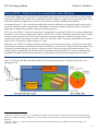
As illustrated in Figure 3-1, PUE is the total power delivered to the facility divided by the net power that goes directly to the IT
equipment. PUE can be used by an organization to benchmark its data center operations against the industry. It also offers a
simple metric for determining compliance with governmental energy policies.
DCE—the inverse of PUE—is an alternative metric that is represented as a percentage. The DCE of a non-optimized data center
may be 60%, while an optimized data center could have a DCE of 75% or higher.
1
Research by the Uptime Institute
2
indicates
that 85% of data centers consume 2 kW for each kW used by IT equipment, with only a small portion going to power
conditioning/conversion. This energy use results in a PUE of 3, and yields a DCE of 33 percent, meaning that only one-third of
facility power is consumed by IT equipment (Figure 3-1 right).
Data centers with a PUE of 3 or greater typically have a grossly over-provisioned cooling system. Over-provisioning increases
capital and recurring expenses and decreases utilization and efficiency, which results in a higher total cost of ownership (TCO).
Consequently, alternate strategies are required to isolate root causes of inefficiency and provide remedial solutions. These
strategies range from adopting the latest best practices for high-density computing platforms to creating a management layer
that enables consolidation and an infrastructure that can dynamically provision power and cooling resources as needed.
Figure 3-1. PUE is the total data center load divided by the power that goes directly to IT equipment. DCE is the inverse
percentage of PUE.
1
Aebischer, B. Eubank, H., Tschudi, W., “Energy Efficiency Indicators for Data Centers,“ International Conference on Improving Energy
Efficiency in Commercial Buildings “IEECB’04”, 21 - 22 April 2004, Frankfurt (Germany). DCE is equivalent to CEE (Coefficient of Energy
Efficiency).
2
Belady, C., Malone, C., "Metrics to Characterize Data Center & IT Equipment Energy Use," Digital Power Forum, Richardson, TX
(September, 2006).

ISS Technology Update Volume 8, Number 3
7
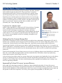
Meet the Expert—Wayne Vuong
Wayne Vuong has been an Engineering Program Manager with Industry Standard
Servers (ISS) for the last three years of his 12-year career at HP. Wayne has
distinguished himself because of his hard work and passion for getting customer
input to engineering teams so they can incorporate it into their design decisions.
Engineering was a natural progression for Wayne because even at an early age
he was very analytical, creative, and detail oriented. He enjoys puzzles and math
problems. His favorite pastimes are fishing, billiards, card games, and playing the
piano. He and his wife, Yisel, have a 4-year old son, Jonathan, who is well
protected by their 12-year old beagle, Maggie.
A passion for customer input
Wayne is highly regarded for his support of the ISS Technical Advisory Committee
(TAC), a professional social network that facilitates interaction between HP
customers and ISS technologists. According to his manager, Jeoff Krontz,
“Wayne’s involvement with TAC yielded excellent customer feedback that affected
product decisions.” In fact, Wayne says that almost all product design decisions
are a result of customer feedback received from marketing, management, and
direct customer visits.
Helping drive the Common Design effort
Wayne also architected the successful Common Design process that has been implemented in fifth-generation (G5) and G6
ProLiant servers, and led the Common Design team for G5 and midway into G6. The Common Design effort creates a server
schematic that is directly shared by most ProLiant design teams, significantly increasing design quality and efficiencies.
Synchronizing all platforms with the same proven design virtually eliminates design errors that may occur if, for example, one
platform intentionally or unintentionally implements a circuit differently. The Common Design effort also prevents communication
errors or breakdowns where information may not be disseminated properly, which can result in a platform having a design
quality issue.
Wayne says that getting the Common Design process to work was very challenging because many believed that it could not be
done. Also, various hurdles kept appearing that could have derailed the effort. Nevertheless, Wayne kept implementing
workarounds to keep the Common Design vision alive.
In the end, having server platform teams use common designs gave many engineers more bandwidth to focus on other design
activities. As these design activities were finished, they were also automatically incorporated by the other platform teams
through the Common Design effort. This further reduced the design effort expended by each platform team, resulting in even
more free engineering bandwidth.
Impressed by ProLiant G6 servers’ power efficiency
When asked which technologies exemplify HP’s leadership, Wayne remarked that the ability of ProLiant G6 servers to
dynamically balance power efficiency with performance through HP iLO (Onboard Administrator) is phenomenal. Power and
thermal controls embedded into Onboard Administrator reduce server power consumption by regulating processor speed and
the operation of other server components, such as fans, power supplies, and unpopulated I/O and memory slots.
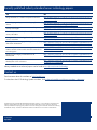
Name: Wayne Vuong
Title: Engineering Program Manager, ISS
Years at HP: 12
University: BSEE, Rice University
MEE, Rice University
U.S. Patents: 2
Name: Wayne Vuong
Title:
Engineering Program Manager, ISS
Years at HP: 12
University: BSEE, Rice University
MEE, Rice University
U.S. Patents: 2

Legal Notices© Copyright 2009 Hewlett-Packard Development Company, L.P. The information contained herein is
subject to change without notice. The only warranties for HP products and services are set forth in the express
warranty statements accompanying such products and services. Nothing herein should be construed as constituting
an additional warranty. HP shall not be liable for technical or editorial errors or omissions contained herein.
TC090411NL
April 2009
Recently published industry standard server technology papers
Title URL
Using InfiniBand for a Scalable Compute Infrastructure
http://h20000.www2.hp.com/bc/docs/support/SupportManual/c00593
119/c00593119.pdf
Power Capping and Dynamic Power Capping for ProLiant
Servers
http://h20000.www2.hp.com/bc/docs/support/SupportManual/c01549
455/c01549455.pdf?jumpid=reg_R1002_USEN
Memory technology evolution: an overview of system
memory technologies
http://h20000.www2.hp.com/bc/docs/support/SupportManual/c0
0256987/c00256987.pdf
The Intel® processor roadmap for industry-standard
servers, 9th Edition
http://h20000.www2.hp.com/bc/docs/support/SupportManual/c00164
255/c00164255.pdf
10 Gigabit Ethernet technology for industry-standard
servers, 2nd edition
http://h20000.www2.hp.com/bc/docs/support/SupportManual/c01608
915/c01608915.pdf
Converged fabrics: Emerging technologies for simplifying
data center infrastructure
http://h20000.www2.hp.com/bc/docs/support/SupportManual/c0
1681871/c01681871.pdf
Data security in HP ProLiant servers using the Trusted
Platform Module and Microsoft® Windows ® BitLocker™
Drive Encryption
http://h20000.www2.hp.com/bc/docs/support/SupportManual/c0
1681891/c01681891.pdf
Electrical signal integrity considerations for HP
BladeSystem
http://h20000.www2.hp.com/bc/docs/support/SupportManual/c0
1712559/c01712559.pdf
Delivering an Adaptive Infrastructure with the HP
BladeSystem c-Class architecture
http://h20000.www2.hp.com/bc/docs/support/SupportManual/c0
1720656/c01720656.pdf
Industry standard server technical papers can be found at www.hp.com/servers/technology.
Contact us
Send comments about this newsletter to [email protected].
To subscribe to the ISS Technology Update newsletter, click
mailto:techcom@hp.com?subject=newsletter_subscription
-
 1
1
-
 2
2
-
 3
3
-
 4
4
-
 5
5
-
 6
6
-
 7
7
-
 8
8


Compaq DL360 - ProLiant - Photon User manual
- Type
- User manual
Ask a question and I''ll find the answer in the document
Finding information in a document is now easier with AI
Related papers
-
Compaq BL20p - ProLiant - G2 User manual
-
-
Compaq BL10e - HP ProLiant - 512 MB RAM Introduction Manual
-
Compaq BL260c - ProLiant - G5 Introduction Manual
-
-
-
-
-
-
Other documents
-
HP Data Center Environmental Edge Important information
-
 StarTech.com C3000 User manual
-
HP (Hewlett-Packard) xw460c blade workstation User manual
-
-
-
-
-
-
-
Shimano SG-C7050-5V User manual
