Page is loading ...

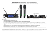
UHF Wireless Microphone System
PDWM1902 • PDWM1904 • PDWM3375 • PDWM3378 • PDWM3400

www.PyleUSA.com
1
SYSTEM TYPE
• The Vocal Artist-UHF is a hand-held system designed for singers who desire the
high quality microphones and the freedom of wireless performance.
• The Presenter-UHF is a body-pack system designed for public speakers who prefer
an inconspicuous, hands-free lavaliere microphone.
• The Headset-UHF is a body-pack system designed for users in physically active
applications, who desire the freedom of hand-free microphone.
• System Operating frequency range is: 573-597.8 MHz.
CHANNEL RECEIVER
SINGLE CHANNEL RECEIVER
1. Power Button: Power ON/OFF the receiver.
2. Power Indicator: Indicate the power ON/OFF.
3. Channel Display: Indicates the frequency data of the selected channel group.
4. SET Function Button: Sets channel data.
5. "AF" Audio Level Indicator: Indicate the wireless system audio signal level.
6. "RF" Signal indicator: Glows when the Receiver receive RF signal from Transmitter.
7. Antenna.
8. Volume Knob: Adjust the volume output of receiver.
9. XLR Balanced Output Jack: Connect the audio cable from this jack to the input
port of amplier, mixer.
10. 1/4" Audio Output Jack: Connect the audio cable from this jack to the input
port of amplier, mixer.
11. Power Jack: Connect the AC/DC adapter to receiver.

www.PyleUSA.com
2
DUAL CHANNEL RECEIVER
1. Power Button: Power ON/OFF the receiver.
2. Power Indicator: Indicate the power ON/OFF.
3. Channel Display: Indicates the frequency data of the selected channel group.
4. SET Function Button: Sets channel data.
5. "AF"Audio Level Indicator: Indicate the wireless system audio signal level.
6. "RF" Signal indicator: Glows when the Receiver receive RF signal from Transmitter.
7. Antenna.
8. Volume Knob: Adjust the volume output of receiver.
9. XLR Balanced Output Jack: Connect the audio cable from this jack to the input
port of amplier, mixer.
10. 1/4" Audio Output Jack: Connect the audio cable from this jack to the input
port of amplier, mixer.
11. Power Jack: Connect the AC/DC adapter to receiver.

www.PyleUSA.com
3
MICROPHONE FUNCTIONS
1. Grille: Protects the cartridge and help reducing the breath sounds and wind noise.
2. Channel Display: Indicates the frequency data of the selected channel group.
3. Down Function Button: Sets channel data.
4. Up Function Button: Sets channel data.
5. Power and Audio Mute Switch.
6. Battery Cover: Open it to install the battery.
TRANSMITTER FUNCTIONS

www.PyleUSA.com
4
1. Power and Audio Mute Switch.
2. Antenna: Transmit the RF signal of transmitter.
3. Belt Clip: Attach the transmitter to the belt.
4. Audio Input Jack: It is suitable for lavalier system/headset system.
5. Channel Display: Indicates the frequency data of the selected channel group.
6. Gain Adjusting Volume: Adjust the transmitter audio input gain.
7. State Setting Switch: Set the using state of lavalier system (L) / headset system (H).
8. Up Function Button: Sets channel data.
9. Down Function Button: Sets channel data.
RECEIVER CONNECTIONS
1. Receiver Power Connection: Connect the AC adapter into the DC power
connector on the back of the receiver. Plug the AC adapter into a AC 120V/220V
50Hz outlet.
2. Antenna: Keep the position of antenna at a 45 angle from vertical.
(Shown as below)
3. Audio Connection: Connect the audio cable from the audio output on the
receiver to the input on your amplier equipment.

www.PyleUSA.com
5
BODYPACK TRANSMITTER CONNECTION
1. Lavalier Microphone Connection: Connect the connector of supplied Lavalier
microphone to the connecting jack of transmitter (Shown as below) Set the
transmitter work state in wireless lavaliere system.
2. Headset Microphone Connection: Connect the connector of supplied Headset
microphone to the connecting jack of transmitter (Shown as below) Set the
transmitter work state in wireless headset system.
TRANSMITTER BATTERY INSTALLATION
1. Battery Installation of Transmitter: Push open the battery cover. Insert the
supplied batteries into battery jar in polarity and cover the battery Cover.
MATCHINGWIRELESS FREQUENCY (RECEIVER /TRANSMITTER CONNECTION)
1. Press and hold the “SET” button on the receiver --- then release the button once
the receiver display begins to ash.
2. When it is ashing, continue to press the “SET” button again to select the desired
channel, the selected channel will save automatically without any action for 5
seconds.
3. Power on your microphone/transmitter, press and hold the “UP” and “DOWN”
arrow keys once the CH number on display begins to ash.
4. When it is ashing, press “UP” and “DOWN” arrow keys to select the same channel
as chosen on receiver, then, the selected channel will save automatically without
any action for5 seconds.
5. Repeat steps 1-4 to connect an additional microphone / transmitter (For models
PDWM3375, PDWM3400)

www.PyleUSA.com
6
PROBLEM INDICATOR STATUS
No Sound
Rod transmitter
Slide transmitter POWER ON/
OFF switch ON position. Make
sure battery Is Inserted properly,
observing battery (+/-), If battery
is inserted properly, replace with
fresh battery.
Rod transmitter
Slide transmitter MUTE/ON
switch ON position.
Red receiver POWER light off
Make sure AC adapter is securely
plugged into a electrical outlet
and into DC input connector.
Make sure AC electrical outlet
works and supplies proper volt-
age.
Receiver signal indicators
A/B lights glowing
Turn up receiver volume control.
-
tions from the receiver to the
external equipment are secure.
Receiver signal indicators A/B
lights off. Transmitter and receiv-
er POWER lights glowing.
receiver’s frequencies matches.
Move transmitter closer to the
receiver.
Sound level differs from level of
cabled instrument
Receiver signal indicators A/B
lights glowing
Adjust transmitter gain level to
compensatory.
Adjust receiver volume as
necessary.
Sound level differs with different
guitars.
Receiver signal indicators A/B
lights glowing.
Re-adjust transmitter gain level
to compensate for differences in
guitar outputs.
Distortion level increases
gradually
Receiver signal indicators
A/B
lights and transmitter’s low bat
-
tery light glowing
Replace transmitter battery
Bursts of noise or other audible
radio signals present
Signal indicators A/B lights on
Identify potential sources of
interference (other RF sources)
and turn off, remove or use a
wireless system operating on a
different frequency.
Momentary loss of sound as
transmitter is moved around
performing area
Receiver signal indicators A/B
lights off when sound is lost.
Reposition receiver and perform
walk-through test again. If
audio
dropouts persist, mark “dead“
spots and avoid them during
performance
TROUBLESHOOTING
SOLUTION

www.PyleUSA.com
7
UHF WIRELESS MICROPHONE SYSTEM
FEATURES AND SPECIFICATIONS
PDWM1902
System Features:
• UHF Microphone Signal Transmission
• Simple Setup & Hassle-Free Operation
• Operation Range: Up to 160'+ ft.
• LED Display for Channel Display & Power Indicator
• Selectable Frequency: (8) Available Audio Channels
• Audio Level Indicator: Displays Wireless Signal Strength
• RF Signal Indicator: Displays Transmitter Signal Strength
• Adjustable Rotary Volume Control
• 1/4" Audio Output Jack
• XLR Balanced Output Jack
Handheld Microphone Specs:
• Includes (1) Wireless Dynamic Mic
• LCD Display with Channel Readout
• RF Output: >10 dBm
• Modulation Type: FM
• Max Deviation: ±40 KHz
• Spurious Emission: >55 dBc
• Nominal Current Drain: < 40mA
• Battery Operated, Requires: (2) x 'AA' Batteries
• Dimensions: 9.25 x 1.9 x 1.9 in
Receiver Specs:
• Image & Spurious Rejection: >70 dB
• Signal / Noise Ratio: -105dB
• T.H.D.: < 1%
• Audio Output Level: 0-300 mV
• Power Supply: 110/220V (12-15V Power Adapter)
• Dimensions: 6.8 x 5.3 x 1.7 in
• Sold as: Kit
• Weight: 2.62 lbs.

www.PyleUSA.com
8
PDWM1904
System Features:
• UHF Band Microphone System
• Simple Setup & Hassle-Free Operation
• Operation Range: Up to 160'+ ft.
• LED Display Screens for Audio Channel & Power Indicator
• Audio Level Indicator: Displays Wireless Audio Signal Strength
• RF Signal Indicator: Display Transmitter Signal Strength
• Adjustable Rotary Volume Control
• 1/4'' Audio Output Jack
• XLR Balanced Output Jack
What's in the Box:
• Microphone Receiver
• (1) Body-Pack Transmitter
• (1) Headset Mic
• (1) Lavalier Mic
Body-Pack Transmitter Specs:
• RF Output: >10 dBm
• Modulation Type: FM
• Max Deviation: ± 40 KHz
• Spurious Emission: > 55 dBc
• Nominal Current Drain: < 40mA
• Power Requirements: 2 x 1.5V AA
Receiver Specs:
• Signal / Noise Ratio: -105dB
• Border Upon Channel Rejection: > 70 dB
• T.H.D.: < 1%
• Audio Output Level: 0-300 mV
• Power Supply: 110/220V (12-15V Power Adapter)
• Dimensions 6.8 x 5.3 x 1.7 in
• Sold as: Kit
• Weight: 2.5 lbs.

www.PyleUSA.com
9
PDWM3375
System Features:
• UHF Band Microphone System
• Simple Setup & Hassle-Free Operation
• Operation Range: Up to 160'+ ft.
• LED Screen Displays Audio Channel & Power Indicator
• Audio level indicator for wireless signal
• RF Signal Indicator for transmitter signal strength
• Independent & adjustable channel volume controls
• Selectable Frequency Range: Up to (8) Channels
• 1/4" Audio Output Jack
• XLR Balanced Output Jack
Receiver Specs:
• Signal / Noise Ratio: -105dB
• Border Upon Channel Rejection: >70dB
• T.H.D.: < 1%
• Audio Output Level: 0-300 mV
• Dimensions 6.8 x 5.3 x 1.7 in
Handheld Mic Specs:
• Includes (2) Wireless Dynamic Microphones
• RF Output: >10 dBm
• Modulation Type: FM
• Max Deviation: ± 40 KHz
• Spurious Emission: > 55 dBc
• Nominal Current Drain: < 40mA
• Battery Powered, Requires (2) x 'AA' Batteries -Each
• Dimensions: 9.25 x 1.9 x 1.9 in
• Power Supply: 110/220V (12-15V Power Adapter)
• Sold as: Kit
• Weight: 3.12 lbs.

www.PyleUSA.com
10
PDWM3378
System Features:
• UHF Band Microphone System
• Operation Range: Up to 160'+ ft.
• LED Digital Display Readout Screens
• Simple Setup & Hassle-Free Operation
• AF & RF Audio Transmission Signal Strength Indicators
• Independent & Adjustable Channel Volume Controls
• Selectable Frequency Range: Up to (8) Channels
• 1/4" Audio Output Jack
• XLR Balanced Output Jack
What's in the Box:
• Receiver Base
• Belt pack Transmitter
• Hand held Microphone
• Headset Microphone
• Lavalier Microphone
• Power Cable
Transmitter Specs:
• RF Output: >10 dBm
• Modulation Type: FM
• Max Deviation: ± 40 KHz
• Spurious Emission: > 55 dBc
• Nominal Current Drain: < 40mA
• Battery Powered, Requires (2) x 'AA' Batteries -Each
Receiver Specs:
• Signal / Noise Ratio: -105dB
• Border Upon Channel Rejection: >70dB
• T.H.D.: < 1%
• Audio Output Level: 0-300 mV
• Dimensions 6.8 x 5.3 x 1.7 in
• Power Supply: 110/220V (12-15V Power Adapter)
• Sold as: 1

www.PyleUSA.com
11
PDWM3400
System Features:
• UHF Band Microphone Signal System
• Operation Range: Up to 160'+ ft.
• Audio Level Indicator for Wireless Signal Strength
• Independent & Adjustable Channel Volume Controls
• RF Signal Indicator for Transmitter Signal Strength
• LED Power Indicator & Channel Display
• Selectable Frequency Range: Up to (8) Channels
• 1/4'' Audio Output Jack
• XLR Balanced Output Jack
What's in the Box:
• Microphone Receiver
• (2) Body-Pack Transmitters
• (2) Headset Microphones
• (2) Lavalier Microphones
Body-Pack Transmitter Specs:
• RF Output: >10dBm
• Modulation Type: FM
• Max Deviation: ±40KHz
• Spurious Emission: >55dBc
• Nominal Current Drain: <40mA
• Power Requirements: (2) x 1.5V AA (Not Included)
• Dimensions: 9.25'' x 1.9'' x 1.9''
Receiver Specs:
• Image & Spurious Rejection: >70 dB
• Signal / Noise Ratio: -105dB
• T.H.D.: < 1%
• Audio Output Level: 0-300 mV
• Power Supply: 110/220V (12-15V, DC Adapter)
• Dimensions 6.8'' x 5.3'' x 1.7''
• Sold as: Kit
• Weight: 2.94 lbs.

www.PyleUSA.com
12
PDWM1902 PDWM1904
PDWM3375 PDWM3378
PDWM3400

/