American Dryer AD-200 User manual

Category
Electric laundry dryers
Type
User manual
ADC Part No. 450310
American Dryer Corporation
88 Currant Road
Fall River, MA 02720-4781
Telephone: (508) 678-9000 / Fax: (508) 678-9447
e-mail: techsupport@amdry.com
062599DMG/cms
AD-200 Service Manual
with Non-Tilt Options
1993 thru 1998
Retain This Manual In A Safe Place For Future Reference
American Dryer Corporation products embody advanced concepts in engineering, design, and safety. If this
product is properly maintained, it will provide many years of safe, efficient, and trouble-free operation.
ONLY properly licensed technicians should service this equipment.
OBSERVE ALL SAFETY PRECAUTIONS displayed on the equipment or specified in the installation/operator's
manual included with the dryer.
WARNING: UNDER NO CIRCUMSTANCES should the door switch or the heat circuit devices
ever be disabled.
WARNING: The dryer must never be operated with any of the back guards, outer tops, or
service panels removed. PERSONAL INJURY or FIRE COULD RESULT.
We have tried to make this manual as complete as possible and hope you will find it useful. ADC reserves the
right to make changes from time to time, without notice or obligation, in prices, specifications, colors, and material,
and to change or discontinue models.
Important
For your convenience, log the following information:
Replacement parts can be obtained from your distributor or the ADC factory. When ordering replacement parts
from the factory, you can FAX your order to ADC at (508) 678-9447 or telephone your orders directly to the
ADC Parts Department at (508) 678-9010. Please specify the dryer model number and serial number in
addition to the description and part number, so that your order is processed accurately and promptly.
The illustrations on the following pages may not depict your particular dryer exactly. The illustrations are a
composite of the various dryer models. Be sure to check the descriptions of the parts thoroughly before ordering.
INSTRUCTIONS TO BE FOLLOWED IN THE EVENT THE USER
SMELLS GAS MUST BE POSTED IN A PROMINENT LOCATION. THE
INSTRUCTIONS TO BE POSTED SHALL BE OBTAINED FROM THE
LOCAL GAS SUPPLIER.
DATE OF PURCHASE MODEL NO.
DISTRIBUTORS NAME
Serial Number(s)
AD-200 Non-Tilting
IMPORTANT
YOU MUST DISCONNECT and LOCKOUT THE ELECTRIC
SUPPLY and THE GAS SUPPLY or THE STEAM SUPPLY BEFORE ANY
COVERS or GUARDS ARE REMOVED FROM THE MACHINE TO
ALLOW ACCESS FOR CLEANING, ADJUSTING, INSTALLATION, or
TESTING OF ANY EQUIPMENT per OSHA (Occupational Safety and Health
Administration) STANDARDS.
WARNING
The dryer must never be operated with any of the back guards, outer
tops, or service panels removed. PERSONAL INJURY or FIRE COULD
RESULT.
CHILDREN SHOULD NOT BE ALLOWED TO PLAY ON OR NEAR
THE DRYER(S).
WARNING
CHILDREN SHOULD BE SUPERVISED IF NEAR DRYER(S) IN
OPERATION.
CAUTION
LABEL ALL WIRES PRIOR TO DISCONNECTION WHEN SERVICING
CONTROLS. WIRING ERRORS CAN CAUSE IMPROPER AND DANGER-
OUS OPERATION.
DRYER(S) SHOULD NEVER BE LEFT UNATTENDED WHILE IN
OPERATION.
CAUTION
VERIFY PROPER OPERATION AFTER SERVICING.
DO NOT STORE OR USE GASOLINE OR OTHER FLAMMABLE
VAPOR AND LIQUIDS IN THE VICINITY OF THIS OR ANY OTHER
APPLIANCE.
FOR YOUR SAFETY
DO NOT DRY MOP HEADS IN THE DRYER.
DO NOT USE DRYER IN THE PRESENCE OF DRY CLEANING FUMES.
IMPORTANT
PLEASE OBSERVE ALL SAFETY PRECAUTIONS displayed on the
equipment and/or specified in the installation/operator's manual included with
the dryer.
Dryer(s) must not be installed or stored in an area where it will be exposed to
water and/or weather.
The wiring diagram for the dryer is located in the front electrical control box
area.
Table of Contents
SECTION I
SAFETY PRECAUTIONS..........................................................................................2
SECTION II
ROUTINE MAINTENANCE...................................................................................... 4
SECTION III
SPECIFICATIONS and DIMENSIONS ..................................................................... 8
SECTION IV
INSTALLATION REQUIREMENTS.........................................................................9
SECTION V
COMPONENT DESCRIPTION ...............................................................................11
SECTION VI
BASIC TROUBLESHOOTING ................................................................................58
SECTION VII
ELECTRICAL TROUBLESHOOTING...................................................................65
SECTION VIII
PHASE 5 OPL SYSTEM DIAGNOSTICS..............................................................74
2
SECTION I
SAFETY PRECAUTIONS
CAUTION: The dryer should never be left unattended while in operation.
WARNING: For your safety, the information in this manual must be followed to minimize the
risk of fire or explosion or to prevent property damage, personal injury, or loss of
life.
WARNING: The dryer must never be operated with any of the back guards, outer tops, or
service panels removed. PERSONAL INJURY or FIRE COULD RESULT.
1. DO NOT store or use gasoline or other flammable vapors and liquids in the vicinity of this or any
other appliance.
2. Purchaser/user should consult the local gas supplier for proper instructions to be followed in the
event the user smells gas. The instructions should be posted in a prominent location.
3. WHAT TO DO IF YOU SMELL GAS...
a. DO NOT try to light any appliance.
b. DO NOT touch any electrical switch.
c. DO NOT use any phone in your building.
d. Clear the room, building, or area of ALL occupants.
e. Immediately call your gas supplier from a neighbor's phone. Follow the gas supplier's instructions.
f. If you cannot reach your gas supplier, call the fire department.
4. Installation and service must be performed by a qualified installer, service agency, or gas supplier.
5. Dryers must be exhausted to the outdoors.
6. Although ADC produces a very versatile machine, there are some articles that, due to fabric
composition or cleaning method, should not be dried in it.
WARNING: Dry only water-washed fabrics. DO NOT dry articles spotted or washed in dry
cleaning solvents, a combustible detergent, or "all purpose" cleaner. EXPLOSION
COULD RESULT.
WARNING: DO NOT dry rags or articles coated or contaminated with gasoline, kerosene, oil,
paint, or wax. EXPLOSION COULD RESULT.
3
WARNING: DO NOT dry mop heads. Contamination by wax or flammable solvent will create a
fire hazard.
WARNING: DO NOT use heat for drying articles that contain plastic, foam, sponge rubber, or
similarly textured rubberlike materials. Drying in a heated basket (tumbler) may
damage plastics or rubber and also may be a fire hazard.
7. A program should be established for the inspection and cleaning of lint in the burner area, exhaust duct
work, and area around the back of the dryer. The frequency of inspection and cleaning can best be determined
from experience at each location.
WARNING: The collection of lint in the burner area and exhaust duct work can create a potential
fire hazard.
8. For personal safety, the dryer must be electrically grounded in accordance with local codes
and/or the NATIONAL ELECTRIC CODE ANSI/NFPA NO. 70-LATEST EDITION.
NOTE: Failure to do so will VOID THE WARRANTY.
9. UNDER NO CIRCUMSTANCES should the dryer door switches, lint drawer switch, or heat safety
circuit, ever be disabled.
WARNING: PERSONAL INJURY or FIRE COULD RESULT.
10. This dryer is not to be used in the presence of dry cleaning solvents or fumes.
11. Remove articles from the dryer as soon as the drying cycle has been completed.
WARNING: Articles left in the dryer after the drying and cooling cycles have been complete can
create a fire hazard.
12. READ and FOLLOW ALL CAUTION and DIRECTION LABELS ATTACHED TO THE
DRYER.
WARNING: YOU MUST DISCONNECT and LOCKOUT THE ELECTRIC SUPPLY
and THE GAS SUPPLY or THE STEAM SUPPLY BEFORE ANY COVERS
or GUARDS ARE REMOVED FROM THE MACHINE TO ALLOW
ACCESS FOR CLEANING, ADJUSTING, INSTALLATION, or TESTING
OF ANY EQUIPMENT per OSHA (Occupational Safety and Health
Administration) STANDARDS.
IMPORTANT: Label ALL wires prior to disconnection when servicing the microprocessor
controller (computer) and the ignition module. WIRING ERRORS CAN
CAUSE IMPROPER and DANGEROUS OPERATION.
4
SECTION II
ROUTINE MAINTENANCE
A. CLEANING
A program and/or schedule should be established for periodic inspection, cleaning, and removal of lint from
various areas of the dryer, as well as throughout the duct work system. The frequency of cleaning
can best be determined from experience at each location. Maximum operating efficiency is dependent
upon proper air circulation. The accumulation of lint can restrict this air flow. If the guidelines in this
section are met, an ADC dryer will provide may years of efficient, trouble-free, and - most importantly -
safe operation.
WARNING: LINT FROM MOST FABRICS IS HIGHLY COMBUSTIBLE. THE
ACCUMULATION OF LINT CAN CREATE A POTENTIAL FIRE
HAZARD.
WARNING: KEEP DRYER AREA CLEAR AND FREE FROM COMBUSTIBLE
MATERIALS, GASOLINE, and OTHER FLAMMABLE VAPORS and
LIQUIDS.
NOTE: REMOVE POWER FROM THE MACHINE BEFORE PERFORMING ANY
MAINTENANCE IN THE MACHINE.
NOTE: Suggested time intervals shown are for average usage which is considered six (6) to eight
(8) operational (running) hours per day.
SUGGESTED CLEANING SCHEDULE
EVERY THIRD or FOURTH LOAD
Clean the lint basket. A clogged lint basket will cause poor dryer performance. The lint basket is
located in the lint drawer in the base of the dryer. Pull out the lint drawer, brush the lint off the lint
basket, and remove the lint. Inspect the lint screen and replace if torn.
NOTE: The frequency of cleaning the lint screens can best be determined from experience at
each location.
WEEKLY
Open the hinged panels on each side of the tumbler section and remove any lint accumulation from the
tumbler drive motor, drive shafts, drive wheels, and drive shaft bearings.
Slide the lint basket all the way out of the dryer and clean any lint accumulation off of the temperature
sensor bracket, which is located above the lint basket.
5
WARNING: TO AVOID THE HAZARD OF ELECTRICAL SHOCK, DISCONTINUE
ELECTRICAL SUPPLY TO THE DRYER.
MONTHLY
Empty the compressed air filter bowl.
Clean any lint accumulation from the gas valve/burner area at the top of the dryer, the fan (impellor)
motor, and the fan (impellor) bearings located in the dryer base.
EVERY 6 MONTHS
STEAM MODELS - clean the steam coil fins. We suggest using compressed air and a vacuum cleaner
with brush attachment.
NOTE: When cleaning steam coil fins, be careful not to bend the fins. If fins are bent,
straighten by using a fin comb, which is available from any local air conditioning supply
house.
Inspect and remove any lint accumulation in customer furnished exhaust duct work system and from
the dryers internal exhaust ducting.
NOTE: THE ACCUMULATION OF LINT IN THE EXHAUST DUCT WORK CAN
CREATE A POTENTIAL FIRE HAZARD.
NOTE: DO NOT OBSTRUCT THE FLOW OF COMBUSTION and VENTILATION AIR.
CHECK CUSTOMER FURNISHED BACK DRAFT DAMPERS IN THE EXHAUST
DUCT WORK. INSPECT and REMOVE ANY LINT ACCUMULATION WHICH
CAN CAUSE THE DAMPER TO BIND or STICK.
NOTE: When cleaning the dryer cabinet(s), avoid using harsh abrasives. A product Intended for
the cleaning of appliances is recommended.
Clean off any lint accumulation on top of the temperature probe and the hi-limit switch located above the lint
basket.
6
B. LUBRICATION
MONTHLY
Check compressed air filter bowl for water. Empty by pressing the rubber petcock to the side. Additionally,
check lubricator bowl for oil. If empty, remove the fill plug and add oil. (Use petroleum based 10/150 SSU
misting oil.) Replace fill plug.
NOTE: LUBRICATOR SHOULD BE SET AT 1 DROP PER CYCLE.
NOTE: REGULATOR PRESSURE IS TO BE SET AT 80 PSI.
Apply high temperature grease to the four (4) 1-1/2" diameter tumbler drive shaft pillow block bearings and
the two (2) 1-3/8" diameter blower shaft pillow block bearings. (Use Shell Alvania #3 grease or equivalent.)
MAN3203
7
C. ADJUSTMENTS
7 DAYS AFTER INSTALLATION and EVERY 6 MONTHS THEREAFTER
Inspect bolts, nuts, screws, (bearing set screws), nonpermanent gas connections (i.e., unions, shut-off valves,
orifices), and grounding connections. Fan (impellor) V-belts, along with the motor and drive belts should
be examined and replaced if necessary. Tighten loose V-belts when necessary. Complete operational check
of controls and valves. Complete operational check of ALL safety devices (i.e., door switches, lint drawer
switch, sail switch, burner and hi-limit thermostats).
8
SECTION III
SPECIFICATIONS and DIMENSIONS
A. SPECIFICATIONS (Gas and Steam Models)
NOTE: ADC reserves the right to make changes in specifications at any time, without notice or
obligation.
Gas*
Steam*
M
AXIMUM
C
APACITY
(
DRY
WEIGHT
)200 lbs.
90.9 kg
B
ASKET
(
TUMBLER
) D
IAMETER
62-1/2"
158.75 cm
B
ASKET
(
TUMBLER
) D
EPTH
42"
106.7 cm
B
ASKET
(
TUMBLER
) V
OLUME
74.5 cu. ft.
2.11 cu.m.
D
RIVE
M
OTOR
3 HP
2.24 kw
B
LOWER
M
OTOR
(
GAS
/
STEAM
) 7-1/2 HP/15 HP
5.6 kw/11.2 kw
D
OOR
O
PENING
36-3/4" W
IDE
x 43" H
IGH
93.3 cm x 109.2 cm
D
OOR
S
ILL
H
EIGHT
-
LEVEL
37-1/4"
94.6 cm
C
OMPRESSED
A
IR
80 PSI
5.63 kg/cu.m.
C
OMPRESSED
A
IR
C
ONNECTION
3/8" F.P.T.
.953 cm
V
OLTAGE
A
VAILABLE
208-460v / 3ø / 3, 4w / 50/60 Hz
H
EAT
I
NPUT
750,000 btu/hr
189,000 kcal/hr
A
PPROX
. W
EIGHT
(
UNCRATED
) 3,369 lbs.
1,528 kg
A
IRFLOW
5,300 cfm
150 cmm
Inlet Pipe Size 1-1/4"
3.18 cm
V
OLTAGE
A
VAILABLE
208-460v / 3ø / 3, 4w / 50/60 Hz
A
PPROX
. W
EIGHT
(
UNCRATED
) 3,719 lbs.
1,687 kg
A
IRFLOW
6,500 cfm
184 cmm
S
TEAM
C
OMSUMPTION
B
OILER
HP
N
ORMAL
L
OAD
890 lbs/hr
404.5 kg/hr
27
O
PERATING
S
TEAM
P
RESSURE
S
TEAM
S
UPPLY
S
TEAM
R
ETURN
125 psi max
8.79 kg/sq cm
1-1/2"
3.81 cm
3/4"
1.91 cm
Shaded areas are stated in metric equivalents.
* Dryer must be provided with a clean, dry, regulated 80 PSI (+/- 10 psi) air supply (equivalent
volume - 6 cfh).
9
SECTION IV
INSTALLATION REQUIREMENTS
Installation should be performed by competent technicians in accordance with local and state codes. In the
absence of these codes, installation must conform to applicable AMERICAN NATIONAL STANDARDS:
National Fuel Gas Code ANSI Z223.1-LATEST EDITION
or
National Electric Code ANSI/NFPA No. 70-LATEST EDITION
A. Enclosure, Air Supply and Exhaust Requirements
NOTE: The following information is very brief and general. For detailed description, refer to the
AD-200 Non-Tilting Installation and Operator's Manual (ADC Part No. 112142) included
with the dryer.
Bulkheads and partitions around the dryer should be made of noncombustible materials. Allowances should be
made for the opening and closing of the control door and lint door. Also, allowances should be made in the rear
for ease of maintenance. (Refer to appropriate Installation Manual [ADC Part No. 112142] for recommended
distances and minimum allowances required.)
When the dryer is operating, it draws in room air, heats it, passes this air through the basket (tumbler), and
exhausts it out of the building. Therefore, the room air must be continually replenished from the outdoors. If the
make-up air is inadequate, drying time and drying efficiency will be adversely affected. Ignition problems and sail
switch "fluttering" problems on gas dryers may result, and you also could have premature motor failure from
overheating. The air supply must be given careful consideration to insure proper performance of each dryer.
IMPORTANT: Make-up air must be provided from a source free of dry cleaning fumes. Make- up
air that is contaminated by dry cleaning fumes will result in irreparable damage to
motors and other dryer components.
Exhaust duct work should be designed and installed by a competent technician. Improperly sized duct work will
create excessive back pressure which will result in slow drying, increased use of energy, and shutdown of the
burner by the airflow (sail) switch, burner hi-limit or lint chamber hi-heat protector thermostat. (Refer to appropriate
Installation Manual [ADC Part No. 112142] for more detail.)
CAUTION: IMPROPERLY SIZED OR INSTALLED EXHAUST DUCT WORK CAN
CREATE A POTENTIAL FIRE HAZARD.
10
B. Electrical and Gas Requirements
It is your responsibility to have ALL electrical connections made by a properly licensed and competent
electrician to assure that the electrical installation is adequate and conforms with local and state regulations or
codes. In the absence of such codes, ALL electrical connections, material, and workmanship must conform to
the applicable requirements of the National Electric Code ANSI/NFPA No. 70-LATEST EDITION.
IMPORTANT: Failure to comply with these codes or ordinances and/or the requirements
stipulated in this manual can result in personal injury or component failure.
The dryer installation must meet the AMERICAN NATIONAL STANDARD; National Fuel Gas Code ANSI
Z223.1-LATEST EDITION, as well as, local codes and ordinances, and must be done by a qualified technician.
NOTE: Undersized gas piping will result in ignition problems and slow drying and can create
a safety hazard.
The dryer must be connected to the type of gas (natural or L.P.) indicated on the dryer data label. If this
information does not agree with the type of gas available, contact the distributor who sold the dryer or contact the
factory.
The gas input ratings shown on the dryer data label are for elevations up to 2,000 feet, unless elevation
requirements of over 2,000 feet were specified at the time the dryer order was placed with the factory. The
adjustment for dryers in the field for elevations over 2,000 feet are made by changing the burner orifices. If this
adjustment is necessary, contact the distributor who sold the dryer or contact the factory.
NOTE: Any burner changes must be made by a qualified technician.
C. Operational Service Check Procedure
After performing any service or maintenance function, an operational check should be performed to insure that
ALL components are performing properly.
1. Make a complete operational check of ALL the operating controls to insure that the timing is correct,
temperature selection switches are functioning properly.
2. Make a complete operational check of ALL safety related circuits, door switch(es), hi-limit thermostat, sail
switch, cycling thermostats, etc.
11
SECTION V
COMPONENT DESCRIPTION
A. Heat Section
The AD-200 dryer uses three (3) types of heat sources: natural gas, liquid propane (L.P.) gas, and steam.
Natural gas and L.P. gas are not directly replaceable. The gas valves need to be modified to use other than the
type of heat specified on the nameplate.
1. ADG-200 (gas) dryers utilizes a Direct Spark Ignition (DSI) module to monitor that a flame is established.
If for some reason the flame signal is lost, the DSI module will shut off the gas valve and not retry ignition
(no try to restart the flame). A spark of approximately 14,000 volts is used to establish a flame. The
DSI module will turn the gas valve on and ignitor and flame-probe will spark for 8 seconds attempting a
flame. Each time the dryer calls for heat the microprocessor controller (computer) will send a 24 VAC signal
through the exhaust hi-limit, sail switch, and oven hi-limit. At that point, the DSI module will try for
ignition.
DIRECT SPARK IGNITION (DSI) SYSTEM COMPONENTS/FUNCTIONS
12
a. The Direct Spark Ignition (DSI) Module is a 24 VAC device
designed to be the "controller" of the DSI system. When
activated by the dryer controls, this module constantly monitors
and controls the functions of the DSI system (i.e., spark
activation, gas valve off/on, flame verification, etc.).
Additionally, the DSI Module has self diagnostic capabilities.
b. The Ignitor and Flame-Probe Assembly is located in the burner
flame area and is used to ignite the gas by use of a high voltage
spark (approximately 14,000 volts) and to provide feedback
information to the DSI Module as to whether the burner flame
is evident (on).
c. The Burner Hi-Limit Switch is a thermostat type switch located
in the burner. Its function is to discontinue heat (flame) in the
event of an over temperature situation (above 330º F).
d. The Sail Switch Assembly is located on the burner, downstream
of the flame tubes. Its function is to detect whether or not there
is sufficient air flow through the dryer.
330º F Thermostat
MAN3484
Ignitor/Flame Probe Assembly
24 VAC
Direct Spark Ignition (DSI) Module
Sail Switch Assembly
13
e. The Tumbler Hi-Limit Switch is a thermostat type switch located
above the Lint Basket. Its function is to discontinue heat (flame)
in the event of an over temperature situation (above 225º F).
225º F Thermostat
MAN3484
f. The gas valve used in the ADG-200 is of the redundant type which
means that the gas valve is actually two gas valves in one; one in
series with the other. This is a safety feature which provides
protection against gas flow in the event that one of the valves does
not seat properly. The valve also regulates the incoming gas
pressure.
NOTE: THE DSI GAS VALVES ARE NOT FIELD
REPAIRABLE.
Redundant Gas Valve
g. Normal Operation of the Direct Spark Ignition (DSI) System (refer to the illustration on page 14)
1) The DSI System consists of a microprocessor-based control module, along with an Ignitor/Flame-
Probe Assembly. This control utilizes a high voltage synchronous spark ignitor and a rectified flame
sensor probe signal to locally control ALL basic functions in the gas burner.
On a call for heat by the dryers' controls, 24 VAC is applied to the DSI module at which time the modules'
L.E.D. (light emitting diode) indicator will light "RED" indicating that power has been established to the
module. Almost immediately (up to approximately 1.5 seconds [pre-purge]) the indicator will light
"GREEN," the gas valve opens and the spark burst will be evident (on) for approximately 8-seconds.
The burner flame should now be established/confirmed.
If at this time the flame has not been established and confirmed, the DSI module will "LOCK-OUT" and
the modules' L.E.D. indicator will light "RED" and stay on continuously. To reset or cancel the "LOCK-
OUT" condition, open and close the main door then restart the dryer.
Once the burner flame is established and confirmed, the DSI module indicator will light "GREEN," and
the burner system will continue through a normal heating cycle, where the DSI system will cycle on and
off as required by the dryers controls.
During the normal heating cycle, should a "FLAME-OUT" occur (i.e., severe air turbulence forces the
flame away from the ignitor and flame-probe assembly), the DSI module shut the gas valve off and
immediately try to reestablish the burner flame. The DSI module will attempt to light the burner ONLY
ONCE. If flame is not established, the DSI module will "LOCK-OUT." To reset or cancel the "LOCK-
OUT" condition, open and close the main door then restart the dryer.
14
i. ADC Direct Spark Ignition (DSI) Operation Flow Chart
15
B. Troubleshooting The Direct Spark Ignition (DSI) System
NOTE: The troubleshooting information provided in this manual is intended for use by qualified
service technicians only. OBSERVE ALL SAFETY PRECAUTIONS displayed on
the equipment or specified in the AD-200 Non-Tilting Installation/Operator's Manual (ADC
Part No. 112142) included with the dryer.
IMPORTANT: UNDER NO CIRCUMSTANCES SHOULD ANY SAFETY or HEAT
CIRCUIT DEVICES EVER BE DISABLED.
Available From ADC
MANOMETER
USED TO MEASURE GAS PRESSURE IN INCHES
OF WATER COLUMN (W.C.)
THE FOLLOWING PIECES OF TEST EQUIPMENT WILL BE REQUIRED TO TROUBLESHOOT
THIS SYSTEM WITH MINIMAL TIME AND EFFORT
DSI IGNITOR GAP FEELER GAUGE (1/8")
USED FOR CHECKING GAP BETWEEN IGNITOR/FLAME-
PROBE ASSEMBLY AND SPARK ELECTRODE
Available From ADC
MULTIMETER / VOLTMETER
FOR MEASURING VOLTAGE
16
1. Direct Spark Ignition (DSI) Troubleshooting Terms (definitions)
a. DSI MODULE "RED" L.E.D. INDICATOR LIGHT - this "red" L.E.D. (liquid emitting diode) light
is located in the upper right corner of the DSI
module (refer to the top illustration on page
12). This is a diagnostic indicator that
simplifies the operational and troubleshooting
procedures of the DSI system.
b. LOCK-OUT MODE - DSI module "red" L.E.D. indicator light stays on continuously. This indicates
there is a system fault and most likely the fault is the DSI module itself.
c. FLAME-OUT -burner flame shut down by the DSI module due to lack of flame verification. This
condition occurs only after ignition is evident but is lost. The DSI system will immediately
attempt to relight the burner.
d. RECYCLE - flame has been sensed but lost. Initiate a new sequence (THERE ARE NO RETRIES).
2. Troubleshooting and System Basic Diagnosis
a. Preliminary Steps
The following steps must be preformed to minimize the time required to isolate cause of fault.
1) DSI module L.E.D. indicator light is off (no "red" light or no "green" light).
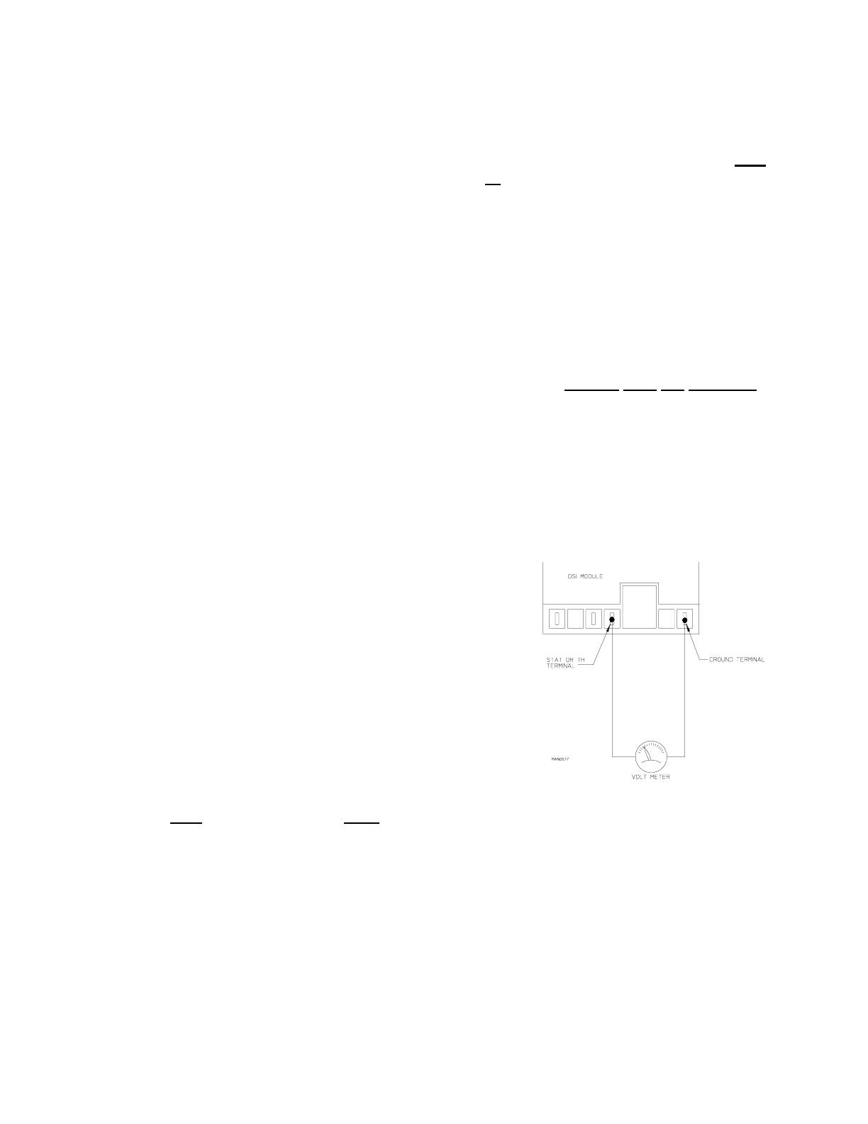
a) Check for voltage (approximately 24 VAC) across the
DSI model terminals "TH" and "GND...
If voltage (approximately 24 VAC) is evident, then, there
is a malfunction within the DSI module itself, and it must
be replaced.
If there is no voltage, and then problem is not the DSI
module or the ignition system, then the problem else-
where in the dryer (i.e., dryers' heat circuit [sail switch,
hi-limit circuits, etc.]).
2) DSI module L.E.D. indicator lights "red" for approximately 1.5 seconds (prepurge). This indicates
that
ALL the controls (including ALL the safety circuits) are functioning and power is being supplied
to the DSI module.
a) DSI module L.E.D. indicator lights "green." This indicates a normal heating cycle. This also
indicates that the preliminary diagnostics of the module has confirmed that the DSI module is
functional.
b) DSI module L.E.D. indicator lights "red" continuously... LOCK OUT MODE. This indicates
that there is a system fault and most likely the fault is internal to the DSI module. To make sure,
open and close the main door. Restart the dryer ... if the module LOCKS-OUT ("red" L.E.D.
indicator light stay on continuously) again, replace the DSI module.
  • Page 1 1
  • Page 2 2
  • Page 3 3
  • Page 4 4
  • Page 5 5
  • Page 6 6
  • Page 7 7
  • Page 8 8
  • Page 9 9
  • Page 10 10
  • Page 11 11
  • Page 12 12
  • Page 13 13
  • Page 14 14
  • Page 15 15
  • Page 16 16
  • Page 17 17
  • Page 18 18
  • Page 19 19
  • Page 20 20
  • Page 21 21
  • Page 22 22
  • Page 23 23
  • Page 24 24
  • Page 25 25
  • Page 26 26
  • Page 27 27
  • Page 28 28
  • Page 29 29
  • Page 30 30
  • Page 31 31
  • Page 32 32
  • Page 33 33
  • Page 34 34
  • Page 35 35
  • Page 36 36
  • Page 37 37
  • Page 38 38
  • Page 39 39
  • Page 40 40
  • Page 41 41
  • Page 42 42
  • Page 43 43
  • Page 44 44
  • Page 45 45
  • Page 46 46
  • Page 47 47
  • Page 48 48
  • Page 49 49
  • Page 50 50
  • Page 51 51
  • Page 52 52
  • Page 53 53
  • Page 54 54
  • Page 55 55
  • Page 56 56
  • Page 57 57
  • Page 58 58
  • Page 59 59
  • Page 60 60
  • Page 61 61
  • Page 62 62
  • Page 63 63
  • Page 64 64
  • Page 65 65
  • Page 66 66
  • Page 67 67
  • Page 68 68
  • Page 69 69
  • Page 70 70
  • Page 71 71
  • Page 72 72
  • Page 73 73
  • Page 74 74
  • Page 75 75
  • Page 76 76
  • Page 77 77
  • Page 78 78
  • Page 79 79
  • Page 80 80
  • Page 81 81
  • Page 82 82

American Dryer AD-200 User manual

Category
Electric laundry dryers
Type
User manual

Ask a question and I''ll find the answer in the document

Finding information in a document is now easier with AI