
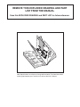
Model No. 30514.0
Serial No.
CAUTION
Read all precautions and instruc-
tions in this manual before using
this equipment. Save this manual
for future reference.
TREADMILL EXERCISER
User’s Manual
QUESTIONS?
As a manufacturer, we are com-
mitted to providing complete
customer satisfaction. If you
have questions, or if there are
missing parts, please call:
1-888-936-4266
Mon.–Fri. 8h00 until 17h00 EST
(excluding holidays).
Serial Number
Decal

TABLE OF CONTENTS
IMPORTANT PRECAUTIONS . . . . . . . . . . . . . . . . . . . . . . . . . . . . . . . . . . . . . . . . . . . . . . . . . . . . . . . . . . . . . . . .3
BEFORE YOU BEGIN . . . . . . . . . . . . . . . . . . . . . . . . . . . . . . . . . . . . . . . . . . . . . . . . . . . . . . . . . . . . . . . . . . . . . .5
ASSEMBLY . . . . . . . . . . . . . . . . . . . . . . . . . . . . . . . . . . . . . . . . . . . . . . . . . . . . . . . . . . . . . . . . . . . . . . . . . . . . . . .6
OPERATION AND ADJUSTMENT . . . . . . . . . . . . . . . . . . . . . . . . . . . . . . . . . . . . . . . . . . . . . . . . . . . . . . . . . . . .10
HOW TO FOLD AND MOVE THE TREADMILL . . . . . . . . . . . . . . . . . . . . . . . . . . . . . . . . . . . . . . . . . . . . . . . . . .22
TROUBLESHOOTING . . . . . . . . . . . . . . . . . . . . . . . . . . . . . . . . . . . . . . . . . . . . . . . . . . . . . . . . . . . . . . . . . . . . .24
CONDITIONING GUIDELINES . . . . . . . . . . . . . . . . . . . . . . . . . . . . . . . . . . . . . . . . . . . . . . . . . . . . . . . . . . . . . . .26
ORDERING REPLACEMENT PARTS . . . . . . . . . . . . . . . . . . . . . . . . . . . . . . . . . . . . . . . . . . . . . . . . . . . . . . . . .27
LIMITED WARRANTY . . . . . . . . . . . . . . . . . . . . . . . . . . . . . . . . . . . . . . . . . . . . . . . . . . . . . . . . . . . . . .Back Cover
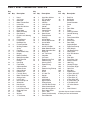
Note: An EXPLODED DRAWING and a PART LIST are attached in the center of this manual.
2

3
1. It is the responsibility of the owner to ensure
that all users of this treadmill are adequately
informed of all warnings and precautions.
2. Use the treadmill only as described.
3. Place the treadmill on a level surface, with at
least 2 m (8 ft.) of clearance behind it and 0.5 m
(2 ft.) on each side. Do not place the treadmill
on any surface that blocks air openings. To
protect the floor or carpet from damage, place a
mat under the treadmill.
4. Keep the treadmill indoors, away from mois-
ture and dust. Do not put the treadmill in a
garage or covered patio, or near water.
5. Do not operate the treadmill where aerosol
products are used or where oxygen is being
administered.
6. Keep children under the age of 12 and pets
away from the treadmill at all times.
7. The treadmill should not be used by persons
weighing more than 113 kg (250 lbs.).
8. Never allow more than one person on the
treadmill at a time.
9. Wear appropriate exercise clothes when
using the treadmill. Do not wear loose clothes
that could become caught in the treadmill.
Athletic support clothes are recommended for
both men and women.
Always wear athletic
shoes. Never use the treadmill with bare feet,
wearing only stockings, or in sandals.
10. When connecting the power cord (see page 10),
plug the power cord into a surge suppressor
(not included) and plug the surge suppressor
into a grounded circuit capable of carrying 15
or more amps. No other appliance should be on
the same circuit. Do not use an extension cord.
11. Use only a single-outlet surge suppressor that
meets all of the specifications described on
page 10.
12. Failure to use a properly functioning surge
suppressor could result in damage to the con-
trol system of the treadmill. If the control sys-
tem is damaged, the walking belt may change
speed, accelerate, or stop unexpectedly,
which may result in a fall and serious injury.
13. Keep the power cord and the surge suppres-
sor away from heated surfaces.
14. Never move the walking belt while the power
is turned off. Do not operate the treadmill if
the power cord or plug is damaged, or if the
treadmill is not working properly. (See BE-
FORE YOU BEGIN on page 5 if the treadmill is
not working properly.)
15. Never start the treadmill while you are stand-
ing on the walking belt. Always hold the
handrails while using the treadmill.
16. The treadmill is capable of high speeds.
Adjust the speed in small increments to avoid
sudden jumps in speed.
17. The pulse sensor is not a medical device.
Various factors, including your movement,
may affect the accuracy of heart rate readings.
The sensor is intended only as an exercise aid
in determining heart rate trends in general.
18. Never leave the treadmill unattended while it
is running. Always remove the key and unplug
the power cord when the treadmill is not in
use.
19. Do not attempt to raise, lower, or move the
treadmill until it is properly assembled. (See
ASSEMBLY on page 6, and HOW TO FOLD
AND MOVE THE TREADMILL on page 22.)
You must be able to safely lift 20 kg (45 lbs.) to
raise, lower, or move the treadmill.
20. When folding or moving the treadmill, make
sure that the storage latch is fully closed.
WARNING: T
o reduce the risk of burns, fire, electric shock, or injury to persons, read the
following important precautions and information before operating the treadmill.
IMPORTANT PRECAUTIONS

21. When using iFIT.com programs, an elec-
t
ronic “chirping” sound will alert you when
the speed and/or incline of the treadmill is
about to change. Always listen for the
“chirp” and be prepared. In some instances,
the speed and/or incline may change before
the personal trainer describes the change.
2
2. When using iFIT.com programs, you can man-
ually override the speed and incline settings
by pressing the speed and incline buttons.
However, when the next “chirp” is heard, the
speed and/or incline will change to the next
settings of the CD or video program.
23. Remove iFIT.com CDs and videos from your
CD player and VCR and disconnect your MP3
player when you are not using them.
24. Inspect and properly tighten all parts of the
t
readmill regularly.
2
5. Never insert any object into any opening.
2
6.
DANGER: A
lways unplug the power
cord immediately after use, before cleaning
the treadmill, and before performing the
maintenance and adjustment procedures de-
scribed in this manual. Never remove the
motor hood unless instructed to do so by an
authorized service representative. Servicing
other than the procedures in this manual
should be performed by an authorized ser-
vice representative only.
27. This treadmill is intended for in-home use
only. Do not use this treadmill in a commer-
cial, rental, or institutional setting.
WARNING: Before beginning this or any exercise program, consult your physician. This
is especially important for persons over the age of 35 or persons with pre-existing health problems.
Read all instructions before using. ICON assumes no responsibility for personal injury or property
damage sustained by or through the use of this product.
SAVE THESE INSTRUCTIONS
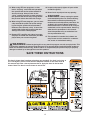
The decals shown here have been placed on your treadmill. If a decal is missing, or
if it is not legible, please call the toll-free telephone number on the front cover of
this manual and order a free replacement decal. Apply the decal in the location
shown. Note: The decals are not shown at actual size.
!
!
4

5
T
hank you for selecting the new PROFORM
®
4
00 GI
t
readmill. The PROFORM 400 GI treadmill combines
advanced technology with innovative design to help you
get the most from your exercise in the convenience of
your home. And when you’re not exercising, the PRO-
FORM 400 GI treadmill can be folded up, requiring less
than half the floor space of other treadmills.
For your benefit, read this manual carefully before
you use the treadmill. If you have questions after
r
eading this manual, please see the front cover of this
m
anual. To help us assist you, note the product model
number and serial number before calling. The model
number of the treadmill is 30514.0. The serial number
can be found on a decal attached to the treadmill (see
the front cover of this manual for the location)
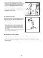
Before reading further, please review the drawing
below and familiarize yourself with the labeled parts.
BEFORE YOU BEGIN
Handrail
Upright
Storage Latch
Key/Clip
Reset/Off
Circuit Breaker
Walking Belt
Cushioned Walking Platform
for maximum exercise comfort
Foot Rail
Power Cord
RIGHT SIDE
Rear Roller
Adjustment Bolts
Console
Fan
Accessory Tray
BACK

6
ASSEMBLY
Assembly requires two persons. Set the treadmill in a cleared area and remove all packing materials. Do not
dispose of the packing materials until assembly is completed.
Note: The underside of the treadmill walking belt is coated with high-performance lubricant. During shipping, a
s
mall amount of lubricant may be transferred to the top of the walking belt or the shipping carton. This is a normal
condition and does not affect treadmill performance. If there is lubricant on top of the walking belt, simply wipe off
the lubricant with a soft cloth and a mild, non-abrasive cleaner.
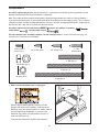
Assembly requires the included allen wrenches and your own phillips screwdriver ,
rubber mallet , and adjustable wrench .
For help identifying the assembly hardware, see the drawings below. If a part is not in the parts bag, first
check to see if it has been pre-assembled.
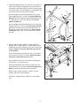
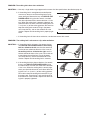
1. Make sure that the power cord is unplugged.
With the help of another person, carefully raise the
Uprights (69) to the vertical position. Insert one of the
Extension Legs (63) into the treadmill as shown. (Note: It
may be helpful to tip the Uprights as you insert the
Extension Leg.) Make sure that the Base Pad (61) is
under the Extension Leg.
Insert the other Extension Leg (63) in the same way.
!
!
1/2” Screw (119)–1
1
3/4” Screw (2)–6
Wheel Nut (32)–2
3
/4” Tek Screw (58)–8
1
2” Bolt (64)–2
Silver Ground
Screw (75)–1
1” Tek
Screw (39)–6
3” Bolt (37)–2
3
1/2” Screw (48)–6
5/16” Star
Washer (97)–2
4” Bolt (98)–2
3
69
63
61
1

7
2. Identify the Right Handrail (72), which has a large hole in
t
he left side. Feed the Upright Wire (42) into the hole in
the bottom of the Right Handrail and out of the large hole
i
n the side. Note: It may be helpful to use needlenose pli-
ers to pull the Wire Harness out of the hole.
Attach the upper end of the Right Handrail (72) to the
r
ight Upright (69) with a 3” Bolt (37).
D
o not tighten the
B
olt yet.
A
ttach the lower end of the Right Handrail with
a 4” Bolt (98) and a 5/16” Star Washer (97). Do not
tighten the Bolt yet.
Attach the upper end of the Left Handrail (71) to the left
Upright (69) with a 3” Bolt (37). Do not tighten the Bolt
yet. Attach the lower end of the Left Handrail with a 4”
Bolt (98) and a 5/16” Star Washer (97). Do not tighten
the Bolt yet.
Note: There is not a wire harness on the
left side.
42
Hole
72
97
97
98
37
3
7
71
69
69
98
Hole
2
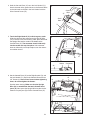
3. With the help of another person, carefully lower the
Uprights (69) as shown. Note: It may be helpful to place
one foot on one of the Extension Legs (63) as you tip the
Uprights. Make sure that the Extension Legs remain
in the Uprights.
Attach each Extension Leg (63) with two 1” Tek Screws
(39) and a Base Pad (57) as shown. Attach the lower
Tek Screw, without the Base Pad, first.
Attach two Base Pads (57) to the base of the Uprights
(69) with two 1” Tek Screws (39).
Attach the two Wheels (66) with two 2” Bolts (64) and
two Wheel Nuts (32) as shown. Do not overtighten the
Bolts; the Wheels should be able to spin freely.
With the help of another person, carefully raise the
Uprights (69) to the vertical position.
See step 2. Tighten the two 3” Bolts (37) and 4” Bolts
(98).
39
69
63
39
57
63
57
57
39
64
66
32
69
64
66
32
57
39
3

8
Small
Hole
71
4. Hold the Console Base (47) near the Left Handrail (71).
Attach the ends of the ground wires on the Console Base
t
o the indicated small hole in the Left Handrail with the
Silver Ground Screw (75).
47
75
G
round
W
ires
42
5. Touch the Right Handrail (72) to discharge any static.
Slide the sleeve off the connector on the Upright Wire
(42) as shown in the inset drawing. Next, press the end of
the Upright Wire into the socket in the bottom of the
Console Base (47).
The connector should slide easily
into the socket and snap into place. If the connector
does not slide easily and snap into place, turn the connec-
tor and then insert it.
72
47
4
5
47
6. Set the Console Base (47) on the Right Handrail (72) and
the Left Handrail (71). Attach the Console Base with four
3/4” Screws (2).
Start all four Screws before tightening
them; do not overtighten the Screws.
See the lower drawing. Make sure that the Upright
Wire (42) is routed below the two indicated round
posts (A).
Next, press the Upright Wire into the slot be-
tween the square post (B) and the Console Base (47).
2
2
72
71
6
42
Sleeve
Connector
A
B
47
42

9
9. Make sure that all parts are properly tightened before you use the treadmill. Note: Extra hardware may
be included. Keep the included allen wrenches in a secure place. The large allen wrench is used to adjust the
walking belt (see page 25). To protect the floor or carpet, place a mat under the treadmill.
8. Attach the Storage Latch (29) and the Latch Spacer (44)
to the left Upright (69) with two 3/4” Screws (2) as shown.
Do not overtighten the Screws.
2
69
29
44
48
42
G
round
Wire
36
32
47
7. Press the Upright Wire (42) into the slot in the underside
of the Console Base (47) in the indicated area. Cover the
U
pright Wire with the Right Grip Plate (36). B
e careful
not to pinch the Upright Wire. Tighten three 1/2”
S
crews (48) into the Right Grip Plate and the Console
Base.
Attach the Left Grip Plate (32) over the ground wire and
the other wires with three 1/2” Screws (48).
Be careful
not to pinch any of the wires.
48
S
lot
7
8

OPERATION AND ADJUSTMENT
T
HE PRE-LUBRICATED WALKING BELT
Your treadmill features a walking belt coated with high-
performance lubricant. IMPORTANT: Never apply sil-
icone spray or other substances to the walking
belt or the walking platform. Such substances will
deteriorate the walking belt and cause excessive
wear.
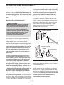
HOW TO PLUG IN THE POWER CORD
Your treadmill, like any other type of sophisticated
electronic equipment, can be seriously damaged by
sudden voltage changes in your home’s power.
Voltage surges, spikes, and noise interference can
result from weather conditions or from other appliances
being turned on or off. To decrease the possibility of
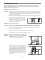
your treadmill being damaged, always use a surge
suppressor with your treadmill (see drawing 1 at
the right). To purchase a surge suppressor, see
your local Sears store or call 1-800-366-7278 and
order part number 146148, or see your local elec-
tronics store.
Use only a single-outlet surge suppressor that is
UL 1449 listed as a transient voltage surge sup-
pressor (TVSS). The surge suppressor must have a
UL suppressed voltage rating of 400 volts or less
and a minimum surge dissipation of 450 joules.
The surge suppressor must be electrically rated for
120 volts AC and 15 amps. There must be a moni
-
toring light on the surge suppressor to indicate
whether it is functioning properly. Failure to use a
properly functioning surge suppressor could result
in damage to the control system of the treadmill. If
the control system is damaged, the walking belt
may change speed, accelerate or stop unexpect-
edly, which may result in a fall and serious injury.
This product must be grounded.
If it should malfunc-
tion or break down, grounding provides a path of least
resistance for electric current to reduce the risk of elec-
tric shock. This product is equipped with a cord having
a
n equipment-grounding conductor and a grounding
plug.
Plug the power cord into a surge suppressor,
and plug the surge suppressor into an appropriate
outlet that is properly installed and grounded in
accordance with all local codes and ordinances.
Important: The treadmill is not compatible with
GFCI-equipped outlets.
This product is for use on a nominal 120-volt circuit,
and has a grounding plug that looks like the plug illus-
trated in drawing 1 below. A temporary adapter that
looks like the adapter illustrated in drawing 2 may be
used to connect the surge suppressor to a 2-pole
receptacle as shown in drawing 2 if a properly
grounded outlet is not available.
The temporary adapter should be used only until a
properly grounded outlet (drawing 1) can be installed
by a qualified electrician.
The green-colored rigid ear, lug, or the like extending
from the adapter must be connected to a permanent
ground such as a properly grounded outlet box cover.
Whenever the adapter is used it must be held in place
by a metal screw.
Some 2-pole receptacle outlet box
covers are not grounded. Contact a qualified elec
-
trician to determine if the outlet box cover is
grounded before using an adapter.
DANGER: Improper connection
of the equipment-grounding conductor can
result in an increased risk of electric shock.
Check with a qualified electrician or service-
man if you are in doubt as to whether the
product is properly grounded. Do not modify
the plug provided with the product—if it will
not fit the outlet, have a proper outlet
installed by a qualified electrician.
1
2
Grounded Outlet Box
Grounded Outlet Box
Grounding Plug
Surge Suppressor
Surge Suppressor
Grounding Pin
Adapter
Lug
Metal Screw
Grounded Outlet
Grounding Pin
10

1
1
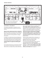
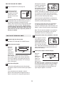
CONSOLE DIAGRAM
Note: If there is a thin sheet of plastic
on the console, remove the plastic.
Key
Clip
FEATURES OF THE CONSOLE
The treadmill console offers an impressive array of
features designed to help you get the most from your
workouts.
When the manual mode of the console is selected, the
speed and incline of the treadmill can be changed with
the touch of a button. As you exercise, the console will
display continuous exercise feedback. You can even
measure your heart rate using the built-in handgrip
pulse sensor.
In addition, the console features four preset programs.
Each program automatically controls the speed and in-
cline of the treadmill to give you an effective workout.
The console also offers two heart rate programs that
control the speed and incline of the treadmill to keep
your heart rate near a target heart rate during your
workouts.
The console also features iFIT.com interactive technol-
ogy. Having iFIT.com technology is like having a per-
sonal trainer in your home. Using a stereo audio cable,
you can connect the treadmill to your portable stereo,
home stereo, computer, or VCR and play special
iFIT.com MP3, CD, and video programs (iFIT.com MP3
programs, CDs, and videocassettes are available sepa-
rately). iFIT.com programs automatically control the
speed and incline of the treadmill as a personal trainer
guides you through every step of your workout; high-
energy music provides added motivation. To down-
load iFIT.com MP3 programs, go to www.iFIT.com.
To purchase iFIT.com CDs or videocassettes, call
the toll-free telephone number on the front cover
of this manual.
With the treadmill connected to your computer, you
can also go to www.iFIT.com and access iFIT.com
programs directly from our Web site. See
www.iFIT.com for more information.
To use the manual mode of the console
, follow the
steps beginning on page 12. To use a preset
program, see page 14. To use a heart rate program,
see page 15. To use an iFIT.com MP3, CD, or video
program, see page 19. To use an iFIT.com program
directly from our Web site, see page 21.

12
HOW TO TURN ON THE POWER
Plug in the power cord (see page 10).
Locate the reset/off
c
ircuit breaker near
the power cord. Make
s
ure that the circuit
breaker is in the reset
position.
Stand on the foot rails of the treadmill. Find the clip
attached to the key (see the drawing on page 11)
and slide the clip onto the waistband of your
clothes. Next, insert the key into the console. After
a moment, the display will light. Test the clip by
carefully taking a few steps backward until the
key is pulled from the console. If the key is not
pulled from the console, adjust the position of
the clip as needed.
HOW TO USE THE MANUAL MODE
Insert the key into the console.
See HOW TO TURN ON THE POWER above.
Select the manual mode.
When the
key is in-
serted, the
manual
mode will be
selected. If a
program has
been selected, reselect the manual mode by
pressing the Program Select button repeatedly
until a track appears in the lower part of the dis
-
play; make sure that the letters “iFIT” do not ap-
pear in the display.
Start the walking belt.
To start the walking belt, press the Start button,
the Speed + button, or one of the ten quick speed
buttons.
If the Start button or the Speed + button is
pressed, the walking belt will begin to move at 1
mph. As you exercise, change the speed of the
walking belt as desired
by pressing the Speed +
a
nd – buttons. Each
time a button is pressed,
t
he speed setting will
change by 0.1 mph; if a
button is held down, the speed setting will change
in increments of 0.5 mph. Note: After the buttons
are pressed, it may take a moment for the walking
belt to reach the selected speed setting.
If one of the quick speed buttons is pressed, the
walking belt will gradually increase in speed until it
reaches the selected speed setting.
To stop the walking belt, press the Stop button.
The time will begin to flash in the display. To
restart the walking belt, press the Start button, the
Speed + button, or one of the quick speed buttons.
Note: The first time the treadmill is used, observe
the alignment of the walking belt, and align the
walking belt if necessary (see page 26).
Change the incline of the treadmill as desired.
To change the incline of
the treadmill, press the
Incline increase and de-
crease buttons. Each
time a button is pressed,
the incline will change by
0.5%. Note: After the buttons are pressed, it may
take a moment for the treadmill to reach the se-
lected incline setting.
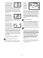
Follow your progress with the display.
When the
manual
mode or the
iFIT.com
mode is se-
lected, the
lower part of
the display will show a 1/4-mile track.
As you walk
or run, the indicators around the track will appear
in succession until the entire track appears. The
track will then disappear and the indicators will
again begin to appear in succession.
5
4
3
2
1
3
2
1
Reset
Position
Track
Track

The left side of the dis-
play will show the incline
l
evel of the treadmill, the
elapsed time, the ap-
p
roximate number of
grams of carbs you have
burned, and the distance you have walked or run.
Note: Each time the incline changes, the display
will show the incline setting for a few seconds.
When a program is selected, the display will show
the time remaining in the program instead of the
elapsed time.
The right side of the
display will show the
speed of the walking
belt, the approximate
number of calories you
have burned, and your
pace (in minutes per mile). The display will also
show your heart rate when you use the handgrip
pulse sensor.
Note: The console can
display speed and dis-
tance in either miles or
kilometers. To determine
which unit of measure-
ment is selected, hold
down the Stop button while inserting the key into
the console. An “E” for English miles or an “M” for
metric kilometers will appear in the right side of the
display. Press the Speed + button to change the
unit of measurement. When the desired unit of
measurement is selected, remove the key.
Note:
For simplicity, all instructions in this section
refer to miles.
To reset the display, press the Stop button, re-
move
the key, and then reinsert the key.
Measure your heart rate if desired.
Note: Before using the handgrip pulse sensor,
make sure that your hands are clean. If there are
sheets of
clear plastic
o
n the metal
contacts on
t
he handgrip
pulse sen-
sor, remove
the plastic.
To measure your heart rate,
stand on the foot
rails and hold the metal contacts on the handgrip
pulse sensor—
avoid moving your hands. When
your pulse is detected, the heart symbol in the right
side of the display will appear, one or two dashes
will appear, and then your heart rate will be
shown.
For the most accurate heart rate read-
ing, continue to hold the contacts for about 15
seconds.
Turn on the fan if desired.
To turn on the fan, press the fan button (the fan
button is located beside the Stop button). To turn
on the fan at high speed, press the button a sec-
ond time. To turn off the fan, press the button a
third time. Note: A few minutes after the walking
belt is stopped, the fan will automatically turn off.
When you are finished exercising, remove the
key.
Step onto the foot rails, press the Stop button, and
adjust the incline of the treadmill to the lowest
setting. The incline must be at the lowest setting
when the treadmill is folded to the storage posi-
tion or the treadmill will be damaged. Next, re-
move the key from the console and put it in a se-
cure place. Note: If the display remains lit after
the key is removed, the console is in the
“demo” mode. See page 22 and turn off the
demo mode.
When you are finished using the treadmill, switch
the reset/off circuit breaker to the off position and
unplug the power cord.
8
7
6
Contacts
13

14
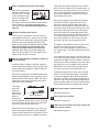
H
OW TO USE A PRESET PROGRAM
I
nsert the key fully into the console.
S
ee HOW TO TURN ON THE POWER on page
12.
S
elect one of the four preset programs.
To select
one of the
four preset
programs,
press the
Program
Select but-
ton repeat-
edly. As
each preset program is selected, the maximum
speed setting of the program and the maximum
incline setting of the program will flash in the dis
-
play for a few seconds. The display will also show
how long the program will last. The matrix in the
lower part of the display will show the first seven
speed settings of the program.
Press the Start button or the Speed + button to
start the program.
A moment after the button is pressed, the tread-
mill will automatically adjust to the first speed and
incline settings for the program. Hold the handrails
and begin walking.
Each program is divided into either 20 or 30 one-
minute segments. One speed setting and one in-
cline setting are programmed for each
segment.
Note: The same speed setting and/or incline setting
may be programmed for two or more consecutive
segments.
The speed
setting for
the first seg-
ment will be
shown in the
flashing
Current
Segment column of the matrix in the lower part of
the display. (The incline settings are not shown in
the matrix.) The speed settings for the next four
segment
s will be shown in the four columns to the
right.
When only three seconds remain in the first seg-
ment of the program, both the Current Segment
c
olumn and the column to the right will flash and a
series of tones will sound. If the speed and/or in-
c
line of the treadmill is about to change, the speed
setting and/or the incline setting will flash in the
display to alert you.
When the first segment is completed,
all speed
settings will move one column to the left
. The
speed setting for the second segment will then be
shown in the flashing Current Segment column
and the treadmill will automatically adjust to the
speed and incline settings for the second seg-
ment. Note: If all five of the indicators in the
Current Segment column are lit,
the speed settings
may move downward
so that only the highest indi-
cators appear in the matrix.
The program will continue in this way until the
speed setting for the last segment is shown in the
Current Segment column and the last segment
ends. The walking belt will then slow to a stop.
If the speed or incline setting for the current
segment is too high or too low, you can manually
override the setting by pressing the Speed or
Incline buttons. Every few times a Speed button is
pressed, an additional indicator will appear or dis-
appear in the Current Segment column; If any of
the columns to the right of the Current Segment
column have the same number of lit indicators as
the Current Segment column, an additional indica-
tor may appear or disappear in those columns as
well.
Important: When the current segment of
the program ends, the treadmill will automati-
cally adjust to the speed and incline settings
for the next segment.
To stop the program at any time, press the Stop
button. The time will begin to flash in the display.
To restart the program, press the Start button or
the Speed + button. The walking belt will begin to
move at 1 mph. When the next segment of the pro-
gram begins, the treadmill will automatically adjust
to the speed and incline settings for the next seg-
ment.
3
2
1
Current Segment

Follow your progress with the display.
See step 5 on page 12.
Measure your heart rate if desired.
S
ee step 6 on page 13.
Turn on the fan if desired.
See step 7 on page 13.
When you are finished exercising, remove the
key from the console.
When the program has ended, make sure that
the incline of the treadmill is at the lowest set-
ting. Next, remove the key from the console and
put it in a safe place.Note: If the display remains
lit after the key is removed, the console is in
the “demo” mode. See page 22 and turn off the
demo mode.
When you are finished using the treadmill, switch
the reset/off circuit breaker to the off position and
unplug the power cord.
HOW TO USE A HEART RATE PROGRAM
Insert the key into the console.
See HOW TO TURN ON THE POWER on page 12.
Select a heart rate program.
To select a
heart rate
program,
press the
Program
Select button
repeatedly.
The display
will show
which program (“P1” or “P2”) is selected. When a
heart rate program is selected, the matrix in the
lower part of the display will show the first seven
target heart rate settings of the program.
Enter your age.
When a heart rate pro-
gram is selected, the
word “AGE” will appear in
the display and the cur-
rent age setting will begin
to flash. If you have al-
ready entered your age, simply press the Start
button (the program will not start at this time). If
you have not entered your age, press the Speed +
and – buttons to enter your age, and then press
the Start button.
Enter a maximum speed setting.
After you have entered
your age, the letters
“SPd” will appear in the
display and the maximum
speed setting of the pro-
gram will begin to flash. If
desired, press the Speed + and – buttons to
change the maximum speed setting. Then, press
the Start button (the program will not start at this
time).
4
3
2
1
7
6
5
4
CAUTION: If you have heart prob-
lems, or if you are over 60 years of age and
h
ave been inactive, do not use the heart rate
programs. If you are taking medication regu-
larly, consult your physician to find whether the
medication will affect your exercise heart rate.
15

Enter a maximum target heart rate setting.
A
fter you have entered a
maximum speed setting,
t
he letters “PLS” and the
current maximum target
heart rate setting of the
program will appear in
the display. Press the Heart Rate increase and de-
crease buttons to change the maximum target
heart rate setting
(see EXERCISE INTENSITY on
page 26)
.
Hold the handgrip pulse sensor.
To use a heart rate program, you must hold the
handgrip pulse sensor. It is not necessary to hold
the pulse sensor continuously during the program;
however, you should hold the pulse sensor fre-
quently for the program to operate properly.
Each
time you hold the pulse sensor, keep your
hands on the metal contacts for at least 30
seconds.
Note: When you are not holding the
pulse sensor, the letters “PLS” will appear in the
display instead of your heart rate.
Press the Start button or the Speed + button to
start the program.
A moment after the button is pressed, the tread-
mill will automatically adjust to the first speed and
incline settings of the program. Hold the handrails
and begin walking.
Each heart rate program is divided into either 20 or
30 one-minute segments. One target heart rate is
programmed for each segment. Note: The same
target heart rate may be programmed for two or
more consecutive segments.
The target
heart rate
setting for
the first seg
-
ment will be
shown in
the flashing
Current Segment column of the matrix.
The target
heart rate settings for the
next four segments will
be shown in the columns to the right.
When only three seconds remain in the first seg-
ment of the program, both the Current Segment
column and the column to the right will flash and a
series of tones will sound. In addition, the speed
setting and the incline setting will flash in the dis-
play to alert you. When the first segment ends,
all
t
arget heart rate settings will move one column to
the left.
The target heart rate setting for the sec-
o
nd segment will then be shown in the flashing
Current Segment column.
During each segment, the console will compare
your heart rate to the target heart rate. If your
heart rate is too far below or above the target
heart rate, the speed of the walking belt will auto-
matically increase or decrease to bring your heart
rate closer to the target heart rate. If the speed
reaches the maximum speed setting of the pro-
gram (see step 4 on page 15) and your heart rate
is still too far below the target heart rate, the in-
cline of the treadmill will also increase to bring
your heart rate closer to the target heart rate.
The program will continue in this way until the tar-
get heart rate setting for the last segment is
shown in the Current Segment column and the
last segment ends. The walking belt will then slow
to a stop.
If the speed or incline setting is too high or too low
at any time during the program, you can adjust the
setting with the Speed or Incline buttons. However,
each time the console compares your heart rate to
the target heart rate, the speed and/or incline of
the treadmill may automatically change to bring
your heart rate closer to the target heart rate.
To stop the program at any time, press the Stop
button. The time will begin to flash in the display.
To restart the program, press the Start button or
the Speed + button. The walking belt will begin to
move at 1 mph. When the console compares your
heart rate to the target heart rate, the speed and/or
incline of the treadmill may automatically change.
Follow your progress with the display.
See step 5 on page 12.
Turn on the fan if desired.
See step 7 on page 13.
When you are finished exercising, remove the
key from the console.
See step 8 on page 13.
10
9
8
7
6
5
Current Segment
16

17
HOW TO CONNECT THE TREADMILL TO USE
IFIT.COM PROGRAMS
To use iFIT.com MP3 or CD programs
, the treadmill
m
ust be connected to your MP3 player, CD player,
p
ortable stereo, home stereo, or computer. See pages
17 and 18 for connecting instructions. To use iFIT.com
programs directly from our Web site, the treadmill
must be connected to your computer. See page 18 for
connecting instructions.
To use iFIT.com video pro-
grams
, the treadmill must be connected to your VCR.
See page 19 for connecting instructions.
HOW TO CONNECT YOUR MP3 PLAYER OR CD
PLAYER
A. Plug one end of the included 1/8” to 1/8” stereo
audio cable into the input jack on the console. Plug
the other end of the cable into a jack on your MP3
player or CD player. Plug your headphones into the
headphone jack on the console.
HOW TO CONNECT YOUR PORTABLE STEREO
N
ote: If your stereo has an RCA-type AUDIO OUT
jack, see instruction A below. If your stereo has a
1
/8” LINE OUT jack, see instruction B. If your
stereo has only a PHONES jack, see instruction C.
A. Plug one end of a long 1/8” to RCA stereo audio
cable (available at electronics stores) into the input
jack on the console. Plug the other end of the cable
into the AUDIO OUT jack on your stereo.
B. See the drawing above. Plug one end of a long 1/8”
to 1/8” stereo audio cable (available at electronics
stores) into the input jack on the console. Plug the
other end of the cable into the LINE OUT jack on
your stereo. Note: While the cable is plugged into
the LINE OUT jack, do not plug your headphones
into the headphone jack on the console.
C. Plug one end of a long 1/8” to 1/8” stereo audio
cable (available at electronics stores) into the input
jack on the console. Plug the other end of the cable
into the PHONES jack on your stereo. Plug your
headphones into the headphone jack on the console.
LINE OUT
PHONES
LINE OUT
PHONES
Audio
Cable
Headphones
A
A
C
PHONES
AUDIO OUT
R
IGHT
LEFT
LINE OUT
Audio Cable
A/B
A
C
PHONES
A
UDIO OUT
R
IGHT
LEFT
L
INE OUT
Audio
Cable
C
Headphones

18
HOW TO CONNECT YOUR HOME STEREO
N
ote: If your stereo has an unused LINE OUT jack,
see instruction A below. If the LINE OUT jack is
b
eing used, see instruction B.
A. Plug one end of a long 1/8” to RCA stereo audio
cable (available at electronics stores) into the input
jack on the console. Plug the other end of the cable
into the LINE OUT jack on your stereo. Note: While
the cable is plugged into the LINE OUT jack, do not
plug your headphones into the headphone jack on
the console.
B. Plug one end of a long 1/8” to RCA stereo audio
cable (available at electronics stores) into the input
jack on the console. Plug the other end of the cable
into an RCA Y-adapter (available at electronics
stores). Next, remove the wire that is currently
plugged into the LINE OUT jack on your stereo and
plug the wire into the unused side of the Y-adapter.
Plug the Y-adapter into the LINE OUT jack on your
stereo. Note: While the Y-adapter is plugged into the
LINE OUT jack, do not plug your headphones into
the headphone jack on the console.
HOW TO CONNECT YOUR COMPUTER
A
. Plug one end of a long 1/8” to 1/8” stereo audio
cable (available at electronics stores) into the input
j
ack on the console. Plug the other end of the cable
into the LINE OUT jack on your computer. Note:
While the cable is plugged into the LINE OUT jack,
do not plug your headphones into the headphone
jack on the console.
B
A
CD
VCR
Amp
LINE OUT
LINE OUT
CD
VCR
Amp
LINE OUT
Audio Cable
A
B
A
CD
VCR
Amp
LINE OUT
LINE OUT
CD
VCR
Amp
L
INE OUT
Audio
Cable
RCA
Y-adapter
Wire removed from
LINE OUT jack
B
A
LINE OUT
Audio Cable
A

19
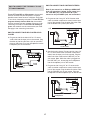
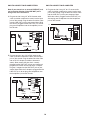
HOW TO CONNECT YOUR VCR
N
ote: If your VCR has an unused AUDIO OUT jack,
see instruction A below. If the AUDIO OUT jack is
b
eing used, see instruction B. If you have a TV
with a built-in VCR, see instruction B. If your VCR
is connected to your home stereo, see HOW TO
CONNECT YOUR HOME STEREO on page 18.
A. Plug one end of a long 1/8” to RCA stereo audio
cable (available at electronics stores) into the input
jack on the console. Plug the other end of the cable
into the AUDIO OUT jack on your VCR.
B. Plug one end of a long 1/8” to RCA stereo audio
cable (available at electronics stores) into the input
jack on the console. Plug the other end of the cable
into an RCA Y-adapter (available at electronics
stores). Next, remove the wire that is currently
plugged into the AUDIO OUT jack on your VCR and
plug the wire into the unused side of the Y-adapter.
Plug the Y-adapter into the AUDIO OUT jack on
your VCR.
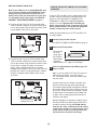
HOW TO USE AN IFIT.COM MP3, CD, OR VIDEO
PROGRAM
To use an iFIT.com MP3, CD, or video program, the
t
readmill must be connected to your MP3 player, CD
p
layer, or VCR. See HOW TO CONNECT THE
TREADMILL TO USE IFIT.COM PROGRAMS on
pages 17 to 19. To download iFIT.com MP3 pro-
grams, go to www.iFIT.com. To purchase iFIT.com
CDs or videocassettes, call the toll-free telephone
number on the front cover of this manual.
Follow the steps below to use an iFIT.com MP3, CD,
or video program.
Insert the key into the console.
See HOW TO TURN ON THE POWER on page 12.
Select the iFIT.com mode.
To select the
iFIT.com
mode, press
the Program
Select button
repeatedly
until the letters “iFIT” appear in the display.
Press the Play button on your MP3 player, CD
player, or VCR.
Note: If you are using an iFIT.com CD, insert the
CD into your CD player; if you are using an
iFIT.com videocassette, insert the videocassette
into your VCR.
A moment after the Play button is pressed, your
personal trainer will begin guiding you through
your workout. Simply follow your personal trainer’s
instructions. Note: If the time is flashing in the dis-
play, press the Start button or the Speed + button
on the console. The treadmill will not respond to
an MP3, CD, or video program while the time is
flashing in the display.
During the program, an electronic “chirping” sound
will alert you when the speed and/or incline of the
treadmill is about to change. CAUTION: Always
listen for the “chirp” and be prepared for speed
and/or incline changes. In some instances, the
speed and/or incline may change before your
personal trainer describes the change.
3
2
1
B
VIDEO AUDIO
A
NT. IN
RF OUT
IN
OUT
CH
34
A
AUDIO OUT
RIGHT
LEFT
VIDEO AUDIO
ANT. IN
R
F OUT
IN
OUT
CH
34
Audio Cable
A
B
VIDEO AUDIO
ANT. IN
RF OUT
IN
OUT
CH
34
A
AUDIO OUT
RIGHT
LEFT
VIDEO AUDIO
ANT. IN
RF OUT
IN
OUT
CH
34
B
Wire removed from
AUDIO OUT jack
RCA
Y-adapter
Audio Cable

20
If the speed or incline settings are too high or too
low, you can manually override the settings at any
t
ime by pressing the Speed or Incline buttons on
the console. However,
when the next “chirp” is
h
eard, the speed and/or incline will change to
the next settings of the program.
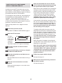
To stop the walking belt at any time, press the
Stop button on the console. The time will begin to
flash in the display. To restart the program, press
the Start button or the Speed + button. After a mo-
ment, the walking belt will begin to move at 1.0
mph. When the next “chirp” is heard, the
speed and/or incline will change to the next
settings of the program
.
When the program is completed, the walking belt
will stop. Note: To use another MP3, CD, or video
program, press the Stop button or remove the key
and go to step 1 on page 19.
Note: If the speed and/or incline of the treadmill
does not change when a “chirp” is heard:
• Make sure that the letters “iFIT” appear in the
display and that the time is not flashing in the
display. If the time is flashing, press the Start
button or the Speed + button on the console.
• Adjust the volume of your MP3 player, CD
player, or VCR. If the volume is too high or too
low, the console may not detect the program
signals.
• Make sure that the audio cable is properly
connected.
• If you are using a portable CD player and the
CD skips, set the CD player on the floor or an-
other flat surface instead of on the console.
•
See the instructions at the bottom of page 26.
Follow your progress with the display.
See step 5 on page 12.
Measure your heart rate if desired.
See step 6 on page 13.
Turn on the fan if desired.
See step 7 on page 13.
When you are finished exercising, remove the
key from the console.
See step 8 on page 13.
CAUTION: Always remove iFIT.com CDs and
videocassettes from your CD player and VCR
and disconnect your MP3 player when you are
not using them.
7
6
5
4
Page is loading ...
Page is loading ...
Page is loading ...
Page is loading ...
Page is loading ...
Page is loading ...
Page is loading ...
Page is loading ...
Page is loading ...
Page is loading ...
Page is loading ...
-
 1
1
-
 2
2
-
 3
3
-
 4
4
-
 5
5
-
 6
6
-
 7
7
-
 8
8
-
 9
9
-
 10
10
-
 11
11
-
 12
12
-
 13
13
-
 14
14
-
 15
15
-
 16
16
-
 17
17
-
 18
18
-
 19
19
-
 20
20
-
 21
21
-
 22
22
-
 23
23
-
 24
24
-
 25
25
-
 26
26
-
 27
27
-
 28
28
-
 29
29
-
 30
30
-
 31
31


Pro-Form 400 Gi Treadmill User manual
- Category
- Treadmills
- Type
- User manual
Ask a question and I''ll find the answer in the document
Finding information in a document is now easier with AI
Related papers
-
ProForm 831.294251 User manual
-
-
-
ProForm 1500 Interactive Trainer User manual
-
-
Pro-Form XP 542e User manual
-
-
-
-
Other documents
-
-
-
NordicTrack R 7200 treadmill NTL2295 M.0 User manual
-
-
-
-
-
-
-