APW Wyott AQUASNAP 30RH User manual

Category
Microwaves
Type
User manual

This manual is also suitable for

R-820BK
R-820BW
In the interest of user-safety the oven should be restored to its original
condition and only parts identical to those specified should be used.
WARNING TO SERVICE PERSONNEL: Microwave ovens con-
tain circuitry capable of producing very high voltage and
current, contact with following parts may result in a severe,
possibly fatal, electrical shock. (High Voltage Capacitor, High
Voltage Power Transformer, Magnetron, High Voltage Recti-
fier Assembly, High Voltage Harness etc..)
TABLE OF CONTENTS
Page
PRECAUTIONS TO BE OBSERVED BEFORE AND DURING SERVICING TO
AVOID POSSIBLE EXPOSURE TO EXCESSIVE MICROWAVE ENERGY...................INSIDE FRONT COVER
BEFORE SERVICING ......................................................................................................INSIDE FRONT COVER
WARNING TO SERVICE PERSONNEL................................................................................................................1
MICROWAVE MEASUREMENT PROCEDURE ...................................................................................................2
FOREWORD AND WARNING...............................................................................................................................3
PRODUCT SPECIFICATIONS ..............................................................................................................................4
GENERAL INFORMATION...................................................................................................................................4
OPERATION..........................................................................................................................................................6
TROUBLESHOOTING GUIDE ............................................................................................................................13
TEST PROCEDURE............................................................................................................................................15
TOUCH CONTROL PANEL .................................................................................................................................24
COMPONENT REPLACEMENT AND ADJUSTMENT PROCEDURE ................................................................30
PICTORIAL DIAGRAM ........................................................................................................................................37
POWER UNIT CIRCUIT ......................................................................................................................................38
CPU UNIT CIRCUIT ............................................................................................................................................39
PRINTED WIRING BOARD .................................................................................................................................40
PARTS LIST ........................................................................................................................................................41
PACKING AND ACCESSORIES .........................................................................................................................43
S5812R820BPW/
R-820BK
R-820BW
DOUBLE GRILL
CONVECTION
MICROWAVE OVEN
MODELS
SERVICE MANUAL
SHARP CORPORATION
This document has been published to be used for after
sales service only.
The contents are subject to change without notice.
CONVECTION
2
GRILL
COOK
HELP
CUSTOM
HELP
Iinteractive
COMPU
PIZZA
GRILL
BAKE
ROAST
COOK
DEFROST
CONVEC
GRILL ROAST
POPCORN
REHEAT
MINUTE
PLUS
KITCHEN
TIMER
STOP
CLEAR
START
TOUCH ON
CLOCK
POWER
LEVEL
100˚ F 150˚ F 275˚ F 300˚ F 325˚ F
350˚ F 375˚ F 400˚ F 425˚ F 450˚ F
12345
6789O
R-820BK
R-820BW
PRECAUTIONS TO BE OBSERVED BEFORE AND
DURING SERVICING TO AVOID POSSIBLE
EXPOSURE TO EXCESSIVE MICROWAVE
ENERGY
(a) Do not operate or allow the oven to be operated with the door open.
(b) Make the following safety checks on all ovens to be serviced before activating the magnetron or other
microwave source, and make repairs as necessary: (1) interlock operation, (2) proper door closing, (3)
seal and sealing surfaces (arcing, wear, and other damage), (4) damage to or loosening of hinges and
latches, (5) evidence of dropping or abuse.
(c) Before turning on microwave power for any service test or inspection within the microwave generating
compartments, check the magnetron, wave guide or transmission line, and cavity for proper alignment,
integrity, and connections.
(d) Any defective or misadjusted components in the interlock, monitor, door seal, and microwave
generation and transmission systems shall be repaired, replaced, or adjusted by procedures described
in this manual before the oven is released to the owner.
(e) A microwave leakage check to verify compliance with the Federal Performance Standard should be
performed on each oven prior to releasing oven to the owner.
BEFORE SERVICING
Before servicing an operative unit, perform a microwave emission check as per the Microwave
Measurement Procedure outlined in this service manual.
If microwave emissions level is in excess of the specified limit, contact SHARP ELECTRONICS
CORPORATION immediately @1-800-237-4277.
If the unit operates with the door open, service person should 1) tell the user not to operate the oven
and 2) contact SHARP ELECTRONICS CORPORATION and Food and Drug Administration's
Center for Devices and Radiological Health immediately.
Service personnel should inform SHARP ELECTRONICS CORPORATION of any certified unit found
with emissions in excess of 4mW/cm
2
. The owner of the unit should be instructed not to use the unit
until the oven has been brought into compliance.
1
R-820BK
R-820BW
WARNING TO SERVICE PERSONNEL
Microwave ovens contain circuitry capable of pro-
ducing very high voltage and current, contact with
following parts
may result in a severe, possibly
fatal, electrical shock.
(Example)
High Voltage Capacitor, High Voltage Power Trans-
former, Magnetron, High Voltage Rectifier Assem-
bly, High Voltage Harness etc..
Read the Service Manual carefully and follow all
instructions.
Before Servicing
1. Disconnect the power supply cord , and then
remove outer case.
2. Open the door and block it open.
3. Discharge high voltage capacitor.
WARNING:RISK OF ELECTRIC SHOCK.
DISCHARGE THE HIGH-VOLTAGE
CAPACITOR BEFORE SERVICING.
The high-voltage capacitor remains charged about 60
seconds after the oven has been switched off. Wait for 60
seconds and then short-circuit the connection of the high-
voltage capacitor (that is the connecting lead of the high-
voltage rectifier) against the chassis with the use of an
insulated screwdriver.
Whenever troubleshooting is performed the power supply
must be disconnected. It may in, some cases, be necessary
to connect the power supply after the outer case has been
removed, in this event,
1. Disconnect the power supply cord, and then remove
outer case.
2. Open the door and block it open.
3. Discharge high voltage capacitor.
4. Disconnect the leads to the primary of the power
transformer.
5. Ensure that the leads remain isolated from other
components and oven chassis by using insulation tape.
6. After that procedure, reconnect the power supply cord.
When the testing is completed,
1. Disconnect the power supply cord, and then remove
outer case.
2. Open the door and block it open.
3. Discharge high voltage capacitor.
4. Reconnect the leads to the primary of the power
transformer.
5. Reinstall the outer case (cabinet).
6. Reconnect the power supply cord after the outer case is
installed.
7. Run the oven and check all functions.
After repairing
1. Reconnect all leads removed from components during
testing.
2. Reinstall the outer case (cabinet).
3. Reconnect the power supply cord after the outer case is
installed.
4. Run the oven and check all functions.
Microwave ovens should not be run empty. To test for the
presence of microwave energy within a cavity, place a cup
of cold water on the oven turntable, close the door and set
the power to HIGH and set the microwave timer for two (2)
minutes. When the two minutes has elapsed (timer at zero)
carefully check that the water is now hot. If the water
remains cold carry out Before Servicing procedure and re-
examine the connections to the component being tested.
When all service work is completed and the oven is fully
assembled, the microwave power output should be checked
and microwave leakage test should be carried out.
Don't Touch !
Danger High Voltage
2
R-820BK
R-820BW
MICROWAVE MEASUREMENT PROCEDURE
A. Requirements:
1) Microwave leakage limit (Power density limit): The power density of microwave radiation emitted by a microwave oven
should not exceed 1mW/cm
2
at any point 5cm or more from the external surface of the oven, measured prior to acquisition
by a purchaser, and thereafter (through the useful life of the oven), 5 mW/cm
2
at any point 5cm or more from the external
surface of the oven.
2) Safety interlock switches Primary interlock relay and door sensing switch shall prevent microwave radiation emission in
excess of the requirement as above mentioned, secondary interlock switch shall prevent microwave radiation emission
in excess of 5 mW/cm
2
at any point 5cm or more from the external surface of the oven.
B. Preparation for testing:
Before beginning the actual measurement of leakage, proceed as follows:
1) Make sure that the actual instrument is operating normally as specified in its instruction booklet.
Important:
Survey instruments that comply with the requirement for instrumentation as prescribed by the performance standard
for microwave ovens, 21 CFR 1030.10(c)(3)(i), must be used for testing.
2) Place the oven tray in the oven cavity.
3) Place the load of 275±15 ml (9.8 oz) of tap water initially at 20±5˚C (68˚F) in the center of the oven cavity.
The water container shall be a low form of 600 ml (20 oz) beaker with an inside diameter of approx. 8.5 cm (3-1/2 in.)
and made of an electrically nonconductive material such as glass or plastic.
The placing of this standard load in the oven is important not only to protect the oven, but also to insure that any leakage
is measured accurately.
4) Set the cooking control on Full Power Cooking Mode
5) Close the door and select a cook cycle of several minutes. If the water begins to boil before the survey is completed,
replace it with 275 ml of cool water.
C. Leakage test:
Closed-door leakage test (microwave measurement)
1) Grasp the probe of the survey instrument and hold it perpendicular to the gap between the door and the body of the oven.
2) Move the probe slowly, not faster than 1 in./sec. (2.5 cm/sec.) along the gap, watching for the maximum indication on
the meter.
3) Check for leakage at the door screen, sheet metal seams and other accessible positions where the continuity of the metal
has been breached (eg., around the switches, indicator, and vents).
While testing for leakage around the door pull the door away from the front of the oven as far as is permitted by the closed
latch assembly.
4) Measure carefully at the point of highest leakage and make sure that the highest leakage is no greater than 4mW/cm
2
,
and that the secondary interlock switch does turn the oven OFF before any door movement.
NOTE: After servicing, record data on service invoice and microwave leakage report.
3
R-820BK
R-820BW
SHARP ELECTRONICS CORPORATION
SHARP PLAZA, MAHWAH,
NEW JERSEY 07430-2135
SERVICE MANUAL
DOUBLE GRILL
CONVECTION
MICROWAVE OVEN
R-820BK / R-820BW
FOREWORD
This Manual has been prepared to provide Sharp Electronics Corp.
Service Personnel with Operation and Service Information for the
SHARP MICROWAVE OVEN, R-820BK, R-820BW.
It is recommended that service personnel carefully study the entire
text of this manual so that they will be qualified to render satisfactory
customer service.
Check the interlock switches and the door seal carefully. Special
attention should be given to avoid electrical shock and microwave
radiation hazard.
WARNING
Never operate the oven until the following points are ensured.
(A) The door is tightly closed.
(B) The door brackets and hinges are not defective.
(C) The door packing is not damaged.
(D) The door is not deformed or warped.
(E) There is no other visible damage with the oven.
Servicing and repair work must be carried out only by trained service
personnel.
DANGER
Certain initial parts are intentionally not grounded and present
a risk of electrical shock only during servicing. Service
personnel - Do not contact the following parts while the
appliance is energized;
High Voltage Capacitor, Power Transformer, Magnetron, High
Voltage Rectifier Assembly, High Voltage Harness;
If provided, Vent Hood, Fan assembly, Cooling Fan Motor.
All the parts marked “*” on parts list are used at voltages more than
250V.
Removal of the outer wrap gives access to voltage above 250V.
All the parts marked “” on parts list may cause undue microwave
exposure, by themselves, or when they are damaged, loosened
or removed.
PRODUCT DESCRIPTION
GENERAL INFORMATION
OPERATION
TROUBLESHOOTING GUIDE AND
TEST PROCEDURE
TOUCH CONTROL PANEL
COMPONENT REPLACEMENT
AND ADJUSTMENT PROCEDURE
WIRING DIAGRAM
PARTS LIST
4
R-820BK
R-820BW
ITEM DESCRIPTION
Power Requirements 120 Volts
12.5 Amperes (Microwave) / 13.0 Amperes (Grill/ Convection)
60 Hertz / Single phase, 3 wire grounded
Power Output 900 watts (IEC 705 Test Procedure)
Operating frequency of 2450MHz
Top Heater Power Output 1000 Watts
Top & Bottom Heater Power Output 1500 Watts
Case Dimensions Width 20-1/2" Height 12-1/8" Depth 19-3/4"
Cooking Cavity Dimensions
(0.9 Cubic Feet )
Width 13-7/8" Height 7-1/2" Depth 14-1/2"
Control Complement Touch Control System
Timer (0 - 99 min. 99 seconds)
Microwave Power for Variable Cooking
Repetition Rate;
P-HI...........................................Full power throughout the cooking time
P-90 ............................................................. approx. 90% of Full Power
P-80 ............................................................. approx. 80% of Full Power
P-70 ............................................................. approx. 70% of Full Power
P-60 ............................................................. approx. 60% of Full Power
P-50 ............................................................. approx. 50% of Full Power
P-40 ............................................................. approx. 40% of Full Power
P-30 ............................................................. approx. 30% of Full Power
P-20 ............................................................. approx. 20% of Full Power
P-10 ............................................................. approx. 10% of Full Power
P-0 ............................................. No power throughout the cooking time
Grill Cooking (GRILL)........Top and Bottom Grill Mode / Top Grill Mode only
Convection Cooking (CONVEC) .......................... 100 - 450˚F Temp. control
Roast Cooking (ROAST)..........................325˚F with 30% microwave power
CUSTOM HELP pad, COMPU COOK/ BAKE/ PIZZA/ GRILL/ ROAST pads
COMPU DEFROST pad, CONVEC pad, GRILL pad, ROAST pad
POPCORN pad, REHEAT pad, MINUTE PLUS pad
Number and temperature selection pads, KITCHEN TIMER pad, CLOCK pad
STOP/CLEAR pad, POWER LEVEL pad, START / TOUCH ON pad
Oven Cavity Light Yes
Safety Standard UL Listed FCC Authorized
DHHS Rules, CFR, Title 21, Chapter 1, Subchapter J
SPECIFICATION
GENERAL INFORMATION
GROUNDING INSTRUCTIONS
This oven is equipped with a three prong grounding plug. It must be plugged into a wall receptacle that is properly installed
and grounded in accordance with the National Electrical Code and local codes and ordinances.
In the event of an electrical short circuit, grounding reduces the risk of electric shock by providing an escape wire for the
electric current.
WARNING: Improper use of the grounding plug can result in a risk of electric shock.
Electrical Requirements
The electrical requirements are a 115 -120 volt 60 Hz, AC only,
15 or 20 amp. fused electrical supply. It is recommended that a separate circuit serving only this appliance be provided. When
installing this appliance, observe all applicable codes and ordinances.
5
R-820BK
R-820BW
A short power-supply cord is provided to reduce risks of becoming
entangled in or tripping over a longer cord.
Where a two-pronged wall-receptacle is encountered, it is the personal
responsibility and obligation of the customer to contact a qualified
electrician and have it replaced with a properly grounded three-pronged
wall receptacle or have a grounding adapter properly grounded and
polarized. If the extension cord must be used, it should be a 3-wire, 15
amp. or higher rated cord. Do not drape over a countertop or table where
it can be pulled on by children or tripped over accidentally.
CAUTION: DO NOT UNDER ANY CIRCUMSTANCES CUT OR RE-
MOVE THE ROUND GROUNDING PRONG FROM THIS
PLUG.
3-Pronged Plug
Grounded
Receptacle Box
Grounding Pin
3-Pronged Receptacle
OVEN DIAGRAM
1. Oven light
2. Top heaters (Grill heaters)
3. Oven door with see through window
4. Door hinges
5. Safety door latches
6. Door seals and sealing surfaces
7. Bottom heater
8. Oven cavity
9. Turntable motor shaft
10.Ventilation openings
11.Waveguide cover
12.One touch door opening button
13.Auto-Touch control panel
14.Time display
15.Power supply cord
16.Outer cabinet
17.Menu label
NOTE:
1. Ensure that the bottom heater is in the lowest
position as shown in the figure, as it is possible to
move it up and down to help with cleaning.
2. Place the turntable support over the turntable motor
shaft on the floor of the cavity.
3. Then place the turntable onto the turntable support.
TOUCH CONTROL PANEL
Turntable Turntable
support
Rack
Turntable 
motor shaft
Bottom 
heater
COOK
HELP
CUSTOM
HELP
Iinteractive
COMPU
PIZZA GRILL
BAKE ROAST
COOK
DEFROST
CONVEC
GRILL ROAST
POPCORN
REHEAT
MINUTE
PLUS
KITCHEN
TIMER
STOP
CLEAR
START
TOUCH ON
CLOCK
POWER
LEVEL
100˚ F 150˚ F 275˚ F 300˚ F 325˚ F
350˚ F 375˚ F 400˚ F 425˚ F 450˚ F
12345
6789O
1
4
u
3
0
0
0
0
5
5
2
6
w7
9
8
q
e
r
t
y
6
R-820BK
R-820BW
OPERATION
DESCRIPTION OF OPERATING SEQUENCE
The following is a description of component functions during
oven operation.
OFF CONDITION
Closing the door activates door sensing switch and second-
ary interlock switch. (In this condition, the monitor switch
contacts are opened.)
When oven is plugged in, 120 volts A.C. is supplied to the
control unit. (Figure O-1).
1. The display will show , , ,
, , , , ,
and .
To set any program or set the clock, you must first touch
the STOP/CLEAR pad. The display will clear, and " : "
will appear.
MICROWAVE COOKING CONDITION
Program desired cooking time by touching the NUMBER
pads. Program the power level by touching the POWER
LEVEL pad and then a Number pad. When the START pad
is touched, the following operations occur:
1. The contacts of relays are closed and components
connected to the relays are turned on as follows.
(For details, refer to Figure O-2)
RELAY CONNECTED COMPONENTS
RY-2 Power transformer
RY-5 Fan motor
RY-6 Oven lamp/ Turntable motor
2. 120 volts A.C. is supplied to the primary winding of the
power transformer and is converted to about 3.1 volts
A.C. output on the filament winding, and approximately
2260 volts A.C. on the high voltage winding.
3. The filament winding voltage heats the magnetron
filament and the H.V. winding voltage is sent to a voltage
doubler circuit.
4. The microwave energy produced by the magnetron is
channelled through the waveguide into the cavity feed-
box, and then into the cavity where the food is placed to
be cooked.
5. Upon completion of the cooking time, the power
transformer, oven lamp, etc. are turned off, and the
generation of microwave energy is stopped. The oven
will revert to the OFF condition.
6. When the door is opened during a cook cycle, monitor
switch, door sensing switch, secondary interlock switch,
relay (RY5), relay (RY6) and primary interlock relay(RY2)
are activated with the following results. The circuits to the
turntable motor, the cooling fan motor, and the high
voltage components are de-energized, the oven lamp
remains on, and the digital read-out displays the time still
remaining in the cook cycle when the door was opened.
7. The monitor switch electrically monitors the operation of
the secondary interlock switch and primary interlock
relay and is mechanically associated with the door so
that it will function in the following sequence.
(1)
When the door opens from the closed position, the
relay
(RY5)
, primary interlock relay(RY2) and secondary
interlock switch open their contacts. And contacts of the
relay(RY6) remains closed. Then the monitor switch
contacts close.
(2)When the door is closed from the open position, the
monitor switch contacts open first. Then the contacts of
the secondary interlock switch and door sensing switch
close. And contacts of the relay(RY6) open.
If the secondary interlock switch and primary interlock relay
(RY2) fail with the contacts closed when the door is opened,
the closing of the monitor switch contacts will form a short
circuit through the monitor fuse, secondary interlock switch,
relay(RY6) and primary interlock relay(RY2), causing the
monitor fuse to blow.
POWER LEVEL P-0 TO P-90 COOKING
When Variable Cooking Power is programmed, the 120
volts A.C. is supplied to the power transformer intermittently
through the contacts of relay(RY-2) which is operated by the
control unit within a 32 second time base. Microwave power
operation is as follows:
VARI-MODE ON TIME OFF TIME
Power 10(P-HI) 32 sec. 0 sec.
(100% power)
Power 9(P-90) 30 sec. 2 sec.
(approx. 90% power)
Power 8(P-80) 26 sec. 6 sec.
(approx. 80% power)
Power 7(P-70) 24 sec. 8 sec.
(approx. 70% power)
Power 6(P-60) 22 sec. 10 sec.
(approx. 60% power)
Power 5(P-50) 18 sec. 14 sec.
(approx. 50% power)
Power 4(P-40) 16 sec. 16 sec.
(approx. 40% power)
Power 3(P-30) 12 sec. 20 sec.
(approx. 30% power)
Power 2(P-20) 8 sec. 24 sec.
(approx. 20% power)
Power 1(P-10) 6 sec. 26 sec.
(approx. 10% power)
Power 0(P-0) 0 sec. 32 sec.
(0% power)
Note: The ON/OFF time ratio does not correspond with
the percentage of microwave power, because
approx. 2 seconds are needed for heating of the
magnetron filament.
GRILL COOKING CONDITIONS
The oven has two grill cooking conditions. They are the TOP
HEATER mode and TOP AND BOTTOM HEATER mode.
7
R-820BK
R-820BW
TOP AND BOTTOM HEATER MODE
In this mode, the food is cooked by both the top heaters and
bottom heater. Press the GRILL pad and number "1" pad
and then enter the cooking time by pressing the number
pads. When the START pad is pressed, the following
operations occur (Figure O-3a):
1. The relays(RY3, RY4, RY5 and RY6) are energized.
2. The numbers of the digital read-out start the count down
to zero.
3. Then the top heaters, bottom heater, turntable motor,
oven lamp and fan motor are energized.
4. Now, the food is grilled by the top heaters and the bottom
heater.
5. Upon completion of the selected cooking time, audible
signal sounds and the contacts of relays(RY3, RY4 and
RY6) are opened, then the top heating elements, bottom
heating element, turntable motor and oven lamp are de-
energized. But the relay(RY5) stays closed and the fan
motor operates for 5 minutes. But if the cooking time is
less than 2 minutes the relay(RY5) will not stay closed.
NOTE: If the total grill cooking time is beyond 35 minutes,
the relay(RY1) is energized and the convection
motor is energized.
TOP HEATER MODE
In this mode, the food is cooked by the top heaters. Press the
GRILL pad and number "2" pad and then enter the cooking
time by pressing the number pads. When the START pad is
pressed, the following operations occur (Figure O-3b):
1. The relays(RY3, RY5 and RY6) are energized.
2. The numbers of the digital read-out start the count down
to zero.
3. Then the top heaters, turntable motor, oven lamp and fan
motor are energized.
4. Now, the food is grilled by the top heaters.
5. Upon completion of the selected cooking time, audible
signal sounds and the contacts of relays(RY3 and RY6)
are opened, then the top heaters, turntable motor and
oven lamp are de-energized. But the relay(RY5) stays
closed and the fan motor operates for 5 minutes. But if
the cooking time is less than 2 minutes the relay(RY5)
will not stay close.
NOTE: If the total grill cooking time is beyond 35 minutes,
the relay(RY1) is energized and the convection
motor is energized.
CONVECTION COOKING CONDITION WITH PREHEAT
Touch the CONVEC pad and select the convection with
preheat mode by touching the number "1" pad.
1. Program desired convection temperature by touching
the Temperature pad. Enter the cooking time by touching
the number pads. When the START pad is touched, the
following operations occur:
PREHEATING CONDITION
2. The coil of shut-off relays (RY5 and RY6) are energized,
the oven lamp, cooling fan motor and turntable motor are
turned on.
3. The coil of relays(RY3 and RY4) are energized by the
control unit, and the top heaters and the bottom heater
work with 100% power. The relay(RY1) and the
convection motor are not energized at this preheating
condition.
NOTE: If the cavity temperature is lower than 100˚F(38C) at
4 minutes and 15 seconds after the preheat is
started, the control unit judges that the thermistor is
opened. And the oven is stopped.
4. When the oven temperature reaches the selected preheat
temperature, the following operations occur:
4-1 The relays(RY3 and RY4) are de-energized by the
control unit temperature circuit and thermistor,
opening the circuit to the heating element.
4-2. The oven will continue to function for 30 minutes,
turning the top heaters and the bottom heater on
and off, as needed to maintain the selected preheat
temperature. The oven will shutdown completely
after 30 minutes
CONVECTION TIME COOKING CONDITION
5. When the preheat temperature is reached, a beep signal
will sound indicating that the holding temperature has
been reached in the oven cavity. Open the door and
place the food to be cooked in the oven. When the
START pad is touched, the following operations occur:
6. The numbers on the digital read-out start to count down
to zero.
7. The relays(RY1, RY5 and RY6) are energized and the
oven lamp, turntable motor, cooling fan motor and
convection motor are energized.
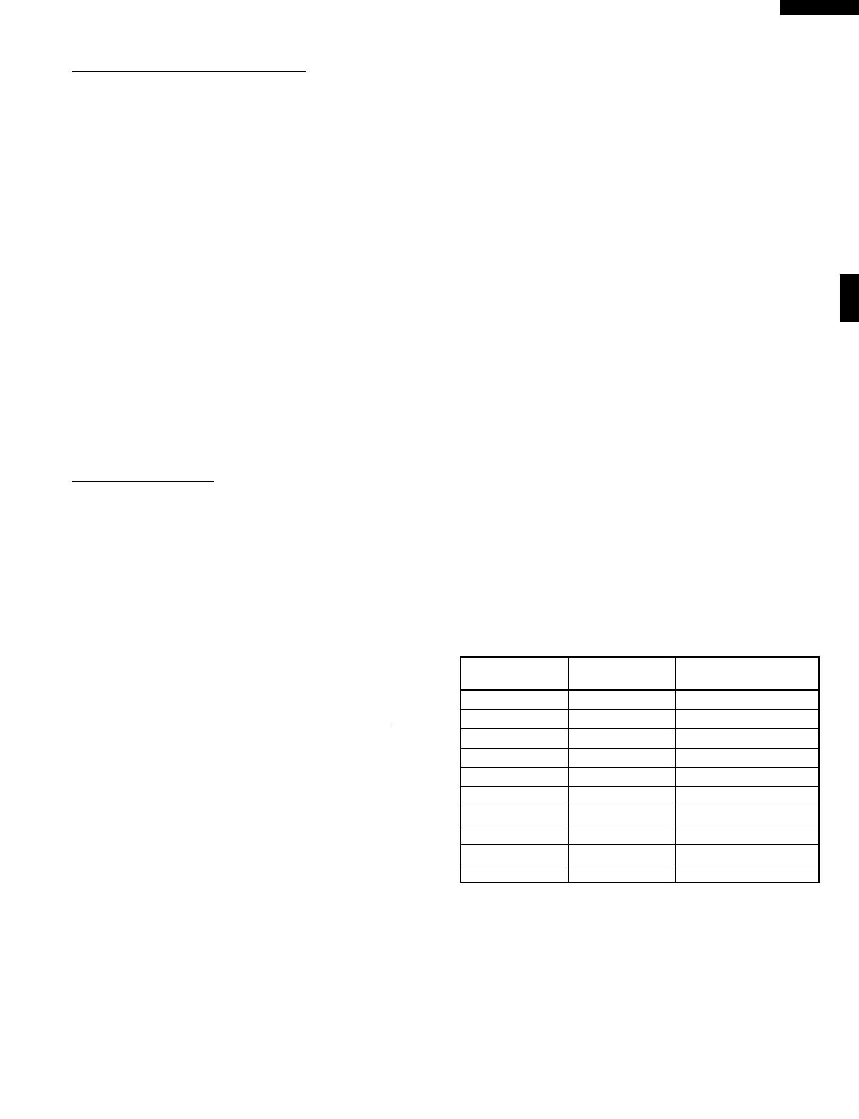
8. The relays(RY3 and RY4) are energized (if the cavity
temperature is lower than the selected temperature) and
the main supply voltage is applied to the heating element
to return to the selected cooking temperature. The top
heaters and the bottom heater work in accordance with
the following table while the heaters are energized.
Selected Temp- Top Heaters Bottom Heaters
erature (˚F) Power (%) Power (%)
100 20 10(after 3min. 0%)
150 20 10
275 40 40
300 40 50
325 50 50
350 50 60
375 60 60
400 60 70
425 70 70
450 70 80
9. Upon completion of the cooking time, the audible signal
will sound, and oven lamp, turntable motor, cooling fan
motor and convection motor are de-energized. At the
end of the convection cycle, if the cavity air temperature
is above 250˚F(120˚C), the circuit to RY5 will be
maintained (by the thermistor circuit) to continue operation
of the cooling fan motor until the temperature drops
below 220˚F(104˚C), at which time the relay will be de-
energized, turning off the fan motor. Relay RY1 will
however, open as soon as the convection cycle has
ended, turning off the convection fan motor.
8
R-820BK
R-820BW
ROAST COOKING CONDITION
Touch the ROAST pad once. And then program desired
cooking time by touching the number pads. The ROAST
pad is preprogrammed for 325˚F with 30% microwave
power.
NOTE: The microwave power can not be changed. To
change the temperature, touch the ROAST pad
twice. When the display says "SELECT TEMP",
touch desired temperature pad.
When the START pad is pressed, the following operations
occur:
1. The numbers on the digital read-out start to count down.
2. The shut-off relays(RY1, RY5 and RY6) are energized,
turning on the oven lamp, turntable motor, cooling fan
motor and convection motor.
3. The microwave relay(RY2) is energized for 16 seconds
within a 48 second time base.
4. The heater relays(RY3 and RY4) are energized
intermittently within a 48 second time base. The power
output is set in accordance with the following table.
Selected Temp- Top Heaters Bottom Heaters
erature (˚F) Power (%) Power (%)
100 20 40
150 30 50
275 50 60
300 60 70
325 70 70
350 70 70
375 70 70
400 70 70
425 70 70
450 70 70
5. The microwave relay(RY2) and the heater relays(RY3
and RY4) are not energized simultaneously.
ON/OFF TIME RATIO
In grill cooking, convection cooking or roast cooking, the top
heaters, bottom heater or magnetron operate whithin a 48
second time base. The following table is the ON / OFF time
ratio at each power output of the top heaters, bottom heater
or magnetron.
POWER OUTPUT ON TIME OFF TIME
100% 48 sec. 0 sec.
90% 44 sec. 4 sec.
80% 40 sec. 8 sec.
70% 36 sec. 12 sec.
60% 32 sec. 16 sec.
50% 26 sec. 22 sec.
40% 22 sec. 26 sec.
30% 16 sec. 32 sec.
20% 12 sec. 36 sec.
10% 8 sec. 40 sec.
FIRE SENSING FEATURE (MICROWAVE MODE)
This model incorporates a sensing feature which will stop
the oven's operation if there is a fire in the oven cavity during
microwave cooking.
This is accomplished by the LSI repeatedly measuring the
voltage across the temperature measurement circuit (ther-
mistor) during it's 32-seconds time base comparing the
obtained voltage measurements. If the most recent voltage
measured is 700mV greater than the previous voltage
measured, the LSI judges it as a fire in the oven cavity and
switches off the relays to the power transformer, fan motor,
oven lamp and turntable motor. The LSI also stops counting
down. Please refer to the following section for a more
detailed description.
Operation
Please refer to the timing diagrams below.
1. The thermistor operates within a 32-seconds time base
and it is energized for three (3) seconds and off for 29
seconds. Two (2) seconds after the thermistor is
energized, the voltage across the temperature
measurement circuit is sampled by the LSI and twenty
one (21) seconds after the thermistor is cut off the LSI
turns on the cooling fan for six (6) seconds.
2. The above procedure is repeated. If the difference
between the first voltage measured (in step 1) and the
voltage measured when the procedure is repeated (step
2) is greater than 700mV the LSI makes the judgment
that there is a fire in the oven cavity and will switch off the
relays to the power transformer, fan motor, oven lamp
and turntable motor. The LSI also stops counting down.
3. Once the fire sensor feature has shut the unit down, the
programmed cooking cycle may be resumed by pressing
the "START" pad or the unit may be reset by pressing the
"CLEAR" pad.
THERMISTOR
SENSING
VOLTAGE
ON
OFF
ON
OFF
0 2 32 64 (sec.)
3 sec.
Sensing the voltage across temperature 
measurement circuit.
9
R-820BK
R-820BW
SCHEMATIC
NOTE: CONDITION OF OVEN
1. DOOR CLOSED.
2. MICROWAVE POWER LEVEL PAD PRESSED ONCE(100%).
3. COOKING TIME PROGRAMMED.
4. START PAD TOUCHED.
Figure O-2 Oven Schematic-Microwave cooking Condition
SCHEMATIC
NOTE: CONDITION OF OVEN
1. DOOR CLOSED.
2. : OR CLOCK APPEAR ON DISPLAY.
NOTE: Indicates components with potential above 250 V.
Figure O-1 Oven Schematic-OFF Condition
FM
TTM
OVEN LAMP
FAN MOTOR
TURNTABLE 
MOTOR
H.V. RECTIFIER
CONTROL UNIT
RPIMARY
INTERLOCK RELAY
COM.
COM.
COM.
N.O.
COM.
N.O. N.O.
N.O.
A1
DOOR
SENSING
SWITCH
BRNBLU
G-Y
EARTH
LIVENEUTRAL
RY4
RY3
RY2:
RY6
RY5
CM
CONVECTION
MOTOR
THERMISTOR
RY1
CAPACITOR
0.94µF
AC2200V
GRILL HEATER (TOP)
BOTTOM HEATER
MAGNETRON
POWER 
TRANSFORMER
B2
B1
A3
A5
D1
D3
SECONDARY
INTERLOCK SWITCH
THERMAL CUT-OUT
(OVEN)
THERMAL
CUT-OUT
(MAG.)
MONITOR SWITCH
FUSE 20A
120V
~ 60Hz
OL
10
R-820BK
R-820BW
SCHEMATIC
NOTE: CONDITION OF OVEN
1. DOOR CLOSED.
2. GRILL PAD TOUCHED.
3. NUMBER "2" PAD TOUCHED.
4. COOKING TIME PROGRAMMED.
5. START PAD TOUCHED.
SCHEMATIC
NOTE: CONDITION OF OVEN
1. DOOR CLOSED.
2. GRILL PAD TOUCHED.
3. NUMBER "1" PAD TOUCHED.
4. COOKING TIME PROGRAMMED.
5. START PAD TOUCHED.
Figure O-3a Oven Schematic-Grill cooking Condition (TOP AND BOTTOM HEATER mode)
NOTE: Indicates components with potential above 250 V.
Figure O-3b Oven Schematic-Grill cooking Condition (TOP HEATER mode)
FM
TTM
OVEN LAMP
FAN MOTOR
TURNTABLE 
MOTOR
H.V. RECTIFIER
CONTROL UNIT
RPIMARY
INTERLOCK RELAY
COM.
COM.
COM.
N.O.
COM.
N.O. N.O.
N.O.
A1
DOOR
SENSING
SWITCH
BRNBLU
G-Y
EARTH
LIVENEUTRAL
RY4
RY3
RY2:
RY6
RY5
CM
CONVECTION
MOTOR
THERMISTOR
RY1
CAPACITOR
0.94µF
AC2200V
GRILL HEATER (TOP)
BOTTOM HEATER
MAGNETRON
POWER 
TRANSFORMER
B2
B1
A3
A5
D1
D3
SECONDARY
INTERLOCK SWITCH
THERMAL CUT-OUT
(OVEN)
THERMAL
CUT-OUT
(MAG.)
MONITOR SWITCH
FUSE 20A
120V
~ 60Hz
OL
11
R-820BK
R-820BW
Figure O-5 Oven Schematic-Roast cooking Condition
Figure O-4 Oven Schematic-Convection cooking Condition (Convection with preheat mode)
SCHEMATIC
NOTE: CONDITION OF OVEN
1. DOOR CLOSED.
2. CONVECTION PAD TOUCHED.
3. NUMBER "1" PAD TOUCHED.
4. TEMPERATURE PAD TOUCHED.
5. COOKING TIME PROGRAMMED.
6. START PAD TOUCHED.
SCHEMATIC
NOTE: CONDITION OF OVEN
1. DOOR CLOSED.
2. ROAST PAD TOUCHED.
3. COOKING TIME PROGRAMMED.
4. START PAD TOUCHED.
FM
TTM
OVEN LAMP
FAN MOTOR
TURNTABLE 
MOTOR
H.V. RECTIFIER
CONTROL UNIT
RPIMARY
INTERLOCK RELAY
COM.
COM.
COM.
N.O.
COM.
N.O. N.O.
N.O.
A1
DOOR
SENSING
SWITCH
BRNBLU
G-Y
EARTH
LIVENEUTRAL
RY4
RY3
RY2:
RY6
RY5
CM
CONVECTION
MOTOR
THERMISTOR
RY1
CAPACITOR
0.94µF
AC2200V
GRILL HEATER (TOP)
BOTTOM HEATER
MAGNETRON
POWER 
TRANSFORMER
B2
B1
A3
A5
D1
D3
SECONDARY
INTERLOCK SWITCH
THERMAL CUT-OUT
(OVEN)
THERMAL
CUT-OUT
(MAG.)
MONITOR SWITCH
FUSE 20A
120V
~ 60Hz
OL
NOTE: The microwave relay (RY2) and the heater relay (RY3 or RY4) are not energized
simultaneously.
12
R-820BK
R-820BW
DESCRIPTION AND FUNCTION OF COMPONENTS
DOOR OPEN MECHANISM
The door is opened by pushing the open button on the
control panel, refer to Figure D-1.
When the open button is pushed, the open button pushes up
the switch lever, and then the switch lever pushes up the
latch head. The latch heads are moved upward and re-
leased from latch hook. Now the door will open.
of the monitor switch contacts.
CAUTION: BEFORE REPLACING A BLOWN MONITOR
FUSE TEST THE DOOR SENSING SWITCH,
PRIMARY INTERLOCK RELAY (RY2), RELAY
(RY6), SECONDARY INTERLOCK SWITCH
AND MONITOR SWITCH FOR PROPER OP-
ERATION. (REFER TO CHAPTER "TEST PRO-
CEDURE").
NOTE: MONITOR FUSE AND MONITOR SWITCH ARE
REPLACED AS AN ASSEMBLY.
TURNTABLE MOTOR
The turntable motor rotates the turntable located on the
bottom of the oven cavity, so that the food on the turntable
cook evenly during cooking. The turntable may turn in either
direction.
COOLING FAN MOTOR
The cooling fan motor drives a blade which draws external
cool air. This cool air is directed through the air vanes
surrounding the magnetron and cools the magnetron. This
air is channelled through the oven cavity to remove steam
and vapors given off from the heating food. It is then
exhausted through the exhausting air vents at the oven
cavity.
MONITOR FUSE
1. The monitor fuse blows when the contacts (COM-NO) of
the primary interlock relay (RY2) and secondary interlock
switch remain closed with the oven door open and when
the monitor switch closes.
2. If the wire harness or electrical components are short-
circuited, this monitor fuse blows to prevent an electric
shock or fire hazard.
THERMAL CUT-OUT 125˚C (MAGNETRON)
This thermal cut-out protects the magnetron against over-
heating. If the temperature goes up higher than 257˚F
(125˚C) because the fan motor is interrupted or the ventila-
tion openings are blocked, the thermal cut-out will open and
line voltages to the high voltage transformer will be cut off
and the operation of the magnetron will be stopped. The
thermal cut-out will not resume.
THERMAL CUT-OUT 170˚C (OVEN)
The thermal cut-out located on the top of the oven cavity is
designed to prevent damage to the oven if the food in the
oven catch fire due to over heating produced by improper
setting of the cooking time or failure of control unit. Under the
normal operation, the oven thermal cut-out remains closed.
However, when abnormally high temperatures are reached
within the oven cavity, the oven thermal cut-out will open at
338˚F(170˚C) causing the oven to shut down. The thermal
cut-out will close in at 311˚F(155˚C).
TOP HEATERS
The top heaters are located on the top of the oven cavity
assembly. The top heaters send out heat to grill foods.
Figure D-1. Door Open Mechanism
DOOR SENSING AND SECONDARY INTERLOCK
SWITCHES
The secondary interlock switch is mounted in the lower
position of the latch hook and the door sensing switch in the
primary interlock system is mounted in the upper position of
the latch hook. They are activated by the latch heads on the
door. When the door is opened, the switches interrupt the
power to all high voltage components. A cook cycle cannot
take place until the door is firmly closed thereby activating
both interlock switches. The primary interlock system con-
sists of the door sensing switch and primary interlock relay
located on the control circuit board.
MONITOR SWITCH
The monitor switch is activated (the contacts opened) by the
latch head on the door while the door is closed. The switch
is intended to render the oven inoperative, by means of
blowing the monitor fuse, when the contacts of the primary
interlock relay (RY2) and secondary interlock switch fail to
open when the door is opened.
Functions:
1. When the door is opened, the monitor switch contacts
close (to the ON condition) due to their being normally
closed. At this time the primary interlock relay (RY2) and
secondary interlock switch are in the OFF condition
(contacts open) due to their being normally open contact
switches.
2. As the door goes to a closed position, the monitor switch
contacts are first opened and then the door sensing
switch and the secondary interlock switch contacts close.
(On opening the door, each of these switches operate
inversely.)
3. If the door is opened, and the primary interlock relay
(RY2) and secondary interlock switch contacts fail to
open, the monitor fuse blows simultaneously with closing
Latch Hook
Door
Sensing 
Switch
Monitor
Switch
Secondary
Interlock
Switch
Switch
Lever
Latch
Heads
Door
13
R-820BK
R-820BW
TROUBLESHOOTING GUIDE
Never touch any part in the circuit with your hand or an uninsulated tool while the power supply is connected.
When troubleshooting the microwave oven, it is helpful to follow the Sequence of Operation in performing the checks. Many
of the possible causes of trouble will require that a specific test be performed. These tests are given a procedure letter which
will be found in the "Test Procedure "section.
IMPORTANT: If the oven becomes inoperative because of a blown monitor fuse, check the monitor switch, relay (RY6),
primary interlock relay (RY2), door sensing switch and secondary interlock switch before replacing the
monitor fuse. If monitor fuse is replaced, the monitor switch must also be replaced. Use part FFS-
BA021WRK0 as an assembly.
IMPORTANT: Whenever troubleshooting is performed with the power supply cord disconnected. It may in, some cases,
be necessary to connect the power supply cord after the outer case has been removed, in this event,
1. Disconnect the power supply cord, and then remove outer case.
2. Open the door and block it open.
3. Discharge high voltage capacitor.
4. Disconnect the leads to the primary of the power transformer.
5. Ensure that the leads remain isolated from other components and oven chassis by using insulation tape.
6. After that procedure, reconnect the power supply cord.
When the testing is completed
1. Disconnect the power supply cord, and then remove outer case.
2. Open the door and block it open.
3. Discharge high voltage capacitor.
4. Reconnect the leads to the primary of the power transformer.
5. Reinstall the outer case (cabinet).
6. Reconnect the power supply cord after the outer case is installed.
7. Run the oven and check all functions.
BOTTOM HEATER
The bottom heater is located on the floor of the oven cavity
assembly. The bottom heater sends out heat to grill foods.
CONVECTION COOKING SYSTEM
This oven is designed with a hot air heating system where
food is not directly heated by the top heaters and the bottom
heater, but is heated by forced circulation of the hot air
produced by the top heaters and the bottom heater.
The air heated by the top heaters and the bottom heater is
circulated through the convection passage provided on the
outer casing of the oven cavity by means of the convection
fan which is driven by the convection motor. It then enters
the inside of the oven through the vent holes provided on the
left side of the oven. Next, the hot air heats the food on the
turntable and leaves the oven cavity through the vent in the
center of the oven cavity rear wall.
Most of this hot air is reheated by the top heaters and the
bottom heater and passes through the convection passage
and enters the inside of the oven cavity again, in a continu-
ing cycle.
In this way, the hot air circulates inside the oven cavity to
raise its temperature and, at the same time, comes into
contact with the food being cooked.
When the temperature inside the oven cavity reaches the
selected temperature, the top heaters and the bottom heater
are de-energized. When the temperature inside the oven
cavity drops below the selected temperature, the top heat-
ers and the bottom heater are energized again. In this way,
the inside of the oven cavity is maintained at approximately
the selected temperature.
When the convection time reaches 0, the top heaters and
the bottom heater are de-energized and the convection fan
stops operating and the oven shuts off.
14
R-820BK
R-820BW
CK = Check / RE = Replace
ABCDEEFFGH I I JLMNNNNNNOP
RERERERERE
CK CK CK
TEST PROCEDURE
MAGNETRON
POWER TRANSFORMER
H.V. RECTIFIER ASSEMBLY
HIGH VOLTAGE CAPACITOR
THERMAL CUT-OUT 170˚C
THERMAL CUT-OUT 125˚C
SECONDARY INTERLOCK SWITCH
PRIMARY INTERLOCK SYSTEM
MONITOR SWITCH
MONITOR FUSE
TOP HEATERS
BOTTOM HEATER
THERMISTOR
TOUCH CONTROL PANEL
KEY UNIT
RELAY RY1
RELAY RY2
RELAY RY3
RELAY RY4
RELAY RY5
RELAY RY6
COMPU DEFROST
FOIL PATTURN ON P.W.B.
FAN MOTOR
CONVECTION MOTOR
TURNTABLE MOTOR
POWER SUPPLY CORD
OVEN LAMP OR SOCKET
SHORTED WIRE HARNESS
OPENED WIRE HARNESS
MIS-ADJUSTMENT OF SWITCHES
CONDITION PROBLEM
POSSIBLE CASE
AND 
DEFECTIVE PARTS
Monitor fuse blows when power
cord is plugged into wall outlet.
Monitor fuse blows when the door
is opened.
Oven lamp does not light when
door is opened. (Display operates.)
Home fuse blows when power cord
is plugged into wall outlet.
"SHARP SIMPLY ..... PRESS CLOCK"
does not appear in display when
power cord is plugged into wall outlet.
Display does not operate properly
when STOP/CLEAR pad is pressed.
Oven does not start when the
START pad is pressed. (Display
operates.)
Oven lamp does not light. (Turntable
motor operates.)
Fan motor does not operate. (Oven
lamp lights.)
Turntable motor does not operate.
(Oven lamp lights.)
Oven or electrical parts does not
stop when cooking time is 0 or
STOP/CLEAR pad is pressed. 
Oven goes into cook cycle but shuts
down before end of cooking cycle.
Oven seems to be operating but little
or no heat is produced in oven load.
Oven does not operate properly
during variable cooking condition
except 100% cooking condition.
Function of COMPU DEFROST does
not operate properly.
Top heaters do not operate.
Bottom heater does not operate.
Oven seems to be operating but
little or no heat is produced in oven
load. (Microwave power does not
seem to be generated properly.)
Top heaters do not operate.
Bottom heater does not operate.
Temperature is lower or higher than
preset.
Convection motor does not operate.
Oven stops after 4 minutes 15 sec..
OFF
CONDITION
COOKING
CONDITION
(COMMON MODE)
MICROWAVE 
COOKING
CONDITION
GRILL
COOKING
CONDITION
ROAST
COOKING
CONDITION
CONVECTION
COOKING
CONDITION
15
R-820BK
R-820BW
B POWER TRANSFORMER TEST
1. Disconnect the power supply cord, and then remove outer case.
2. Open the door and block it open.
3. Discharge high voltage capacitor.
4. Disconnect the primary input terminals and measure the resistance of the transformer with an
ohmmeter. Check for continuity of the coils with an ohmmeter. On the R x 1 scale, the resistance of
the primary coil should be less than 1 ohm and the resistance of the high voltage coil should be
approximately 73 ohms; the resistance of the filament coil should be less than 1 ohm.
5. Reconnect all leads removed from components during testing.
6. Reinstall the outer case (cabinet).
7. Reconnect the power supply cord after the outer case is installed.
8. Run the oven and check all functions.
A MAGNETRON ASSEMBLY TEST
TEST PROCEDURES
PROCEDURE
LETTER
COMPONENT TEST
1. Disconnect the power supply cord, and then remove outer case.
2. Open the door and block it open.
3. Discharge high voltage capacitor.
4. To test for an open filament, isolate the magnetron from the high voltage circuit. A continuity check
across the magnetron filament leads should indicate less than 1 ohm.
5. To test for a shorted magnetron, connect the ohmmeter leads between the magnetron filament leads
and chassis ground. This test should indicate an infinite resistance. If there is little or no resistance
the magnetron is grounded and must be replaced.
6. Reconnect all leads removed from components during testing.
7. Reinstall the outer case (cabinet).
8. Reconnect the power supply cord after the outer case is installed.
9. Run the oven and check all functions.
MICROWAVE OUTPUT POWER
The following test procedure should be carried out with the microwave oven in a fully assembled
condition (outer case fitted).
HIGH VOLTAGES ARE PRESENT DURING THE COOK CYCLE, SO EXTREME CAUTION SHOULD
BE OBSERVED.
Power output of the magnetron can be measured by performing a water temperature rise test. This test
should only be used if above tests do not indicate a faulty magnetron and there is no defect in the following
components or wiring: silicon rectifier, high voltage capacitor and power transformer. This test will require
a 16 ounce (453cc) measuring cup and an accurate mercury thermometer or thermocouple type
temperature tester. For accurate results, the following procedure must be followed carefully:
1. Fill the measuring cup with 16 oz. (453cc) of tap water and measure the temperature of the water with
a thermometer or thermocouple temperature tester. Stir the thermometer or thermocouple through
the water until the temperature stabilizes. Record the temperature of the water.
2. Place the cup of water in the oven. Operate oven at POWER 10(HIGH) selecting more than 60
seconds cook time. Allow the water to heat for 60 seconds, measuring with a stop watch, second hand
of a watch or the digital read-out countdown.
3. Remove the cup from the oven and again measure the temperature, making sure to stir the
thermometer or thermocouple through the water until the maximum temperature is recorded.
4. Subtract the cold water temperature from the hot water temperature. The normal result should be 22
to 43˚F(12.2 to 23.9˚C) rise in temperature. If the water temperatures are accurately measured and
tested for the required time period the test results will indicate if the magnetron tube has low power
output (low rise in water temperature) which would extend cooking time or high power output (high
rise in water temperature) which would reduce cooking time. Because cooking time can be adjusted
to compensate for power output, the magnetron tube assembly should be replaced only if the water
temperature rise test indicates a power output well beyond the normal limits. The test is only accurate
if the power supply line voltage is 120 volts and the oven cavity is clean.
16
R-820BK
R-820BW
TEST PROCEDURES
PROCEDURE
LETTER
COMPONENT TEST
1. Disconnect the power supply cord, and then remove outer case.
2. Open the door and block it open.
3. Discharge high voltage capacitor.
4. If the capacitor is open, no high voltage will be available to the magnetron. Disconnect input leads
and check for a short or open between the terminals using an ohmmeter.
Checking with a high ohm scale, if the high voltage capacitor is normal, the meter will indicate
continuity for a short time and should indicate an open circuit once the capacitor is charged. If the
above is not the case, check the capacitor with an ohmmeter to see if it is shorted between either of
the terminals and case. If it is shorted, replace the capacitor.
5. Reconnect all leads removed from components during testing.
6. Reinstall the outer case (cabinet).
7. Reconnect the power supply cord after the outer case is installed.
8. Run the oven and check all functions.
D HIGH VOLTAGE CAPACITOR TEST
E THERMAL CUT-OUT TEST 170˚C (OVEN)
1. Disconnect the power supply cord, and then remove outer case.
2. Open the door and block it open.
3. Discharge high voltage capacitor.
4. A continuity check across the thermal cut-out terminals should indicate a closed circuit unless the
temperature of the thermal cut-out reaches approximately 338˚F(170˚C). The thermal cut-out resets
automatically below approximately 311˚F(155˚C).
An open thermal cut-out indicates overheating of the oven, check inside of oven cavity for improper
setting of cooking time or operation of control unit. Check for restricted air flow through the vent holes
of the oven cavity, especially the cooling fan and air guide.
5. Reconnect all leads removed from components during testing.
6. Reinstall the outer case (cabinet).
7. Reconnect the power supply cord after the outer case is installed.
8. Run the oven and check all functions.
THERMAL CUT-OUT TEST 125˚C (MAGNETRON)
1. Disconnect the power supply cord, and then remove outer case.
2. Open the door and block it open.
3. Discharge high voltage capacitor.
4. A continuity check across the thermal cut-out terminals should indicate a closed circuit. If the
temperature of the magnetron reaches approximately 257˚F(125˚C), the thermal cut-out opens. An
open thermal cut-out indicates overheating of the magnetron, exchange the thermal cut-out. Check
for restricted air flow to the magnetron, especially the cooling fan air guide.
C HIGH VOLTAGE RECTIFIER TEST
1. Disconnect the power supply cord, and then remove outer case.
2. Open the door and block it open.
3. Discharge high voltage capacitor.
4. Isolate the rectifier from the circuit. Using the highest ohm scale of the meter, read the resistance
across the terminals and observe, reverse the leads to the rectifier terminals and observe meter
reading. If a short is indicated in both directions, or if an infinite resistance is read in both directions,
the rectifier is probably defective and should be replaced.
5. Reconnect all leads removed from components during testing.
6. Reinstall the outer case (cabinet).
7. Reconnect the power supply cord after the outer case is installed.
8. Run the oven and check all functions.
NOTE: Be sure to use an ohmmeter that will supply a forward bias voltage of more than 6.3 volts.
(HIGH VOLTAGES ARE PRESENT AT THE HIGH VOLTAGE TERMINAL, SO DO NOT ATTEMPT TO
MEASURE THE FILAMENT AND HIGH VOLTAGE.)
17
R-820BK
R-820BW
TEST PROCEDURES
PROCEDURE
LETTER
COMPONENT TEST
1. Disconnect the power supply cord, and then remove outer case.
2. Open the door and block it open.
3. Discharge high voltage capacitor.
4. Before performing this test, make sure that the secondary interlock switch and the primary interlock
relay are operating properly, according to the above Switch Test Procedure. Disconnect the wire lead
from the monitor switch (COM) terminal. Check the monitor switch operation by using the ohmmeter
as follows. When the door is open, the meter should indicate a closed circuit. When the monitor switch
actuator is pushed by a screw driver through the lower latch hole on the front plate of the oven cavity
5. Reconnect all leads removed from components during testing.
6. Reinstall the outer case (cabinet).
7. Reconnect the power supply cord after the outer case is installed.
8. Run the oven and check all functions.
CAUTION: IF THE THERMAL CUT-OUT INDICATES AN OPEN CIRCUIT AT ROOM TEMPERATURE,
REPLACE THERMAL CUT-OUT.
1. Disconnect the power supply cord, and then remove outer case.
2. Open the door and block it open.
3. Discharge high voltage capacitor.
4. Isolate the switch and connect the ohmmeter to the common (COM.) and normally open (NO) terminal
of the switch. The meter should indicate an open circuit with the door open and a closed circuit with
the door closed. If improper operation is indicated, replace the secondary interlock switch.
5. Reconnect all leads removed from components during testing.
6. Reinstall the outer case (cabinet).
7. Reconnect the power supply cord after the outer case is installed.
8. Run the oven and check all functions.
PRIMARY INTERLOCK SYSTEM TEST
DOOR SENSING SWITCH
1. Disconnect the power supply cord, and then remove outer case.
2. Open the door and block it open.
3. Discharge high voltage capacitor.
4. Isolate the switch and connect the ohmmeter to the common (COM.) and normally open (NO) terminal
of the switch. The meter should indicate an open circuit with the door open and a closed circuit with
the door closed. If improper operation is indicated, replace the door sensing switch.
5. Reconnect all leads removed from components during testing.
6. Reinstall the outer case (cabinet).
7. Reconnect the power supply cord after the outer case is installed.
8. Run the oven and check all functions.
NOTE: If the door sensing switch contacts fail in the open position and the door is closed, the cooling
fan, turntable and oven light will be activated by relay(RY6).
PRIMARY INTERLOCK RELAY (RY2)
1. Disconnect the power supply cord, and then remove outer case.
2. Open the door and block it open.
3. Discharge high voltage capacitor.
4. Disconnect two (2) wire leads from the male tab terminals of the Primary Interlock Relay. Check the
state of the relay contacts using a ohmmeter. The relay contacts should be open. If the relay contacts
are closed, replace the circuit board entirely or the relay itself.
5. Reconnect all leads removed from components during testing.
6. Reinstall the outer case (cabinet).
7. Reconnect the power supply cord after the outer case is installed.
8. Run the oven and check all functions.
F SECONDARY INTERLOCK SWITCH TEST
G MONITOR SWITCH TEST
18
R-820BK
R-820BW
H BLOWN MONITOR FUSE TEST
TEST PROCEDURES
PROCEDURE
LETTER
COMPONENT TEST
1. Disconnect the power supply cord, and then remove outer case.
2. Open the door and block it open.
3. Discharge high voltage capacitor.
4. If the monitor fuse is blown when the door is opened, check the primary interlock relay, secondary
interlock switch and monitor switch according to the "TEST PROCEDURE" for those switches before
replacing the blown monitor fuse.
CAUTION: BEFORE REPLACING A BLOWN MONITOR FUSE, TEST THE PRIMARY INTERLOCK
RELAY, SECONDARY INTERLOCK SWITCH, DOOR SENSING SWITCH AND MONITOR
SWITCH FOR PROPER OPERATION.
If the monitor fuse is blown by improper switch operation, the monitor fuse and monitor switch must
be replaced with "monitor fuse and monitor switch assembly" part number FFS-BA021WRK0, even
if the monitor switch operates normally. The monitor fuse and monitor switch assembly is comprised
of a 20 ampere fuse and switch.
5. Reconnect all leads removed from components during testing.
6. Reinstall the outer case (cabinet).
7. Reconnect the power supply cord after the outer case is installed.
8. Run the oven and check all functions.
with the door opened (in this condition the plunger of the monitor switch is pushed in), the meter should
indicate an open circuit. If improper operation is indicated, the switch may be defective. After testing
the monitor switch, reconnect the wire lead to the monitor switch (COM) terminal and check the
continuity of the monitor circuit.
5. Reconnect all leads removed from components
during testing.
6. Reinstall the outer case (cabinet).
7. Reconnect the power supply cord after the
outer case is installed.
8. Run the oven and check all functions.
SCREW 
DRIVER
RED
WHT
MONITOR 
SWITCH
OHMMETER
I TOP HEATERS AND BOTTOM HEATER TEST
1. Disconnect the power supply cord, and then remove outer case.
2. Open the door and block it open.
3. Discharge high voltage capacitor.
4. Make sure the heater is cooled completely.
5. Resistance of heater.
Disconnect the wire leads to the heater to be tested. Using ohmmeter with low resistance range.
Check the resistance across the terminals of the heater as described in the following table.
Table: Resistance of heater
Parts name Resistance
Top heaters Approximately 7.2 x 2 = 14.4
Bottom heater Approximately 28.8
6. Insulation resistance.
Disconnect the wire leads to the heater to be tested. Check the insulation resistance between the
heater terminal and cavity using a 500V - 100M insulation tester. The insulation resistance should
be more than 10 M in the cold start.
7. If the results of above test 5 and/or 6 are out of above specifications, the heater is probably faulty and
should be replaced.
8. Reconnect all leads removed from components during testing.
9. Reinstall the outer case (cabinet).
  • Page 1 1
  • Page 2 2
  • Page 3 3
  • Page 4 4
  • Page 5 5
  • Page 6 6
  • Page 7 7
  • Page 8 8
  • Page 9 9
  • Page 10 10
  • Page 11 11
  • Page 12 12
  • Page 13 13
  • Page 14 14
  • Page 15 15
  • Page 16 16
  • Page 17 17
  • Page 18 18
  • Page 19 19
  • Page 20 20
  • Page 21 21
  • Page 22 22
  • Page 23 23
  • Page 24 24
  • Page 25 25
  • Page 26 26
  • Page 27 27
  • Page 28 28
  • Page 29 29
  • Page 30 30
  • Page 31 31
  • Page 32 32
  • Page 33 33
  • Page 34 34
  • Page 35 35
  • Page 36 36
  • Page 37 37
  • Page 38 38
  • Page 39 39
  • Page 40 40
  • Page 41 41
  • Page 42 42
  • Page 43 43
  • Page 44 44
  • Page 45 45
  • Page 46 46
  • Page 47 47
  • Page 48 48

APW Wyott AQUASNAP 30RH User manual

Category
Microwaves
Type
User manual
This manual is also suitable for

Ask a question and I''ll find the answer in the document

Finding information in a document is now easier with AI