Vivotek FD8134 Dome Owner's manual

Category
Security cameras
Type
Owner's manual

This manual is also suitable for

Quick Installation Guide
English
繁中 日本語
Español Português
簡中
Français
Deutsch
Italiano
Türkçe
Polski
Русский
Česky Svenska
VIVOTEK INC.
6F, No.192, Lien-Cheng Rd., Chung-Ho, New Taipei City, 235, Taiwan, R.O.C.
|T: +886-2-82455282| F: +886-2-82455532| E: [email protected]
VIVOTEK USA, INC.
2050 Ringwood Avenue, San Jose, CA 95131
|T: 408-773-8686| F: 408-773-8298| E: [email protected]
1MP MicroSD/SDHC Compact Design
All specications are subject to change without notice.
Copyright 2012 VIVOTEK INC. All rights reserved.
c
P/N:625011001G Rev. 1.1
FD8133/8134
Fixed Dome
Network Camera
EN - 1
English
Power off the Network Camera as
soon as smoke or unusual odors are
detected.
Contact your distributor in the event of
occurrence.
Keep the Network Camera away
from water. If the Network Camera
becomes wet, power off immediately.
Do not place the Network Camera
around heat sources, such as a
television or oven.
Refer to your user's manual for the
operating temperature.
Keep the Network Camera away from
direct sunlight.
Do not place the Network Camera in
high humidity environments.
Contact your distributor in the event of
occurrence.
Warning Before Installation
EN - 2
Do not place the Network Camera on
unsteady surfaces.
Do not touch the Network Camera
during a lightning storm.
Do not disassemble the Network
Camera.
Do not drop the Network Camera.
Do not insert sharp or tiny objects
into the Network Camera.
EN - 3
English
Software CD
FD8133 or FD8134
Alignment Sticker
Drill hole
Drill hole
Cable hole
RJ45 Female/Female Coupler /
Screws / Clamp Core
Power Adapter
5
0
0
0
2
4
7
0
1
G
Package Contents
1
Quick Installation Guide /
Warranty Card
EN - 4
First, follow the instructions below to remove the dome cover.
Hardware Installation
3
Physical Description
2
Dome Cover
Lens
IR LEDs (8 units, distance 10m)
(FD8134 only)
Reset Button
General I/O Terminal Block
Status LED
Light Sensor
MicroSD/SDHC
Card Slot
Black Cover
Ethernet 10/100
RJ45 Plug
Power Cord Socket
Record the MAC address before
installing the camera.
Network Camera
Model No: FD8134
Made in Taiwan
This device complies with part 15 of the FCC rules. Operation is subject to the following two conditions:
(1)This device may not cause harmful interference, and
(2) this device must accept any interference received, including interference that may cause undesired operation.
Pat. 6,930,709
RoHS
V I
MAC:0002D107258A
EN - 5
English
A
A
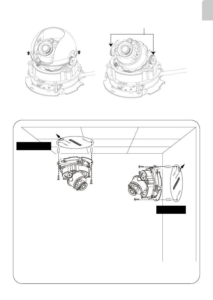
1. Attach the alignment sticker to the ceilling/wall.
2. Through the two circles on the sticker, drill two pilot holes into the
ceilling/wall.
3. The Network Camera can be mounted with the cable routed
through the ceiling/wall or from the side. If you want to feed the
cable through the ceiling/wall, drill a cable hole A as shown in the
above picture.
4. Hammer the supplied plastic anchors into the holes.
5. Align the two holes on each side of the camera base with the two
plastic anchors on the ceilling/wall, insert the supplied screws to
corresponding holes and secure them with a screwdriver.
Wall Mount
Ceiling Mount
With idiot-proof mechanism design and very compact size, this Network Camera is very
easy for user to install in diverse indoor environment.
Tilt Adjustment Screw
Then remove the black cover as shown below.
EN - 6
General Connection (without PoE)
Network Deployment
4
+ : Digital input
- : Digital input
POW
ER
C
O
LL
I
S
ION
L
I
N
K
RE
CEIVE
PARTITIO
N
1
2
3
4
5
2
3
Ethernet Switch
1
1. If you have external DI devices, make the connection from general I/O terminal block.
2. Use the supplied RJ45 female/female coupler to connect the Network Camera to a
switch.
Use a Category 5 Cross Cable when Network Camera is directly connected to PC.
3. Connect the supplied power cable from the Network Camera to a power outlet.
6. Buckle the supplied clamp core onto the cable to against the EMI radiation.
5 cm
The clamp core should be away
from the device at least 5 cm.
EN - 7
English
POWER
COLLISION
LINK
RECEIVE
PARTITION
1
2
3
4
5
Power over Ethernet (PoE) (FD8134 only)
POWER
COLLISION
LINK
RECEIVE
PARTITION
1
2
3
4
5
PoE Switch
When using a non-PoE switch
Use a PoE power injector (optional) to connect between the Network Camera and a
non-PoE switch.
PoE Power Injector
(optional)
When using a PoE-enabled switch
This Network Camera is PoE-compliant, allowing transmission of power and data via a
single Ethernet cable. Follow the below illustration to connect the Network Camera to a
PoE-enabled switch via Ethernet cable.
Non-PoE Switch
EN - 8
Network Camera
Model No: FD8134
Made in Taiwan
This device complies with part 15 of the FCC rules. Operation is subject to the following two conditions:
(1)This device may not cause harmful interference, and
(2) this device must accept any interference received, including interference that may cause undesired operation.
Pat. 6,930,709
RoHS
V I
MAC:0002D107258A
1. Install “Installation Wizard 2” from the Software Utility directory on the software CD.
2. The program will conduct an analysis of your network environment. After your network is
analyzed, please click on the “Next” button to continue the program.
3. The program will search for VIVOTEK Video Receivers, Video Servers, and Network
Cameras on the same LAN.
4. After searching, the main installer window will pop up. Click on the MAC that matches the
one labeled on the bottom of your device to connect to the Network Camera via Internet
Explorer.
0002D107258A
00-02-D1-07-25-8A 192.168.5.151 FD8134
Installation
Wizard 2
Assigning an IP Address
5
EN - 9
English
For further setup, please refer to the user's manual on the software CD.
Ready to Use
6
1. Access the Network Camera on the LAN.
2. Retrieve live video through a web browser or recording software.
EN - 10
Based on the live image retrieved from the camera, adjust the camera lens to the desired
viewing angle:
1. Turn the lens module left and right.
2. Loosen the tilt adjustment screws on both sides of the camera and then turn the lens
module up and down. Upon completion, tighten the screws.
3. Turn the lens to adjust the image orientation.
Rotate the screw
Turn the lens
Adjusting the Lens
7
3
1
2
Loosen
Tighten
Pan 350°
Rotate 350°
Tilt:
FD8133: 85°
FD8134: 70°
The sophisticated 3-axis mechanism design offers very exible, easy hardware installation
for either ceiling or wall mount.
3-axis Mechanism Design
Pan 350°
Rotate 350°
Tilt Adjustment Screw
DO NOT over rotate the lens. Doing
so will damage the camera lens
module.
Tilt:
FD8133: 85°
FD8134: 70°
EN - 11
English
1. Align the inner side of the black cover with the notch on both sides of the lens, x the
black cover.
2. If you choose to the feed the cable through the ceiling/wall, arrange the cable neatly
through the cable hole. If you choose to feed the cable from the side, remove plate B.
3. Attach the dome cover to the camera as the direction shown below. With idiot-proof
mechanism design, the dome cover cannot be attatched if the angle does not t. You
will hear a crisp sound when the dome cover is assembled successfully.
4. Finally, make sure all parts of the camera are securely installed.
Completion
8
2
1
B
3
Be aware of the cable route!
Quick Installation Guide
English
繁中 日本語
Español Português
簡中
Français
Deutsch
Italiano
Türkçe
Polski
Русский
Česky Svenska
VIVOTEK INC.
6F, No.192, Lien-Cheng Rd., Chung-Ho, New Taipei City, 235, Taiwan, R.O.C.
|T: +886-2-82455282| F: +886-2-82455532| E: [email protected]
VIVOTEK USA, INC.
2050 Ringwood Avenue, San Jose, CA 95131
|T: 408-773-8686| F: 408-773-8298| E: [email protected]
1MP MicroSD/SDHC Compact Design
All specications are subject to change without notice.
Copyright 2012 VIVOTEK INC. All rights reserved.
c
P/N:625011001G Rev. 1.1
FD8133/8134
Fixed Dome
Network Camera
  • Page 1 1
  • Page 2 2
  • Page 3 3
  • Page 4 4
  • Page 5 5
  • Page 6 6
  • Page 7 7
  • Page 8 8
  • Page 9 9
  • Page 10 10
  • Page 11 11
  • Page 12 12
  • Page 13 13

Vivotek FD8134 Dome Owner's manual

Category
Security cameras
Type
Owner's manual
This manual is also suitable for

Ask a question and I''ll find the answer in the document

Finding information in a document is now easier with AI