Philips Kvaser LAPcan User manual
- Category
- Networking
- Type
- User manual
This manual is also suitable for
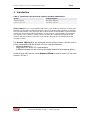
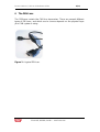
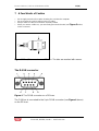
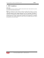
Philips Kvaser LAPcan is a PC card compliant with the PC-Card (PCMCIA) standard, containing the powerful microcontroller C161O from Infineon and two SJA1000 CAN controllers from Philips. The SJA1000 handles CAN messages with 11 bit as well as 29 bit identifiers. It can both detect and generate error frames on the CAN bus, and provides two completely independent CAN channels with two separate connectors. The CAN bus transceivers are integrated into the connection cables.
Philips Kvaser LAPcan is a PC card compliant with the PC-Card (PCMCIA) standard, containing the powerful microcontroller C161O from Infineon and two SJA1000 CAN controllers from Philips. The SJA1000 handles CAN messages with 11 bit as well as 29 bit identifiers. It can both detect and generate error frames on the CAN bus, and provides two completely independent CAN channels with two separate connectors. The CAN bus transceivers are integrated into the connection cables.


-
 1
1
-
 2
2
-
 3
3
-
 4
4
-
 5
5
-
 6
6
-
 7
7
-
 8
8
-
 9
9
-
 10
10
-
 11
11
-
 12
12
-
 13
13
-
 14
14
-
 15
15
-
 16
16
-
 17
17
-
 18
18
-
 19
19


Philips Kvaser LAPcan User manual
- Category
- Networking
- Type
- User manual
- This manual is also suitable for
Philips Kvaser LAPcan is a PC card compliant with the PC-Card (PCMCIA) standard, containing the powerful microcontroller C161O from Infineon and two SJA1000 CAN controllers from Philips. The SJA1000 handles CAN messages with 11 bit as well as 29 bit identifiers. It can both detect and generate error frames on the CAN bus, and provides two completely independent CAN channels with two separate connectors. The CAN bus transceivers are integrated into the connection cables.
Ask a question and I''ll find the answer in the document
Finding information in a document is now easier with AI