Page is loading ...

SB4800/SB4800HB Models
Woodburning Fireplaces
Installation, Operation and Maintenance Manual
For Residential Installation
ONLY unvented gas log sets which have been found to comply with the Standard for Unvented
Room Heaters, ANSI/IAS/AGA Z21.11.2, are to be installed in this fireplace.
When an approved ANSI/ISA/AGA Z21.11.2 unvented room heater is installed in this fireplace, an
H2853 canopy must also be installed.
WARNING: DO NOT operate an unvented gas log set in this fireplace with the chimney re-
moved.
Underwriter’s Laboratories, Inc.®
This fireplace is U.L. listed for use with the
“L” Series Chimney System components.
53D9025

2
53D9025
CONTENTS
Congratulations!
You have chosen the finest wood burning fireplace available. Your fireplace has been designed for years of heating
and viewing enjoyment. Please take time to read this entire manual before installing or operating your fireplace.
Table of Contents
Listing and Code Approvals ..........................................................................................................................1
Important Information ...................................................................................................................................2
Operation Guidelines ....................................................................................................................................3
Clearances ................................................................................................................................................4-6
Fireplace Location ........................................................................................................................................7
Installation Preparation ..............................................................................................................................8-9
Floor Protection .....................................................................................................................................10-11
Fireplace Components ...............................................................................................................................12
Fireplace Installation ..................................................................................................................................13
Chimney Installation ..............................................................................................................................14-15
Chimney Offset Installation ....................................................................................................................
16-17
Chimney Cap Installation ......................................................................................................................18-19
Chimney Cap Chase Installation ................................................................................................................20
Outside Combustion Air Precautions and Recommendations ...............................................................
21-22
Combustion Air Assembly ...........................................................................................................................
23
Gas Appliance Installation .....................................................................................................................
24-25
Trim and Door Installation ..........................................................................................................................
26
Fireplace Operation ...............................................................................................................................27-28
Maintenance and Safety ........................................................................................................................29-31
Repair Parts Diagram and List ..............................................................................................................32-33
Warranty ................................................................................................................................................
34-35
Listing And Code Approvals
The instructions contained in this manual provide the information necessary to install this fireplace in accordance with
Underwriter’s Laboratories requirements and in compliance with the National Fire Protection Association Standard No.
211. Some codes may require the fireplace and chimney be electrically grounded. Before beginning the installation, you
should check with local building officials to obtain required permits and assure compliance with local regulations and
coded. If you encounter problems with code requirements, contact your dealer for assistance.
These Fireplace models are listed by Underwriters Laboratories, Inc. to U.L. 127-standard for factory-built fireplaces.
The design of this fireplace and these instructions complied with applicable safety standard for a factory built fireplace
in effect at the time the fireplace was manufactured. You should be aware, however, that failure to install, operate, and
maintain this or any other factory built fireplace properly can result in a house fire or other occurrences that could cause
deaths, injuries, and property damages. It is very important that the persons installing and/or supervising the installation
of this fireplace have appropriate skills in using the tools and techniques required; and reading and comprehension skills
sufficient to read and follow these instructions. These instructions contain warnings, cautions, and notes to emphasize
important safety information. To assure that safe and satisfactory service is received from this fireplace, please read the
following special notices and all the contents of this manual.

53D9025
3
IMPORTANT SAFETY INFORMATION
Installer Owner
Please leave these instructions with the owner. Please retain these instructions for future reference.
1. Read these instructions entirely before beginning any part of the installation. Save these instructions for any future
repairs.
2. Use these instructions as a guide during the installation of the fireplace.
3. Be sure these instructions become the property of and are reviewed by all future users of this fireplace to encourage
proper operation and maintenance.
4. All the parts used with this fireplace system must be installed in accordance with these installation instructions. Fail-
ure to do so may be hazardous and will void the warranty.
5. This fireplace and accessories should not be altered in any way that is not specifically recommended in this manu
-
al.
6. Refer to your local building code for local requirements pertaining to installation of factory-built fireplaces. These
fireplaces are intended for installation and use according to standard NFPA NO.211 of the National Fire Protection
Association.
7. This fireplace must not be installed with a masonry flue.
8. This fireplace and chimney should not be used for venting a wood or coal burning heater or fireplace insert.
WARNING: Do not install a separate solid fuel insert or gas fireplace insert into this fireplace and chimney system
without written authorization.
9. WARNING: Do not pack required air spaces with combustible material or insulation not specifically recommended
for use in such areas.
Intended Product Usage
The fireplace is designed to sit directly on a combustible floor. The fireplace must be installed with clearances to com-
bustible building materials specified in this manual. Only parts manufactured by MHSC and labeled for use with the fire-
place should be used in the installation of this fireplace except for special roof flashings that may be fabricated locally.
The use of improper parts in the installation can be hazardous and voids the warranty offered by MHSC.
This fireplace is designed to burn wood. This fireplace is not designed to burn coal, unplumbed liquid fuels, unplumbed
gaseous fuels or household refuse. Any attempt to burn these fuels in the fireplace can be hazardous.
Failure to heed usuage warnings may cause a fire hazard and will void the Warranty. This fireplace is intended for
supplemental heating only and is not intended for use as a primary heating system. For use with Solid Wood Fuel, UL
Classified Processed Solid Fuel Fire Logs, or Certified Decorative Gas Appliance.
“Do not use a fireplace insert or other product not specified for use with this fireplace.”
Improper Installation
Improper installation or use of this fireplace will void the warranty and can cause:
1. Damage to the fireplace from overheating.
2. Hazardous temperatures to develop on combustible materials adjacent to the fireplace or chimney.
3. The emission of smoke, sparks or hazardous gases into the dwelling.
4. Leakage of rain water into the dwelling.

4
53D9025
OPERATION GUIDELINES
When a AK4 combustion air assembly and a combustion air duct are attached to the con-
necting point on the left of the fireplace, combustion air may enter the firebox through a
dampered opening behind the left side panel. This feature is designed for your benefit to
reduce the room air used for combustion and to prevent excessive loss of heat from the
room. When the fireplace is in use, this damper should be open. When the fireplace is
not in use, the damper should be closed to prevent cold air from entering the firebox. The
combustion air damper is open when the lever, located on the left side of the firebox near
the top of the left firebrick, is up and closed when the lever is down.
Outside air for combustion is optional unless required by federal, state or local building
codes. See the section of this manual providing the instructions for installation of the
combustion air assembly. The design of the fireplace allows the routing of the combus-
tion air duct up, down, or horizontally to obtain the outside combustion air. This permits
flexibility in planning your installation. Refer to Figure 25 for typical installation methods.
Review the precautions and recommendations in this manual pertaining to outside com-
bustion air installation.
Glass doors should be installed to receive the maximum benefit from your fireplace. For
large fires, the maximum heating benefit from the fireplace will be obtained with the doors
open due to the high amount of radiant heat being emitted out of the front opening of
the fireplace. With a small fire, or before retiring in the evenings, it is best to operate the
fireplace with the doors closed to prevent excessive room air form being drawn up the
chimney. When the doors are open, the mesh screens should be closed to help keep
burning embers from popping out of the firebox.
The fireplace should also be equipped with a flue damper, which must be open when
the fireplace is in use. The flue damper control lever is located inside the fireplace. The
counterweighted damper is operated by simply pushing up to open or pulling down to
close the damper. When the fireplace is not in use, the damper should be closed to pre-
vent cold air form entering the chimney as well as preventing warm air in the room from
escaping up the chimney.
NOTE: It is normal for a small amount of smoke to be released from the upper portion
of the fireplace the first few times you use your new fireplace. This results from an oil
residue on the metal. Open a door or window to allow the smoke to escape.
The grate included with this fireplace helps to appropriately locate and contain the burn-
ing wood. Failure to use this grate may cause overheating of parts of the fireplace and
allow large pieces of burning wood to roll forward out of the firebox. If the grate becomes
warped or damaged, it must be replaced with grate number 052874 only.
WARNING: Fireplaces equipped with doors should be operated only with the doors fully
open or doors fully closed. If doors are left partly open, gas and flame may be drawn out
of the fireplace opening, creating risks of both fire and smoke.
All fireplace chimneys are in direct contact with cold air on the exterior of the structure.
Consequently, when the fireplace is not in use, cold air can fall down the chimney of the
fireplace to cool off the fireplace chase. Therefore, the fireplace chase must be insu-
lated to minimize the risk of cold air infiltration to the home. Even if the fireplace chase
is adequately insulated, this cannot completely ensure that cold air infiltration into the
structure will be eliminated. Cold air infiltration is a possibility with any fireplace or device
that freely communicates with the air on the outside of the structure. Today’s homes are
more energy-efficient and, therefore, better insulated and tightly constructed. Unfortu-
nately, when air is removed from the house, as by a bathroom fan, or consumed by a
furnace, additional air is needed to replace the air consumed. Unless the additional air
is supplied, this can cause a negative pressure in the home. When this happens, the
house will draw in outside air form the cracks in the windows, down the fireplace flue or
other locations of air leakage in the home. Because cold air infiltration may be unavoid-
able in some structures, MHSC is not responsible for heat loss or air infiltration through or
around the fireplace.

53D9025
5
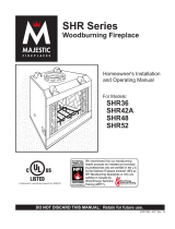
PRODUCT FEATURES
48”
52”
FP1875
SB4800 features
8/08
Figure 1
Residential Installation
Model LC
Chimney Cap
Roof Flashing
Model 612
(Flue Outlet Height)
Storm
Collar
15 ft. = Min. Height (No offsets)
15 ft. = Min. Height (2 30° Elbows)
21 ft. = Min. Height (4 30° Elbows)
86 ft. = Max. Height (Chimney support
every 25 ft.)
L12 (1 ft. pipe)
L18 (1¹⁄₂ ft. pipe)
L36 (3 ft. pipe)
L48 (4 ft. pipe)
Maintain 2” Minimum Air Space Be
-
tween Chimney and Combustibles
Fireplace Model
SB4800
Flexible Duct
Type FP-4-U
Combustion Air
Assembly
Nail to Framing Members
Galvanized Metal Strip
CAUTION: Do Not Restrict Side Air Inlet Vents
with Surround or Trim Materials
(Floor Line)
Top Spacer
Firestop Model LF-FS-2
(Requires 17 x 17 framing)

6
53D9025
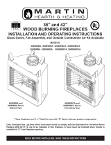
FIREPLACE DIMENSIONS
28”
11” Inside
Diameter Flue
9”
26
”
16
”
9/16”
4”
4”
38”
47
”
13” Outside
Diameter
Outer Pipe
1/8”
6”
11
”
27”
8”
35
”
52
”
10”
8”
11
”
15
”
53D9025
SB4800 dims
8/08
Figure 2
70
11
11
17
17
35
35
47
47
SCALE:
1/2" = 1'0"
SCALE:
1/4" = 1'0"
L36
70 Linear Gain
52
52 Linear Gain
34
34 Linear Gain
L36 L36 L18
L18 L36 L48L12
L18 L18
47
47
L48
20'5" Linear Gain
20.5
35
35
L36
70
L36
L36
70 Linear Gain
52
52 Linear Gain
34
34 Linear Gain
L36 L36 L18 L18 L18
11
11
L12
17
17
L18
Front
Right Side
Gas Line
Opening
Outside Air
Opening

53D9025
7
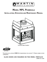
CHIMNEY SECTION DIMENSIONS
6
3
L
6
3
L
39”
76”
6
3
L
8
1
L
30”
61
”
8
4
L
56”
27
”
46”
6
3
L
21”
30”
8
1
L
12”
25”
2
1
L
9”
16”
0
3
E
L
w
o
b
lE
4”
6
3
L
6
3
L
6
3
L
8
1
L
8
4
L
6
3
L
8
1
L
2
1
L
0
3
E
L
w
o
b
l
E
SCALE:
1/2" = 1'0"
SCALE:
1/4" = 1'0"
NOTE: Dimensions May Vary Slightly De to Manufacturing Tolerances.
46”
21
”
39”
30”
27”
76”
61”
56”
12”
9”
4”
30”
25”
16”
FP1877
elbows dims
8/08

8
53D9025
FIREPLACE LOCATION
This fireplace does not weigh more than large pieces of furniture and can normally
be located near a load bearing wall without requiring additional foundations or sup-
ports. If however, the fireplace is to be trimmed with a heavy stone or brick facing
and hearth extension, be sure the supporting structure is adequate.
Figures 3 and 4 provide dimensional details of the fireplace, required spacing to
combustible walls, and some suggested fireplace locations. When selecting a loca
-
tion, choose one that is away from frequently opened doors, central heat outlets or
returns, or other places where air movements may disturb the airflow around the
fireplace. Air turbulence near the fireplace may cause smoke to spill out of the fireplace opening.
CAUTION
Do not install fireplace
over carpeting.
60” Minimum
19”
Min.
47
”
85” Minimum
19
”
Min.
27”
Minimum
23” Min.
28” Minimum
Screened
Opening
70” Minimum
*16”
1” Minimum Air Space Clearance
FP1879
opening dims
8/08
*Applies when Glass Doors are installed
Figure 3
Corner Installation
Side Wall Installation
Figure 4
Full Projection
Corner
Flush

53D9025
9
INSTALLATION PREPARATION
Survey the planned location for the fireplace for overhead plumbing or electrical wires, etc., that might complicate the
installation or endanger persons installing or cleaning the chimney. Avoid a location where the chimney cap will be
near abrupt changes in the roof shape, nearby wall or embankments, under or near trees or above the roof of a single
story wing of a two story building as shown by Figure 7. All these conditions can cause turbulence or pressure condi-
tions that can cause poor chimney draft and smoke spillage from the fireplace opening. Elbows may be used to offset
the chimney to avoid obstructions or to locate the chimney cap in a preferred location. Refer to the sections of this
manual pertaining to chimney offsets for instructions on proper elbow use. Poor installation or location of the chimney
cap and/or components can cause wind blown rain to enter the chimney.
Be sure the selected location will allow a 17” square combustible material-free space for the chimney to pass through.
If the chimney is to pass through living or storage spaces, be sure there is adequate space to enclose the chimney
to avoid personal contact with, or damage to, the chimney. If the fireplace is to be installed on an outside wall, the
surrounding walls (chase) should be constructed and insulated as shown by Figure 5. Failure to insulate the fireplace
form outside temperatures will cause heat loss through and around the fireplace.
8’ 0”
Level
FP1880
install prep
8/08
Figure 5
Joint Insulate
Same as Ceiling
Refer to
Notes
Firestop Spacer
LCL Telescoping
Chimney Cap
LCLF Flat Chase
Top Flashing
Chimney Sections “L” Series
Insulate Outside
Walls of Chase
Solid Continuous
Surface
Insulation
(Thermal Barriers)
Outside Base
NOTES:
1. Model LF-FS-2 Firestop Spacer must be used.
2. Local codes may not require fire stopping at
the ceiling level for chase installations, but it
is recommended for safety and reducing heat
loss.
3. Do not insulate the chase with blown or fill
type insulation. Insulation should only contact
the fireplace at points where the fireplace
would normally be contacted by framing mate-
rials.

10
53D9025
INSTALLATION PREPARATION
Figure 7
Preferred Location
Poor Location
18 ft. Min.
FP1881
single story install
8/08
Figure 6
Single Story Installation with Attic Space
LC Chimney Cap
Storm Collar
Flashing
(612 or 1212)
17”
Square
Opening
in Joist
2” Min. Clearance to
Combustibles
“L” Series Chimney
Components
Firestop Spacer LF-FS-2 (2” Air
Space Clearance to Combustibles)
Attic Space
3’ Min. or 2’ Above
Any Point Within 10’
Flue Outlet Height
See Table 1
for Roof Open-
ing Size
3 ft. Min.
FP1883
multistory install
8/08
Figure 8
Multiple Story Installation
Model LC
Chimney Cap
Storm Collar
(Included with cap)
Flashing
(612 or 1212)
See Table 1 for
Roof Opening
Size
Attic Space
Firestop Spac-
er LF-FS-2
(2” Air Space
Clearance to
Combustibles)
2” Clearance to
Combustibles (Min.)
17” Square
Opening in
Joist
Max.
Installation
Height - 86
ft. Chimney
Third Floor
Area
Second
Floor Area
First Floor
Area
Flue Outlet Height
17” Square
Opening in
Joist
17” Square
Opening in
Joist
Firestop Spac-
er LF-FS-2
(2” Air Space
Clearance to
Combustibles)
Firestop
Spacer
LF-FS-2 (2”
Air Space
Clearance to
Combus-
tibles)

53D9025
11
FLOOR PROTECTION
If this fireplace is installed on a combustible floor, the floor area 20 inches in front of, and 12 inches either side of the
fireplace opening must be protected by an insulating noncombustible hearth extension. This hearth extension may
be either minimum 6-inch thick stone or brick as shown by Figure 9, an H2068 hearth extension kit or a locally con-
structed equivalent to the H2068.
The H2068 hearth extension kit consists of sufficient insulation board to cover the 20” x 68” floor area with ° inch layer
of insulation. A 20” x 68” piece of galvanized steel is included in the kit to cover the insulation before a finishing layer
of noncombustible material of stone, brick, tile, etc., is applied to finish the hearth extension.
The insulation used in the H2068 hearth extension has a thermal conductivity (K factor) of 0.43. If you do construct a
hearth extension equivalent to the H2068, be sure the insulation you use has enough compressive strength to support
the weight of the covering materials and persons standing on it, and insulating qualities equal to or better than the 1/2”
covering provided by the H2068.
Alternate brick or stone hearth
extension for use with the SB4800
fireplace when placed over a
combustible floor without insulation
board protection.
Figure 9
12”
Min.
SB4800 Fireplace
Hearth
Brick or Stone Hearth
Extension
(62” Long Minimum)
6” Min. Brick or
Stone from Top
of Platform
Safety Strip is required when
unit is placed on combustible
floor or platform.
12”
Min.
20” Min.
62”
20”
12”
12”
FP1885
hearth extension
8/08
Figure 10
Fireplace and Hearth Extension
- Top View
MHSC H2068 Hearth Extension or
Equivalent
NOTE: A hearth extension placed on a combus-
tible floor must be constructed with rigid insula-
tion which has minimum “R” value of 1.16 or a “K”
value of .86. The insulation must be covered with
a non-combustible covering such as tile stone,
marble or a piece of .018 minimum sheet meal
which is needed to protect the insulation. Follow
instructions provided with the fireplace for all oth-er
specifications and directions for proper instal-lation
of the fireplace and hearth extension.

12
53D9025
FLOOR PROTECTION
The ability of insulating material to retard the transfer of heat may be expressed as either Thermal Con-
ductance (C), Thermal Conductivity (K), or Thermal Resistance (R). The mathematical relationship of
these values and the formulas for converting one value to another is as follows:
C=K divided by the material thickness
(Example C = .43 divided by 1/2 (.50)
C = .86)
K = C multiplies by the material thickness
(Example K = .86 multiplied by 1/2 (.50)
K = .43)
R= The material thickness divided by K
(Example R = 1/2 (.50) divided by .43
R = 1.16)
26”
53
”
27”
52
”
20”
68”
FP1886
hearth protction
8/08
Figure 11
Metal Safety Strip
Combustible
Floor
Hearth Protector
WARNING: The hearth extension and
the metal safety strip should be in-
stalled only in a horizontal relationship
to the fireplace, as illustrated.
12”
Min.
12”
Min.
20” Min.
FP1887
hearth extension
8/08
Figure 12
Top of Raised
Hearth
Floor Line with
Raised Hearth
Hearth Extension
Metal Safety Strip
With either type hearth extension minor shifting of the supporting floor or expansion and contraction may
eventually cause a crack to develop between the hearth extension and the face of the fireplace. To help
prevent the crack from developing, the hearth extension materials must be firmly fastened in place. Wall
ties should be screwed to the face of the fireplace and imbedded in the mortar joints of brick, stone, or
other non-combustible materials. The metal safety strip packed with the fireplace must be placed be-
neath the fireplace and extended under the hearth extension or into a mortar joint of the hearth extension
as shown by Figures 9 and 11. In the event a crack does eventually develop, the metal safety strip will
serve as a barrier to prevent sparks or embers from falling from the fireplace onto combustible flooring
materials.

53D9025
13
FIREPLACE COMPONENTS
SB4800 SB4800HB
WSB48
Glass Doors
LCS
Chimney
Support
LE30
30° Elbow Set
H2068
Hearth
Extension Kit
LF-FS-2
Firestop
Spacer
612-1212
Flashing
AK4
Combustion
Air
Assembly
LC
Chimney Cap
LC
L
Telescoping
Chimney Cap
L48 L36 L18 L12
Chimney Sections
LCLF Flat flashing
36"x72" (13.5" Diameter Hole)
Model Number Description
SB4800 44 inch front opening fireplace. Includes wire firescreen, sealing flue damper and outside com-
bustion air capability. When installed, outside combustion air can be connected to left side.
See installation instructions for details.
NOTE: HB models have herringbone brick pattern.
L48 4-foot chimney section (11-inch diameter flue/13” dia. outer pipe)
L36 3-foot chimney section (11-inch diameter flue/13” dia. outer pipe)
L18 1
¹⁄₂-foot chimney section (11-inch diameter flue/13” dia. outer pipe)
L12 1-foot chimney section (11-inch diameter flue/13” dia. outer pipe)
LE30 One pair of 30-degree elbows. Maximum-two pairs (4 elbows per chimney)
LCS Chimney support (required when chimney height exceeds 30 feet)
LC Round chimney cap for contemporary installation. Includes storm collar.
LCL Round telescoping chimney cap. For use with flat chase top terminations.
612 0-6/12 pitch flashing for contemporary installation.
1212 6/12-12/12 pitch flashing for contemporary installation.
LF-FS-2 17-inch firestop spacer. One required at each ceiling or floor level.
LF-FS-30 Firestop spacer-for 30 degree chimney incline through ceiling or floor.
FP-4-U 4-inch insulated combustion air duct-8-foot lengths.
403 4-inch duct connector (for splicing FP-4 ducts). Includes two clamps.
LCLF 3’ x 7’ Flat chase flashing. For use with LCL chimney cap.
AK4 4-inch outside combustion air assembly.
WSB48 Optional polished brass glass door kit.
H2068
Hearth extension-protects floor against sparks and radian heat (residential installation) 20” x 68”.

14
53D9025
FIREPLACE INSTALLATION
Location Selection
Unpack and check the fireplace and chimney for damage. If any items have been damaged,
report this to your dealer. Before beginning the installation, be sure you have the proper parts
in sufficient quantity. Refer to Figure 26 for proper identification of parts.Do not substitute parts.
Use only parts listed for use with the Model SB4800/SB4800HB fireplaces.
Fireplace Installation
1. Refer to Figure 1 for an example of a typical installation of the fireplace components.
2. Be sure the location of the fireplace will provide the required clearances indicated by Figures 2,
& 3 and the minimum chimney air space clearance to combustibles of two inches.
3. Set the fireplace in the desired location and be sure it is securely supported and leveled.
Check the face of the fireplace with a carpenter’s level and if it is not plumb; correct it by plac
-
ing shims under the edges of the fireplace.
4. Block in the fireplace to prevent any shifting of the firebox. Secure the fireplace with nails or
screws through the flanges located on each side of the fireplace. Do not enclose the fireplace
until the combustion air duct and chimney pipes are installed.
NOTE: Some local codes may require electrically grounding the fireplace and chimney.
Chimney Installation
In order to assure safe and satisfactory performance of the fireplace, it is very important to
properly install the chimney. This is an important part of the installation and the sections of this
manual pertaining to chimney installation should be reviewed very thoroughly.
For your safety, some of the important things to remember in regard to chimneys are listed below:
1. Use only parts and accessories labeled for use with this fireplace.
2. Use only undamaged parts and accessories.
3. Enclose the chimney where it passes through the living spaces to prevent contact with and
possible dam-age to the chimney.
4. Install firestop spacers at each ceiling level.
5. Install the proper chimney cap or chimney housing on the chimney to prevent the entry of rain
and debris into the chimney and to assure the proper venting of smoke.
6. Do not use more than four elbows in the chimney.
NOTE: To select the proper chimney height, refer to Figure 1. The flue outlet must be a mini-
mum of three feet above the highest point where the chimney penetrates the roof and a minimum
of two feet above all portions of the building within ten feet. If the chimney is to include elbows to
offset the chimney, refer to the Chimney Offset and Cap Installation section of this manual. There
must be at least two inches air space between all sections of the chimney and combustible mate-
rials between floors.

53D9025
15
CHIMNEY INSTALLATION
24” MIN.
36”
24” MIN.
36”
10'
10'
FP1889
chimney location
8/08
Figure 14
NOTE: Flue outlet should be two feet above all portions of the
building within ten feet as shown in the illustration. The chimney
must not extend more than 90 inches above the roof without ad-
ditional support.
1. Lay out, cut and frame openings through all ceilings and the roof at the point where the chimney
will pass through. Unless the chimney is to be offset, the point where the center line of the chim-
ney will pass through the ceiling and roof can be determined with a plumb line as shown by Figure
15. The fireplace should be located in the planned installation position. After the center line is es-
tablished and a nail is driven to mark the point, the opening can be cut if you are satisfied with the
chimney location relative to ceiling and roof joists and/or any other obstructions. The roof opening
center line should be marked by driving a nail through the roof from underneath that will penetrate
the roof and can be located from the rooftop. If the chimney is to penetrate a pitched roof, the hole
in the roof must be rectangular instead of square and should be sized according to Table1.
2. Install the firestop spacer as required from beneath the ceiling unless the space above is attic
space. In an attic, the firestop spacer should be installed at the floor level of the attic. You must
have joists or headers on all four sides of the spacer and use a minimum of four 8-penney nails to
secure the spacer.
3. To install the “L” series chimney sections, insert the male end of the flue, the smallest diameter
pipe, into the flue outlet of the fireplace and press down until the snap locks engage. Continue the
process, adding the chimney sections on top of each other until the chimney is at least six inches
above the roof opening on all sided. As the chimney sections are installed, check each joint to
make sure it is properly locked to the previous section. If additional strength of the outer pipe joints
is desired, you may use two or three sheet metal screws placed through the area where the outer
pipes overlap one another. To install these screws, drill a 1/8-inch diameter hole through the chim-
ney sections, taking care not to penetrate the inner flue pipe. WARNING: Be very careful when
drilling the holes into the outer pipe. The drill must not penetrate the inner stainless steel pipe.
NOTE: If you intend to have a total fireplace installation of more that 30 feet you must use chimney
support model LCS at or below 30 feet to support the weight of additional chimney pipe.
To install the chimney support, place the crimped end of the flue and outlet air duct portions into the
last section of chimney pipe. Push down until the outside or inlet air duct of the chimney support over-
laps and snap locks the chimney support into the chimney section.
Nail the support straps tightly to a building frame member or ceiling joist as shown by Figure 16. You
must use at least two 8-penney nails per strap.

16
53D9025
CHIMNEY INSTALLATION
Centerline of
Chimney
Figure 15
Actual Center Point
Plumb Line
Plumb Bob
Imaginary Center
Point
Minimum Required Roof Opening
Minimum Framed Opening
“L” Series
Roof Pitch Doublewall Chimney
0/12 17” x 17”
1/12 17” x 17” 1/8”
2/12 17” x 17” 1/4”
3/12 17” x 17” 1/2”
4/12 17” x 17” 3/4”
5/12 17” x 18” 1/4”
6/12 17” x 18” 3/4”
7/12 17” x 19” 3/8”
8/12 17” x 20”
9/12 17” x 20” 5/8”
10/12 17” x 21” 3/8”
11/12 17” x 22” 1/4”
12/12 17” x 23”
Figure 16
Outer Pipe
Flue
Support Straps
Fasten Securely
Firestop
Chimney Support
Snap Lock Chimney
Support Securely to
Lower pipes Before
Fastening Support
Straps
Figure 17
Firestop Spacer Installation at Attic Level
Inlet Air Pipe
Ceiling Joist
Flue Pipe
Firestop Spacer
Chimney Section
Header
Firestop Spacer Installation at Floor Levels
Floor
Joist
Inlet Air Pipe
Flue Pipe
Firestop Spacer
Chimney Section
Header

53D9025
17
CHIMNEY OFFSET INSTALLATION
Elbow Installation
The following are important points that should be observed when installing elbows on the fireplace:
1. The support straps of all elbows not installed directly on top of the fireplace should be nailed se-
curely to the surrounding structure. This allows the support strap to carry the weight of the chim-
ney above the elbow and prevents this weight from breaking the elbow or chimney sections apart.
2. Elbows should not be used in any combination that inclines the chimney more than 30 degrees
from vertical.
Figure 18
Inlet Air
Pipe
Flue
All four (4) support straps
must be nailed on to fram-
ing member around the
elbow with a minimum of
two (2) 8-Penny nails per
strap
NOTE: Although both halves of the
elbow set may have tie straps, only
the top half must be secured. The
bottom elbow half is not required to
be secured for added stabilization of
pipe.
3. The limitations on the quantity of elbows per chimney are as follows: If the total height of the
fireplace and chimney is—12’ - 2” or more — two elbows may be used in the chimney. 21’ - 0” or
more — four elbows may be used in the chimney.
4. The inclined portions of chimneys that pass through living spaces likely to be used for storage
should be enclosed to avoid contact with and possible damage to the chimney. The minimum air
space of two inches between the chimney and enclosing materials must be maintained.
5. The length of the inclined portion of chimney between elbows must not exceed 6 feet when unsup-
ported or 20 feet if the chimney is supported at six-foot intervals with support such as metal sup-
port straps.
6. When enclosing the elbows and inclined portions of the chimney, enclosing materials must be
installed vertically to maintain the required two-inch minimum air space clearance to the chimney
at the extremities of the offset. It is recommended that enclosing material not follow the inclined
portions of the chimney.
Offset Installation Sequence
1. Determine the location and amount of offset required, then select the combinations of chimney
sections and elbows required from the offset chart. Refer to Page 19.
2. Install the first LE30 elbow by placing the extended flue into the mating part of the fireplace or
chimney section. Push down until the outside or inlet air duct of the elbow overlaps and the snaps
lock the elbow into the fireplace or chimney section.
3. Nail the support straps to the framing member with a minimum of two 8-penny nails per strap.
4. Install the sections of pipe between elbows until the proper number of chimney sections have been
installed.
5. Install the second elbow to return the run of the chimney to vertical.
6. Nail the support straps of the second elbow to a building frame member.
7. Continue installing the vertical portion of the chimney.
NOTE: If the inclined portion of the chimney passes through a floor or ceiling, an LF-FS-30 firestop
spacer should be installed to provide the firestop and support required. Be sure proper spacing in
maintained between the chimney and combustibles.

18
53D9025
CHIMNEY OFFSET AND CAP INSTALLATION
17”
22
”
7”
30°
7”
FP1894
firestop spacer
8/08
Figure 19
Centerline of
Chimney
C
L
Continue chimney to proper
height and install round chmney
cap or chimney housing
Firestop Spacer as
Required
Fasten Suport Straps
Securely
NOTE: Two (2)
elbows may be used
when total installatin
height exceeds 24’2”
Storm Collar
Flashing
Roof
2” Minimum Air
Space Clearance
to Combustibles
with use of LF-FS-2
Firestop
C
L
C
L
Continue chimney through roof
and install round chimney cap
or chimney housing
Firestop Spacer 2” Minimum Air Space
Clearance at Jois. (“L” Sries Chimney)
Vertical Chimney
Enclosure
Chimney Must Be Enclosed in
Accessible Areas
Firestop Spacer
Diagonal Chimney
Enclosure
RISE
Firestop Spacer 2”
Air Space Clearance
to Combustibles
NOTE: Four (4) elbows may be
used when toatl installation height
exceeds 24 ft.
Maximum four (4) elbows Per
Fireplace
Offset Max 10’
Support Straps
Diagonal Chimney
Enclosure
Vertical Chimney Enclosure
Recommended.
Diagonal Chimney Enclosure
Acceptable
Fasten All Support
Straps Securely
Vertical Chimney
Enclosure
Support Straps Not
to Penetrate Firestop
Hold 13” Diameter
(Outside) Pipe Vertical
Scribe Line
at Bottom
NOTE: LCL chimney cap is same as LC
with the exception of a longer telescop-
ing pipe which may be needed for special
installations such as chase installations.
*36”
18
”
FP1898
chimney cap install
8/08
Model LC
Chimney
Cap
Apply Mastic Here
Storm Collar
Flashing
* or 2” Above Any Point Within 10’

53D9025
19
CHIMNEY CAP INSTALLATION
Model LC Chimney Cap
SPECIAL NOTE: The proper height as previously explained is important to assure proper draft and
safety. The chimney cap extends the flue outlet four inches above the top of the last section of chim-
ney. This should be kept in mind when determining the proper height for the chimney. The chimney
should not be extended more than 90 inches above the supporting roof structure without additional
support. In the case of an “A” frame type construction or other steep pitch roofs that require more
than 90 inches of chimney above the roof, a support should be attached to the chimney at the 90 inch
level that is strong enough to support a wind load of 3-1/8 pounds for each inch the chimney extends
above 90 inches. The flue outlet must be a minimum of three feet above the point where in penetrates
the roof.
CAUTION: Be careful to avoid electrical shock hazard when contacting wires to the metal chimney
components.
1. Extend the regular chimney sections until the top of the chimney is 4 inches below the total flue
height desired. Do not snap the last section of inlet air duct or largest diameter pipe in place until
Step 3 is completed.
2. Remove the shingles from around the chimney so that the flashing may be installed, with the up-
per part of the flashing under the shingles.
3. Set the flashing on the roof. Hold a section of the outside pipe (13” diameter) on the flashing and
scribe a line around the flashing, then cut the top off the flashing by cutting 1/4 inch below the
scribed line. This should increase the diameter of the flashing outlet sufficiently to allow the flash
-
ing to be placed over the chimney. See Figure 19.
4. Snap the last section of inlet air duct in place and slide the flashing over the chimney. Adjust the
chimney to assure that the proper minimum clearances are maintained.
5. Nail the flashing securely in place with eight nails.
6. Seal the crack between the top of the flashing and the chimney with mastic. Leave some excess
mastic at this area to be used in step eight. NOTE: Use pliers and wear gloves when performing
step seven to minimize the danger of cutting your hands on the edge of the storm collar.
7. Place the storm collar around the chimney and put the collar together like a belt in belt loops.
Slide the end of collar under the two loops on the other end with the loops facing up. Overlap the
ends of the collar until it is tight against the chimney. Bend the free end of the collar back over
the loops to hold the storm collar securely together. The excess end of the storm collar may be
trimmed off.
8. Slide the storm collar down snugly against the flashing until the excess mastic left in step six is
forced up into the crack between the storm collar and the chimney. This should make the joint
between the flashing and the chimney watertight.
9. Install the chimney cap by placing the cap into matching parts of the last chimney section. Then
punch or drill 1/8 inch diameter holes in the inlet air duct (chimney pipe) where specified on the
brackets and fasten it down with the No. 8 screws provided. Do not penetrate the inner stainless
steel pipe while installing the screws.
10.Check all the parts of the fireplace, chimney and chimney termination cap to assure that no parts
have been damaged or bent during installation and that all parts have been installed properly.
NOTE: The metal used for the chimney cap has a rust protective coating but the cut edges of the
parts are not protected. To prevent rusting and rust staining of nearby structures, exposed parts of the
chimney and chimney cap should be detergent washed and painted with a galvanized primer paint.

20
53D9025
CHIMNEY HEIGHT AND OFFSET CHARTS
Intermediate
Height Sections
(Inches) 1” 1
¹⁄₂’ 3’ 4’
35 0 0 1 0
39 2 1 0 0
47 0 0 0 1
52 0 1 1 0
58 1 0 0 1
64 0 1 0 1
70 0 0 2 0
75 1 1 0 1
82 0 0 1 1
87 0 1 2 0
94 0 0 0 2
99 0 1 1 1
105 0 0 3 0
111 0 1 0 2
117 0 0 2 1
122 0 0 2 1
129 0 0 1 2
134 0 1 2 1
141 0 0 0 3
146 0 1 1 2
152 0 0 3 1
158 0 1 0 3
164 0 0 2 2
169 0 1 3 1
176 0 0 1 3
181 0 1 2 2
188 0 0 0 4
193 0 1 1 3
199 0 0 3 2
205 0 1 0 4
211 0 0 2 3
216 0 1 3 2
223 0 0 1 4
228 0 1 2 3
235 0 0 0 5
240 0 1 1 4
246 0 0 3 3
252 0 1 0 5
258 0 0 2 4
263 0 1 3 3
270 0 0 1 5
275 0 1 2 4
282 0 0 0 6
287 0 1 1 5
293 0 0 3 4
293 1 0 0 6
305 0 0 2 5
310 0 1 3 4
317 0 0 1 6
322 0 1 2 5
329 0 0 0 7
334 0 1 1 6
340 0 0 3 5
346 0 1 0 7
352 0 0 2 6
357 0 1 3 5
364 0 0 1 7
369 0 1 2 6
376 0 0 0 8
Elbow Chimney Sections Total In.
Set 1’ 1¹⁄₂’ 3’ 4’ Offset
1 0 0 0 0 4¹⁄₂ 17
1 1 0 0 0 10 26
¹⁄₂
1 0 1 0 0 13 31³⁄₄
1 2 0 0 0 15
¹⁄₂ 36
1 1 1 0 0 18¹⁄₂ 41¹⁄₄
1 0 0 1 0 22 47¹⁄₄
1 2 1 0 0 24 50
³⁄₄
1 0 0 0 1 28 57³⁄₄
1 0 1 1 0 30
¹⁄₂ 62
1 1 0 0 1 33¹⁄₂ 67³⁄₄
1 0 1 0 1 36¹⁄₂ 72¹⁄₂
1 0 0 2 0 39
¹⁄₂ 77¹⁄₂
1 1 1 0 1 42 82
1 0 0 1 1 45
¹⁄₂ 88
1 0 1 2 0 48 92¹⁄₄
1 0 0 0 2 51¹⁄₂ 98¹⁄₂
1 0 1 1 1 54 102
³⁄₄
1 0 0 3 0 57 107³⁄₄
1 0 1 0 2 60 113
¹⁄₄
1 0 0 2 1 63 118¹⁄₄
1 0 1 3 0 65¹⁄₂ 122¹⁄₂
1 0 0 1 2 69 128
³⁄₄
1 0 1 2 1 71¹⁄₂ 133
1 0 0 0 3 75 139
¹⁄₄
1 0 1 1 2 77¹⁄₂ 143¹⁄₂
1 0 0 3 1 80¹⁄₂ 148¹⁄₂
1 0 1 0 3 83
¹⁄₂ 154
1 0 0 2 2 86¹⁄₂ 159
1 0 1 3 1 89 163
¹⁄₄
1 0 0 1 3 92¹⁄₂ 169¹⁄₂
1 0 1 2 2 95 173³⁄₄
1 0 0 0 4 98
¹⁄₂ 180
1 0 1 1 3 101 184¹⁄₄
1 0 0 3 2 104 189
¹⁄₄
1 0 1 0 4 107 194³⁄₄
1 0 0 2 3 110 199³⁄₄
1 0 1 3 2 112
¹⁄₂ 204
1 0 0 1 4 116 210¹⁄₄
1 0 1 2 3 118
¹⁄₂ 214¹⁄₂
1 0 0 0 5 122 220
³⁄₄
Note For Straight Run Chimneys:
Chimney support required at 25’ chimney height.
Notes For Chimneys With Elbow Offsets:
The length of the inclined portion of the chimney between elbows must
not exceed 6 feet when unsupported, or 20 feet if the chimney is sup-
ported at 6 foot intervals using either metal support straps or an LCS
chimney support.
The LCS chimney support when installed at a 30 degree angle will
add 8” of rise and 4-5/8” of offset to the chimney height calculations.
/