
V.90 56K
Internal Modem
User’s Guide
TOSHIBA
C500-0601M2

ii
FCC Notice “Declaration of Conformity
Information”
This equipment has been tested and found to comply with the limits for a Class B
digital device, pursuant to Part 15 of the FCC rules. These limits are designed to
provide reasonable protection against harmful interference in a residential
installation.
This equipment generates, uses and can radiate radio frequency energy and, if not
installed and used in accordance with the instructions, it may cause harmful
interference to radio communications. However, there is no guarantee that
interference will not occur in a particular installation. If this equipment does
cause harmful interference to radio or television reception, which can be
determined by turning the equipment off and on, the user is encouraged to try to
correct the interference by one or more of the following measures:
❖ Reorient or relocate the receiving antenna.
❖ Increase the separation between the equipment and receiver.
❖ Connect the equipment to an outlet on a circuit different from that to which
the receiver is connected.
❖ Consult the dealer or an experienced radio/TV technician for help.
NOTE: Only peripherals complying with the FCC Class B limits may be
attached to this modem. Operation with non-compliant peripherals or
peripherals not recommended by Toshiba is likely to result in interference
to radio and TV reception. Changes or modifications made to this
equipment not expressly approved by Toshiba or parties authorized by
Toshiba could void the user’s authority to operate the equipment.
This device complies with Part 15 of the FCC Rules. Operation is subject to the
following two conditions:
❖ This device may not cause harmful interference.
❖ This device must accept any interference received, including interference
that may cause undesired operation.
Contact:
Toshiba America Information Systems, Inc.
9740 Irvine Blvd.
Irvine, CA 92618-1697
(949) 583-3000

iii
Industry Canada Requirement
This Class B digital apparatus complies with Canadian ICES-003.
Cet appareil numérique de la classe B est conformé à la norme NMB-003 du
Canada.
Pursuant to FCC CFR 47, Part 68:
When you are ready to install or use the modem, call your local telephone
company and give them the following information:
❖ The telephone number of the line to which you will connect the modem
❖ The registration number that is located on the device
The FCC registration number of the modem will be found on either the
device which is to be installed, or, if already installed, on the bottom of the
computer outside of the main system label.
❖ The Ringer Equivalence Number (REN) of the modem can vary.
For the REN of your modem, refer to your computer’s user’s guide.
The modem connects to the telephone line by means of a standard jack called the
USOC RJ11C.
Type of service
Your modem is designed to be used on standard-device telephone lines.
Connection to telephone company-provided coin service (central office
implemented systems) is prohibited. Connection to party lines service is subject
to state tariffs. If you have any questions about your telephone line, such as how
many pieces of equipment you can connect to it, the telephone company will
provide this information upon request.
Telephone company procedures
The goal of the telephone company is to provide you with the best service it can.
In order to do this, it may occasionally be necessary for them to make changes in
their equipment, operations, or procedures. If these changes might affect your
service or the operation of your equipment, the telephone company will give you
notice in writing to allow you to make any changes necessary to maintain
uninterrupted service.

iv
If problems arise
If any of your telephone equipment is not operating properly, you should
immediately remove it from your telephone line, as it may cause harm to the
telephone network. If the telephone company notes a problem, they may
temporarily discontinue service. When practical, they will notify you in advance
of this disconnection. If advance notice is not feasible, you will be notified as
soon as possible. When you are notified, you will be given the opportunity to
correct the problem and informed of your right to file a complaint with the FCC.
In the event repairs are ever needed on your modem, they should be performed
by Toshiba Corporation or an authorized representative of Toshiba Corporation.
Disconnection
If you should ever decide to permanently disconnect your modem from its
present line, please call the telephone company and let them know of this change.
Fax branding
The Telephone Consumer Protection Act of 1991 makes it unlawful for any
person to use a computer or other electronic device to send any message via a
telephone fax machine unless such message clearly contains in a margin at the
top or bottom of each transmitted page or on the first page of the transmission, the
date and time it is sent and an identification of the business, other entity or
individual sending the message and the telephone number of the sending
machine or such business, other entity or individual.
In order to program this information into your fax modem, you should complete
the setup of your fax software before sending messages.
Instructions for IC CS-03 certified equipment
1 NOTICE: The Industry Canada label identifies certified equipment. This
certification means that the equipment meets certain telecommunications
network protective, operational and safety requirements as prescribed in the
appropriate Terminal Equipment Technical Requirements document(s). The
Department does not guarantee the equipment will operate to the user’s
satisfaction.
Before installing this equipment, users should ensure that it is permissible to
be connected to the facilities of the local telecommunications company. The
equipment must also be installed using an acceptable method of connection.

v
The customer should be aware that compliance with the above conditions
may not prevent degradation of service in some situations.
Repairs to certified equipment should be coordinated by a representative
designated by the supplier. Any repairs or alterations made by the user to
this equipment, or equipment malfunctions, may give the
telecommunications company cause to request the user to disconnect the
equipment.
Users should ensure for their own protection that the electrical ground
connections of the power utility, telephone lines and internal metallic water
pipe system, if present, are connected together. This precaution may be
particularly important in rural areas.
Caution: Users should not attempt to make such connections themselves,
but should contact the appropriate electric inspection authority, or
electrician, as appropriate.
2 The user’s guide of analog equipment must contain the equipment’s Ringer
Equivalence Number (REN) and an explanation notice similar to the
following:
The Ringer Equivalence Number (REN) of this device can vary.
For the REN number of your modem, refer to your computer’s user’s guide.
NOTICE: The Ringer Equivalence Number (REN) assigned to each
terminal device provides an indication of the maximum number of
terminals allowed to be connected to a telephone interface. The termination
on an interface may consist of any combination of devices subject only to
the requirement that the sum of the Ringer Equivalence Numbers of all the
devices does not exceed 5.
3 The standard connecting arrangement (telephone jack type) for this
equipment is jack type(s): USOC RJ11C.
Copyright
This user’s guide is copyrighted by Toshiba Corporation with all rights reserved.
Under the copyright laws, this user’s guide cannot be reproduced in any form
without the prior written permission of Toshiba. No patent liability is assumed,
however, with respect to the use of the information contained herein.
© 2000 by Toshiba Corporation. All rights reserved.

vi
Export Administration Regulation
This document contains technical data that may be controlled under the U.S.
Export Administration Regulations, and may be subject to the approval of the
U.S. Department of Commerce prior to export. Any export, directly or indirectly,
in contravention of the U.S. Export Administration Regulations is prohibited.
Disclaimer
This user’s guide has been validated and reviewed for accuracy. The instructions
and descriptions it contains are accurate for the Toshiba internal modem at the
time of this user’s guide
’s production. However, succeeding products and user’s
guides are subject to change without notice. Toshiba assumes no liability for
damages incurred directly or indirectly from errors, omissions or discrepancies
between the modem and the user’s guide.
Trademarks
Microsoft, MS-DOS and Windows are registered trademarks of Microsoft
Corporation.
Microcom, Microcom Networking Protocol and MNP are registered trademarks
of Microcom, Inc.
Hayes is a registered trademark of Hayes Microcomputer Products Inc.

vii
Contents
V.90 56K
Internal Modem
User’s Guide .................................................................................. i
Contents..................................................................................... vii
Introduction................................................................................ xii
Chapter 1: Setup .......................................................................... 1
Hardware Setup....................................................................... 1
Function check......................................................................... 2
Chapter 2: Using the Internal Modem........................................ 5
Connection procedures .......................................................... 5
Analog or digital?................................................................ 5
Connecting the internal modem........................................ 6
Disconnecting the internal modem................................... 7
Basic operation........................................................................ 7
Connecting to a telephone line........................................... 8

viii
Direct access line ................................................................ 8
Extension line ...................................................................... 8
Receiving a call.................................................................... 9
Terminating a call................................................................ 9
Setting the data flow control............................................ 10
Facsimiles.......................................................................... 11
Chapter 3: AT Commands........................................................ 13
AT command formats........................................................... 13
+++ Escape sequence....................................................... 14
A/ Repeat last command.................................................. 14
A Answer command......................................................... 14
Bn Communication standard setting .............................. 14
Dn Dial................................................................................ 15
En Echo command........................................................... 16
Hn Hook control................................................................ 16
In Request ID information................................................ 17
Ln Monitor speaker volume............................................. 20
Mn Monitor speaker mode.............................................. 20
Nn Modulation handshake............................................... 21
On Return online to data mode ....................................... 21
P Select pulse dialing........................................................ 22
Qn Result code control..................................................... 22
T Select tone dialing.......................................................... 22
Vn DCE response format.................................................. 23
Wn Result Code Option.................................................... 23
Xn Result code selection, call progress monitoring...... 23
Extended result codes ...................................................... 24
Dial tone detect.................................................................. 24
Busy tone detect................................................................ 24
Zn Recall stored profile..................................................... 25
&Cn Data Carrier Detect (DCD) control .......................... 25
&Dn Data Terminal Ready (DTR) control....................... 26
&F Load factory settings .................................................. 26

ix
&Gn V.22bis guard tone control...................................... 26
&Kn Local flow control selection .................................... 27
&Pn Select Pulse Dial Make/Break Ratio ....................... 27
&Tn Self-test commands................................................. 28
&V View active configuration and stored profile............ 28
&W Store current configuration...................................... 30
&Zn=x Store telephone number...................................... 31
\Nn Error control mode selection.................................... 31
Qn Local flow control selection....................................... 32
\Vn Protocol result code................................................... 32
%Cn Data compression control...................................... 33
-V.90=<n>.......................................................................... 33
+MS Command................................................................ 34
+MS= <carrier>, <automode>, <0>, <max_rate>, <0>,
<max_rx_rate> ................................................................. 35
+MS?................................................................................. 35
+MS=?............................................................................... 35
Chapter 4: S-Registers.............................................................. 39
S-Register values.................................................................. 40
S0 Auto answer ring number.......................................... 40
S1 Ring counter................................................................ 40
S2 AT escape character (user-defined)........................... 41
S3 Command line
termination character (user-defined)............................. 41
S4 Response formatting character (user-defined)........ 41
S5 Command line editing character (user defined)....... 41
S6 Wait before dialing...................................................... 42
S7 Connection completion time-out............................... 42
S8 Comma pause time .................................................... 43
S10 Automatic disconnect delay..................................... 43
S11 DTMF dialing speed.................................................. 44
S12 Escape guard time.................................................... 44
S37 Dial line rate............................................................... 44

x
S38 K56flex Dial line rate.................................................. 45
S38 56K Downstream Rate............................................. 45
AT command set result codes ............................................. 46
Chapter 5: MNP and V.42......................................................... 52
Error-correction overview..................................................... 52
MNP error correction........................................................ 52
V.42 error correction......................................................... 53
Operation modes................................................................... 53
Normal mode.................................................................... 53
Reliable mode.................................................................... 53
Commands (\Nn )............................................................. 54
Flow control ........................................................................... 54
Serial port flow control..................................................... 55
XON/XOFF flow control (software).................................. 56
CTS/RTS two-way flow control (hardware)................... 56
Commands (\Qn, &Kn) .................................................... 56
Modem port flow control................................................. 56
Data compression................................................................. 57
Commands (%Cn) ........................................................... 57
Chapter 6: Test Function........................................................... 59
Test description...................................................................... 59
Testing procedure.................................................................. 60
Appendix A: Specifications....................................................... 63
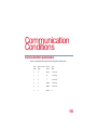
Appendix B: Communication Conditions................................ 66
Glossary..................................................................................... 69
Index........................................................................................... 80


xii
Introduction
Congratulations on becoming the owner of a V.90 56K compliant
internal modem offering advanced functions for fax and data
communication. This user’s guide provides detailed information
on features, operation and technical specifications of your internal
modem.
The V.90 56K internal modem provides capability for facsimile
transmissions and standard computer-to-computer data
communications.
The internal modem has a modem port (RJ11) for connecting to an
analog telephone line.
CAUTION: Connect the internal modem ONLY to an analog
line, not to a digital line. For more information, see
“Connection procedures” on page 5.
Due to FCC limitations, speeds of 53 kbps are the maximum
permissible transmission rates during downloads. Actual data
transmission speeds will vary depending on line conditions. Many
users will experience throughput in the range of 32 to 44 kbps
under normal conditions, depending on telephone line quality.

xiii
Some phone lines will not support V.90 56K connections at all,
either because of quality impairments or additional digital-to-
analog conversions (i.e., PBX systems). The modem uses the V.34
protocol for “upstream” data transmission, which supports
connection rates of up to 33,600 bits/second.
NOTE: 56K rates can be achieved only when one V.90 56K
modem communicates with a V.90 56K host modem (i.e., a
V.90 56K end-user client modem connects to a V.90 56K
ISP-site modem).
The Toshiba internal modem automatically selects the V.34
protocol if the remote modem lacks V.90 capabilities or if a
combination of network and/or phone line conditions prevent the
V.90 connection. In this case, the maximum connect rate will be
33,600 bits/second.
This section of the user’s guide describes features of the internal
modem.
Features
56K data
communication
The internal modem uses the V.90 protocol to connect
at data rates of up to 53,000 bits per second (bps) to
other modems employing the V.90 protocol. For
connection to non-V.90 modems, the internal modem
uses the ITU standard V.34 protocol to connect at
rates of up to 33,600 bits per second. The internal
modem also supports all of the earlier, lower-speed
ITU/CCITT modem protocols.
Fax capability You can use the internal modem to transmit and
receive facsimiles at rates of up to 14,400 bps. The
internal modem supports Class 1 fax transmission.
Refer to the function charts in this chapter.

xiv
Standard commands The internal modem is compatible with the industry
standard Hayes
®
AT commands and S-Register
settings.
Error control This feature assures accurate data transmission even
over telephone lines subject to noise interference. The
internal modem uses Microcom Networking
Protocol
®
4 (MNP
®
4) and V.42 error correction.
Data compression Compression can greatly increase data throughput.
The internal modem has MNP5 and V.42bis data
compression protocols.
Serial port access The internal modem frees your computer’s serial port
for connection of a serial mouse, serial printer or other
serial device.
Ring indicator The computer can be powered on automatically when
the modem answers a call. This feature is available
only when the computer is in Resume/Standby mode.
Refer to your computer’s documentation for details on
ring indicator power on.
Standby/Hibernate When the computer is set to Standby or Hibernate, the
modem settings automatically resume when you turn
on the power. Refer to your computer’s
documentation for details on Standby/Hibernate
modes.

xv
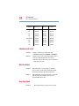
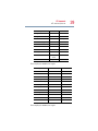
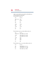
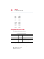
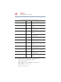
Function charts
The chart below lists the internal modem’s supported
communication protocols:
Functions available in all operating systems
Function Remarks
Data V.90 From 32 Kbps to 56 Kbps
V.34 From 2400 bps to 33.6 Kbps
V.32bis 4800, 7200, 9600 bps, 12, 14.4 Kbps
V.32 4800, 9600 bps
V.22bis 1200, 2400 bps
V.22 1200 bps
V.23 75, 600, 1200 bps
V.21 300 bps
BELL212A 1200 bps
BELL103 300 bps
MNP5 Data compression
MNP4 Error control
V.42bis Data compression
V.42 Error control
Fax V.17 7200, 9600 bps, 12, 14.4 Kbps
Note: bps stands for bits per second

xvi
User’s guide contents
This user’s guide is composed of six chapters, plus an
Introduction, two appendixes, a glossary, and an index.
❖ The Introduction describes the functions and capabilities of
the internal modem.
❖ Chapter 1, Setup, describes how to set up and configure the
internal modem and provides information on checking
modem functions.
❖ Chapter 2, Using the Internal Modem, describes basic
operations including connecting the modem and country
selection.
❖ Chapter 3, AT Commands, explains the meanings of the AT
commands that control your internal modem.
❖ Chapter 4, S-Registers, explains the meanings of the registers
that contain the settings for many of the internal modem
functions.
❖ Chapter 5, MNP and V.42, explains error correction, flow
control, and data compression.
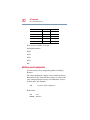
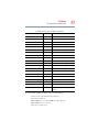
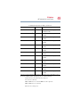
V.29 7200, 9600 bps
V.27ter 2400, 4800 bps
V.21 ch2 300 bps
EIA-578 Class 1 command set for fax
Functions available in all operating systems (Continued)
Function Remarks
Note: bps stands for bits per second

xvii
❖ Chapter 6, Test Function, describes how to conduct the
loopback test.
❖ The Appendixes provide technical information.
❖ The Glossary defines telecommunications terminology.
❖ The Index quickly directs you to information contained in the
user’s guide.
Conventions
This user’s guide uses the following formats to describe, identify,
and highlight terms and operating procedures.
Abbreviations
On first appearance, and whenever necessary for clarity,
abbreviations are enclosed in parentheses following their
definition. For example: Read Only Memory (ROM). Acronyms
are also defined in the Glossary.
Keys
The keyboard keys are used in the text to describe many computer
operations. A distinctive typeface identifies the key top symbols as
they appear on the keyboard. For example,
Enter identifies the
Enter key.
Key operation
Some operations require you to simultaneously use two or more
keys. We identify such operations by the key top symbols
separated by a plus sign (+). For example,
Ctrl + C means you must
hold down
Ctrl and at the same time press C. If three keys are used,
hold down the first two and at the same time press the third.

xviii
Display
Messages
Messages are used in this user’s guide to bring important
information to your attention. Each type of message is identified
as shown below.
CAUTION: Pay attention! A caution informs you that
improper use of equipment or failure to follow instructions
may cause data loss or damage your equipment.
NOTE: Please read. A note is a hint or advice that helps you
make best use of your equipment.
ATDT Text you are to type in is represented in the
type face you see to the left.
ABC Text generated by the computer that appears on its
display screen is presented in the type face you see to the
left (bold).


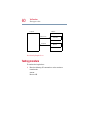
1
Setup
This chapter describes how to set up your hardware and how to
check the internal modem’s functions. It is written primarily for
users who, for some reason, need to set up the modem again.
Some procedures may vary slightly for users who have a
preinstalled modem.
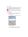
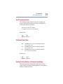
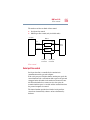
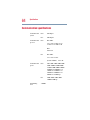
Hardware Setup
Use the MS-DOS
®
or TSETUP program to set the COM port, I/O
address port, and IRQ level. Refer to your computer’s
documentation.
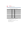
The default settings are:
Device Configuration All devices
Built-in Modem Com 2 (2F8H/IRQ3)
Page is loading ...
Page is loading ...
Page is loading ...
Page is loading ...
Page is loading ...
Page is loading ...
Page is loading ...
Page is loading ...
Page is loading ...
Page is loading ...
Page is loading ...
Page is loading ...
Page is loading ...
Page is loading ...
Page is loading ...
Page is loading ...
Page is loading ...
Page is loading ...
Page is loading ...
Page is loading ...
Page is loading ...
Page is loading ...
Page is loading ...
Page is loading ...
Page is loading ...
Page is loading ...
Page is loading ...
Page is loading ...
Page is loading ...
Page is loading ...
Page is loading ...
Page is loading ...
Page is loading ...
Page is loading ...
Page is loading ...
Page is loading ...
Page is loading ...
Page is loading ...
Page is loading ...
Page is loading ...
Page is loading ...
Page is loading ...
Page is loading ...
Page is loading ...
Page is loading ...
Page is loading ...
Page is loading ...
Page is loading ...
Page is loading ...
Page is loading ...
Page is loading ...
Page is loading ...
Page is loading ...
Page is loading ...
Page is loading ...
Page is loading ...
Page is loading ...
Page is loading ...
Page is loading ...
Page is loading ...
Page is loading ...
Page is loading ...
Page is loading ...
Page is loading ...
Page is loading ...
Page is loading ...
Page is loading ...
Page is loading ...
Page is loading ...
Page is loading ...
Page is loading ...
Page is loading ...
Page is loading ...
Page is loading ...
Page is loading ...
Page is loading ...
Page is loading ...
Page is loading ...
Page is loading ...
Page is loading ...
Page is loading ...
Page is loading ...
-
 1
1
-
 2
2
-
 3
3
-
 4
4
-
 5
5
-
 6
6
-
 7
7
-
 8
8
-
 9
9
-
 10
10
-
 11
11
-
 12
12
-
 13
13
-
 14
14
-
 15
15
-
 16
16
-
 17
17
-
 18
18
-
 19
19
-
 20
20
-
 21
21
-
 22
22
-
 23
23
-
 24
24
-
 25
25
-
 26
26
-
 27
27
-
 28
28
-
 29
29
-
 30
30
-
 31
31
-
 32
32
-
 33
33
-
 34
34
-
 35
35
-
 36
36
-
 37
37
-
 38
38
-
 39
39
-
 40
40
-
 41
41
-
 42
42
-
 43
43
-
 44
44
-
 45
45
-
 46
46
-
 47
47
-
 48
48
-
 49
49
-
 50
50
-
 51
51
-
 52
52
-
 53
53
-
 54
54
-
 55
55
-
 56
56
-
 57
57
-
 58
58
-
 59
59
-
 60
60
-
 61
61
-
 62
62
-
 63
63
-
 64
64
-
 65
65
-
 66
66
-
 67
67
-
 68
68
-
 69
69
-
 70
70
-
 71
71
-
 72
72
-
 73
73
-
 74
74
-
 75
75
-
 76
76
-
 77
77
-
 78
78
-
 79
79
-
 80
80
-
 81
81
-
 82
82
-
 83
83
-
 84
84
-
 85
85
-
 86
86
-
 87
87
-
 88
88
-
 89
89
-
 90
90
-
 91
91
-
 92
92
-
 93
93
-
 94
94
-
 95
95
-
 96
96
-
 97
97
-
 98
98
-
 99
99
-
 100
100
-
 101
101
-
 102
102


Ask a question and I''ll find the answer in the document
Finding information in a document is now easier with AI
Other documents
-
Abocom EFM560 User manual
-
 ATO V.9256K User manual
-
Abocom IFM560B User manual
-
Motorola ME-560M User manual
-
Acer FAX/Voice/Data Modem User manual
-
Trendnet TFM-560R Owner's manual
-
Multi-Tech Systems MT5634ZLX/FE User manual
-
MaxTech PCI Internal Voice/FAX/Data/Speakerphone Modem User manual
-
Multi-Tech MT5634ZPX Owner's manual
-
3com 005683-01 - User manual
