Weslo WLEX30480 User manual
- Type
- User manual

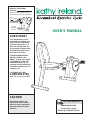
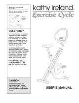
USER’S MANUAL
CAUTION
Read all precautions and
instructions in this manual
before using this equipment.
Keep this manual for future
reference.
Serial
Number
Decal
Model No. WLEX30480
Serial No.
Write the serial number in the
space above for future reference.
QUESTIONS?
As a manufacturer, we are
committed to providing com-
plete customer satisfaction.
If you have questions, or if
there are missing parts, we
will guarantee complete satis-
faction through direct assis-
tance from our factory.
TO AVOID UNNECESSARY
DELAYS, PLEASE CALL
DIRECT TO OUR TOLL-FREE
CUSTOMER HOT LINE. The
trained technicians on our
customer hot line will provide
immediate assistance, free of
charge to you.
CUSTOMER HOT LINE:
1-800-999-3756
Mon.–Fri., 6 a.m.–6 p.m. MST
Visit our website at
www.weslo.com
new products, prizes,
fitness tips, and much more!

2
TABLE OF CONTENTS
IMPORTANT PRECAUTIONS . . . . . . . . . . . . . . . . . . . . . . . . . . . . . . . . . . . . . . . . . . . . . . . . . . . . . . . . . . . . .2
BEFORE YOU BEGIN . . . . . . . . . . . . . . . . . . . . . . . . . . . . . . . . . . . . . . . . . . . . . . . . . . . . . . . . . . . . . . . . . . .3
PART IDENTIFICATION CHART . . . . . . . . . . . . . . . . . . . . . . . . . . . . . . . . . . . . . . . . . . . . . . . . . . . . . . . . . . .3
ASSEMBLY . . . . . . . . . . . . . . . . . . . . . . . . . . . . . . . . . . . . . . . . . . . . . . . . . . . . . . . . . . . . . . . . . . . . . . . . . . .4
HOW TO USE THE EXERCISE CYCLE . . . . . . . . . . . . . . . . . . . . . . . . . . . . . . . . . . . . . . . . . . . . . . . . . . . . . .6
STORAGE AND TROUBLE-SHOOTING . . . . . . . . . . . . . . . . . . . . . . . . . . . . . . . . . . . . . . . . . . . . . . . . . . . . .7
CONDITIONING GUIDELINES . . . . . . . . . . . . . . . . . . . . . . . . . . . . . . . . . . . . . . . . . . . . . . . . . . . . . . . . . . . . .9
PART LIST . . . . . . . . . . . . . . . . . . . . . . . . . . . . . . . . . . . . . . . . . . . . . . . . . . . . . . . . . . . . . . . . . . . . . . . . . . .10
EXPLODED DRAWING . . . . . . . . . . . . . . . . . . . . . . . . . . . . . . . . . . . . . . . . . . . . . . . . . . . . . . . . . . . . . . . . .11
HOW TO ORDER REPLACEMENT PARTS . . . . . . . . . . . . . . . . . . . . . . . . . . . . . . . . . . . . . . . . . . .Back Cover
LIMITED WARRANTY . . . . . . . . . . . . . . . . . . . . . . . . . . . . . . . . . . . . . . . . . . . . . . . . . . . . . . . . . . .Back Cover
IMPORTANT PRECAUTIONS
WARNING:
To reduce the risk of serious injury, read the following important precau-
tions before using the exercise cycle.
1. Read all instructions in this manual before
using the exercise cycle. Use the exercise
cycle only as described.
2. It is the responsibility of the owner to ensure
that all users of the exercise cycle are ade-
quately informed of all precautions.
3. Use the exercise cycle indoors, away from
moisture and dust. Place the exercise cycle
on a level surface, with a mat beneath it to
protect the floor or carpet from damage.
4. Inspect and tighten all parts regularly.
Replace any worn parts immediately.
5. Keep children under the age of 12 and pets
away from the exercise cycle at all times.
6. The exercise cycle should not be used by
persons weighing more than 250 pounds.
7. Wear appropriate clothing when exercising;
do not wear loose clothing that could become
caught on the exercise cycle. Always wear
athletic shoes for foot protection.
8. If you feel pain or dizziness at any time
while exercising, stop immediately and
begin cooling down.
9. Always keep your back straight when using
the exercise cycle. Do not arch your back.
10.The exercise cycle is intended for in-home
use only. Do not use the exercise cycle in a
commercial, rental, or institutional setting.
11. The exercise cycle does not have a free-
wheel; the pedals will continue to move until
the flywheel stops.
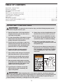
12.The decal shown below has been placed on
the exercise cycle. If the decal is missing, or
if it is not legible, call our toll-free Customer
Service Department to order a free replace-
ment decal.
WARNING:Before beginning this or any exercise program, consult your physician.
This is especially important for persons over the age of 35 or persons with pre-existing health prob-
lems. Read all instructions before using. ICON assumes no responsibility for personal injury or
property damage sustained by or through the use of this product.
Warning Decal is shown
at 80% of its actual size.

3
BEFORE YOU BEGIN
Thank you for selecting the new KATHY IRELAND™
RECUMBENT EXERCISE CYCLE. The KATHY IRE-
LAND™ exercise cycle blends advanced engineering
with contemporary styling to provide you with a low-
impact workout in the convenience and privacy of
your own home.
For your benefit, read this manual carefully before
you use the KATHY IRELAND™ RECUMBENT
EXERCISE CYCLE. If you have questions after
reading the manual, please call our Customer Service
Department toll-free at 1-800-999-3756, Monday
through Friday, 6 a.m. until 6 p.m. Mountain Time
(excluding holidays). To help us assist you, please
mention the product model number and serial number
when calling. The model number is WLEX30480. The
serial number can be found on a decal attached to the
exercise cycle (see the front cover of this manual for
the location of the decal).
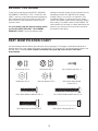
M6 Locknut (52)–6
M4 x 16mm Screw (46)—1
M8 Locknut (39)–4
M8 Lock Washer (57)–2
M6 Washer (35)–4
M8 x 36mm Hex Head Bolt (56)–2
M6 x 16mm Round Head
Screw (55)–8
M6 x 52mm Button Head Screw (47)–4M6 x 34mm Button Head Bolt (19)–4
M8 x 65mm Carriage Bolt (5)–4
PART IDENTIFICATION CHART
Use the drawings below to identify the small parts used in assembly. The number in parenthesis below each
drawing refers to the key number of the part, from the PART LIST on page 10. The second number refers to the
quantity used in assembly. Note: If a part is not found in the parts bag, check to see if it has been
preassembled.

Place all parts of the exercise cycle in a cleared area and remove the packing materials. Do not dispose of the
packing materials until assembly is completed. Assembly requires the included allen wrench ,
a phillips screwdriver , and two adjustable wrenches .
4
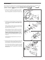
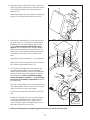
ASSEMBLY
1. Hold one of the Stabilizers (2) against the saddle on
the Frame (1). Attach the Stabilizer with two M8 x
65mm Carriage Bolts (5) and two M8 Locknuts (39).
1
39
1
5
2
2. Slide the Seat Frame Bushing (17) onto the Frame
(1) as shown. Next, insert the Frame Bushing (18)
into the Frame (1) and attach it with an M4 x 16mm
Screw (46).
Refer to drawing 2a. Move the Seat Frame Bushing
(17) until the tabs (A) are positioned over the rectan-
gular slots (B) in the Frame (1).
Refer to drawing 2. Press the tabs (A) on the Seat
Frame Bushing (17) with your thumb and index fin-
ger, and carefully slide the Seat Frame (3) onto the
Frame (1) and the Seat Frame Bushing (17); be
careful to avoid pinching your fingers. Make sure
that the tabs (A) snap into the holes (C) in the Seat
Frame (3).
Finally, tighten the Adjustment Knob (16) into the
Seat Frame (3).
3. Attach the Lower Seat Frame (58) to the Seat Frame
(3) with four M6 x 52mm Button Head Screws (47),
four M6 Washers (35), and four M6 Locknuts (52).
Next, hold the other Stabilizer (2) against the saddle
on the Lower Seat Frame (58). Attach the Stabilizer
with two M8 x 65mm Carriage Bolts (5) and two M8
Locknuts (39).
3
5
35
47
58
39
3
52
35
52
2
2
46
1
A
C
16
17
3
18
2a
A
B
17
1

5
4
5
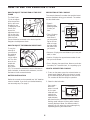
4. Slide the Backrest Frame (20) into the Lower Seat
Frame (58). Attach the Backrest Frame with two M8
x 36mm Hex Head Bolts (56) and two M8 Lock
Washers (57).
Attach the Backrest (21) to the Backrest Frame (20)
with four M6 x 16mm Round Head Screws (55).
5. Slide one of the Handlebars (6) onto the left side of
the Seat Frame (3). Insert two M6 x 34mm Button
Head Bolts (19) into the Handlebar and the Seat
Frame. Make sure that the Handlebar angles
upward. If the Handlebar does not angle upward,
slide the other Handlebar onto the left side of the
Seat Frame. If the Handlebar angles upward, tight-
en two M6 Locknuts (52) onto the Button Head
Bolts.
Assemble the other Handlebar (7) in the same way.
Attach the Seat (54) to the Seat Frame (3) with four
M6 x 16mm Round Head Screws (55).
21
20
57
55
56
58
19
6
52
54
7
55
3
55
48
Console
Plate
Console
Wire
8
22
9
49
6
6. The Console (48) requires two “AA” batteries (not
included). Alkaline batteries are recommended.
Refer to the inset drawing. Remove the battery door
from the Console. Press two batteries into the bat-
tery compartment. Make sure that the negative
ends of the batteries (marked “—”) are touching
the springs in the battery compartment. Reattach
the battery door.
Slide the Console (48) onto the console plate. Make
sure that the plastic clip on the back of the Console
snaps onto the tab on the console plate.
Connect the console wire to the Reed Switch Wire
(49).
Identify the Left Pedal (8), which is marked with an
“L.” Using an adjustable wrench, tighten the Left
Pedal counterclockwise into the left arm of the
Crank (22). Next, tighten the Right Pedal (9) clock-
wise into the right arm on the Crank.
7. Make sure that all parts are properly tightened before you use the exercise cycle.
Battery Door
Batteries
48

6
HOW TO USE THE EXERCISE CYCLE
HOW TO ADJUST THE POSITION OF THE SEAT
FRAME
The Seat Frame
(3) can be adjust-
ed to the position
that is most com-
fortable for you.
To adjust the Seat
Frame, first
loosen the
Adjustment Knob
(16) on the right
side of the frame.
Slide the Seat
Frame forward or backward to the desired position.
Retighten the Adjustment Knob.
HOW TO ADJUST THE PEDALING RESISTANCE
To vary the
intensity of
your exercise,
the pedaling
resistance
can be adjust-
ed. The resis-
tance is con-
trolled with
the Resis-
tance Knob
(27). To increase the resistance, turn the Resistance
Knob clockwise; to decrease the resistance, turn the
Resistance Knob counterclockwise.
BATTERY INSTALLATION
Before the console can be operated, two “AA” batteries
must be installed. If you have not installed batteries,
see assembly step 6 on page 5.
DESCRIPTION OF THE CONSOLE
The console features five modes that provide instant
exercise feedback during your workouts. The modes
are described below.
• Speed—
Displays your
pedaling speed,
in miles per
hour.
• Time—Displays
the elapsed
time. Note: If
you stop pedal-
ing for ten sec-
onds or longer,
the time mode
will pause until
you resume.
• Distance—Displays the total distance you have ped-
aled, in miles.
• Calorie—Displays the approximate number of calo-
ries you have burned.
• Scan—Displays the speed, time, distance, and calo-
rie modes, for 5 seconds each, in a repeating cycle.
HOW TO OPERATE THE CONSOLE
1. To turn on the power, press the on/reset button or
simply begin pedaling. When the power is turned
on, the entire display will appear for two seconds.
The console will then be ready for operation.
2. Select the desired mode:
Scan mode—
When the
power is turned
on, the scan
mode will auto-
matically be
selected. One
mode indicator
will show that the scan mode is selected, and a
flashing mode indicator will show which mode is
currently displayed. Note: If a different mode is
selected, you can select the scan mode again by
repeatedly pressing the mode button.
3
16
Mode Indicators
Display
27

7
Speed, time,
distance or
calorie
mode—To
select one of
these modes
for continuous
display, press
the mode button repeatedly. The mode indicators
will show which mode is selected. Make sure that
the scan mode is not selected.
3. To reset the display, press the on/reset button.
4. To turn off the power, simply wait for about four min-
utes. Note: The monitor has an “auto-off” fea-
ture. If the pedals are not moved and the moni-
tor buttons are not pressed for four minutes,
the power will turn off automatically in order to
conserve the batteries.
Inspect and tighten all parts of the exercise cycle
regularly. Replace any worn parts immediately.
The exercise cycle can be cleaned with a soft, damp
cloth. Avoid spilling liquid on the console. Keep the
console out of direct sunlight or the display may be
damaged. Remove the batteries when storing the
exercise cycle.
BATTERY REPLACEMENT
If the console does not function properly, the batteries
should be replaced. See assembly step 6 on page 5.
In addition, make sure that the console wire is con-
nected to the reed switch wire.
HOW TO STORE THE EXERCISE CYCLE
When the exercise
cycle is not in use,
it can be adjusted
to the storage posi-
tion. Refer to the
drawing at the
right. Loosen the
Adjustment Knob
(16) on the right
side of the Seat
Frame (3). Slide
the Frame (1) as
far into the Seat Frame as it will go. Tighten the
Adjustment Knob. Store the exercise cycle indoors,
away from moisture and dust.
STORAGE AND TROUBLE-SHOOTING
16
3
1
NOTE: Your console displays speed in either miles per hour (mph) or revolutions per minute (rpm). If the
displayed speed has a decimal point, your console displays speed in miles per hour; if the displayed speed does
not have a decimal point, your console displays speed in revolutions per minute. Use the chart below to convert
one unit of measurement to the other, if desired
If your console displays speed in miles per hour, it displays distance in miles. If your console displays speed in
revolutions per minute, it displays distance in total revolutions (revs). Use the chart below to convert one unit of
measurement to the other, if desired.

8
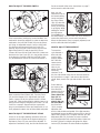
HOW TO ADJUST THE REED SWITCH
If the console does not display correct feedback, the
reed switch should be adjusted. In order to adjust the
reed switch, the Left Side Shield (10) must be remov-
ed. Using an adjustable wrench, turn the Left Pedal
(8) clockwise and remove it from the Crank (22).
Remove the three Side Shield Screws (40) from the
Right Side Shield (11) and the two M4 x 16mm
Screws (46) from the Left Side Shield (10). Make sure
that the arm of the Crank (22) is in the position shown
in the drawing. Carefully slide the Left Side Shield
(11) forward off the arm of the Crank and remove it.
Next, locate the Reed Switch (49). Turn the Crank
(22) until the Magnet (4) is aligned with the Reed
Switch. Loosen but do not remove the M4 x 16mm
Screw (46). Slide the Reed Switch slightly closer to or
away from the Magnet. Retighten the Screw. Turn the
Crank for a moment. Repeat until the console dis-
plays correct feedback. When the Reed Switch is cor-
rectly adjusted, reattach the left side shield and pedal.
HOW TO ADJUST THE RESISTANCE STRAP
If there is not enough pedaling resistance when the
resistance knob is turned to the highest setting, the
Resistance Strap (15) may need to be adjusted. To
adjust the Resistance Strap, the left side shield must
first be removed. Refer to the instructions on page 7
and remove the left side shield.
Next, turn the
resistance knob to
the lowest setting.
Locate and open
the Strap Clamp
(38). Grip the end
of the Resistance
Strap (15) and pull
it up slightly. While
holding the end of
the Resistance
Strap, fully close
the Strap Clamp. Turn the Crank (22) for a moment to
make sure that there is not too much resistance.
When the Resistance Strap is properly adjusted, reat-
tach the left side shield and pedal.
HOW TO ADJUST THE DRIVE BELT
The exercise
cycle features a
drive belt that
must be kept
properly adjust-
ed. If the belt
causes exces-
sive noise or
slips as you
pedal, the belt
should be
checked. To do
this, the side shields must first be removed. Refer to
the instructions on page 7 and remove the left side
shield. Next, remove the right side shield in the same
way.
Press down on
the center of the
Drive Belt (14)
between the front
and rear pulleys.
There should be
from 1/4” to
1/2” of move-
ment in the cen-
ter of the Belt. If
the Drive Belt
(14) is properly
adjusted, reat-
tach the side shields and pedals. If the Belt needs to
be adjusted, loosen the Nylon Locknut (36) on the left
side of the Flywheel (29). To tighten the Belt, turn the
Adjustment Bolt (31) clockwise; to loosen the Belt,
turn the Adjustment Bolt counterclockwise. Make sure
that the Flywheel is straight and tighten the Nylon
Locknut (36). Reattach the side shields and pedals.
22
29
14
Top View
Top View
14
36
31
38
15
10
22
11
46
8
40
40
22
49
46
4

9
CONDITIONING GUIDELINES
The following guidelines will help you to plan your
exercise program. Remember that proper nutrition
and adequate rest are essential for successful results.
EXERCISE INTENSITY
Whether your goal is to burn fat or to strengthen your
cardiovascular system, the key to achieving the
desired results is to exercise with the proper intensity.
The proper intensity level can be found by using your
heart rate as a guide. The chart below shows recom-
mended heart rates for fat burning, maximum fat
burning, and cardiovascular (aerobic) exercise.
To find the proper heart rate for you, first find your age
on either side of the chart (ages are rounded off to the
nearest ten years). Next, find the three numbers to
the side of your age. The three numbers are your
“training zone.” The lowest number is the recommend-
ed heart rate for fat burning; the middle number is the
heart rate for maximum fat burning; the highest
number is the heart rate for aerobic exercise.
Burning Fat
To burn fat effectively, you must exercise at a rela-
tively low intensity level for a sustained period of time.
During the first few minutes of exercise, your body
uses easily accessible carbohydrate calories for ener-
gy. Only after the first few minutes of exercise does
your body begin to use stored fat calories for energy.
If your goal is to burn fat, adjust the intensity of your
exercise until your heart rate is near the lowest num-
ber in your training zone as you exercise.
For maximum fat burning, adjust the intensity of your
exercise until your heart rate is near the middle num-
ber in your training zone as you exercise.
Aerobic Exercise
If your goal is to strengthen your cardiovascular sys-
tem, your exercise must be “aerobic.” Aerobic exer-
cise is activity that requires large amounts of oxygen
for prolonged periods of time. This increases the
demand on the heart to pump blood to the muscles,
and on the lungs to oxygenate the blood. For aerobic
exercise, adjust the intensity of your exercise until
your heart rate is near the highest number in your
training zone.
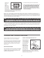
HOW TO MEASURE YOUR HEART RATE
To measure your
heart rate, first exer-
cise for at least four
minutes. Then, stop
exercising and place
two fingers on your
wrist as shown. Take
a six-second heart-
beat count, and mul-
tiply the result by 10
to find your heart rate. For example, if your six-second
heartbeat count is 14, your heart rate is 140 beats per
minute. (A six-second count is used because your
heart rate will drop rapidly when you stop exercising.)
WORKOUT GUIDELINES
Each workout should include the following three parts:
A warm-up, consisting of 5 to 10 minutes of stretch-
ing and light exercise. A proper warm-up increases
your body temperature, heart rate, and circulation in
preparation for exercise.
Training zone exercise, consisting of 20 to 30 min-
utes of exercising with your heart rate in your training
zone. (During the first few weeks of your exercise pro-
gram, do not keep your heart rate in your training
zone for longer than 20 minutes.)
WARNING:Before beginning this
or any exercise program, consult your physi-
cian. This is especially important for persons
over the age of 35 or persons with pre-exist-
ing health problems.

10
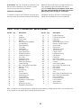
PART LIST—Model No. WLEX30480 R0400A
Note: “#” refers to a non-illustrated part. Specifications are subject to change without notice. See the back cover
of this manual for information about ordering replacement parts.
Key No. Qty. Description Key No. Qty. Description
A cool-down, with 5 to 10 minutes of stretching. This
will increase the flexibility of your muscles and will
help to prevent post-exercise problems.
EXERCISE FREQUENCY
To maintain or improve your condition, plan three work-
outs each week, with at least one day of rest between
workouts. After a few months of regular exercise, you
may complete up to five workouts each week, if
desired. Caution: Be sure to progress at your own
pace and avoid overdoing it. Incorrect or excessive
training may result in injury to your health.
Remember, the key to success is make exercise a
regular and enjoyable part of your everyday life.
1 1 Frame
2 2 Stabilizer
3 1 Seat Frame
4 1 Magnet
5 4 M8 x 65mm Carriage Bolt
6 1 Left Handlebar
7 1 Right Handlebar
8 1 Left Pedal
9 1 Right Pedal
10 1 Left Side Shield
11 1 Right Side Shield
12 2 Handlebar Endcap
13 4 Stabilizer Endcap
14 1 Drive Belt
15 1 Resistance Strap
16 1 Adjustment Knob
17 1 Seat Frame Bushing
18 1 Frame Bushing
19 4 M6 x 34mm Button Head Bolt
20 1 Backrest Frame
21 1 Backrest
22 1 Crank/Pulley
23 1 Roll Pin
24 1 Crank Washer
25 2 Half Bushing Set
26 2 Crank Bushing
27 1 Resistance Knob
28 1 Resistance Control/Cable
29 1 Flywheel
30 1 M10 Nylon Locknut
31 1 Adjustment Sleeve/Bolt
32 2 Flywheel Bushing
33 1 Flywheel Pulley/Axle
34 2 Foam Grip
35 4 M6 Washer
36 1 1/2-13 UNC Nylon Locknut
37 1 Backrest Frame Endcap
38 1 Strap Clamp
39 4 M8 Locknut
40 3 Side Shield Screw
41 1 Tension Spring
42 1 Clamp Screw
43 1 Resistance Spring
44 4 1/4” Washer
45 1 Clamp Nut
46 6 M4 x 16mm Screw
47 4 M6 x 52mm Button Head Screw
48 1 Console
49 1 Reed Switch w/Wire
50 1 M4 x 16mm Flat Head Screw
51 1 M10 Washer
52 6 M6 Locknut
53 1 Reed Switch Clamp
54 1 Seat
55 8 M6 x 16mm Round Head Screw
56 2 M8 x 36mm Hex Head Bolt
57 2 M8 Lock Washer
58 1 Lower Seat Frame
# 1 User’s Manual
# 1 Allen Wrench
# 1 Assembly Tool

11
47
55
20
17
16
6
12
19
27
28
39
7
18
46
34
37
11
15
14
39
39
48
3
49
10
52
54
52
46
40
46
45
44
42
43
41
33
32
31
30
29
51
36
22
4
26
25
24
23
22
25
53
46
5
2
13
13
5
2
13
13
9
8
1
38
50
21
12
19
52
55
34
35
56
57
58
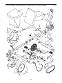
EXPLODED DRAWING—Model No. WLEX30480 R0400A

Part No. 149267 R0400A Printed in China © 2000 ICON Health & Fitness, Inc.
HOW TO ORDER REPLACEMENT PARTS
To order replacement parts, call our Customer Service Department toll-free at 1-800-999-3756, Monday through
Friday, 6 a.m. until 6 p.m. Mountain Time (excluding holidays). To help us assist you, please be prepared to give
the following information:
• The MODEL NUMBER of the product (WLEX30480).
• The NAME of the product (KATHY IRELAND™ RECUMBENT EXERCISE CYCLE).
• The SERIAL NUMBER of the product (see the front cover of this manual).
• The KEY NUMBER and DESCRIPTION of the part(s) (see the PART LIST on page 10 of this manual).
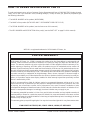
LIMITED WARRANTY
ICON Health & Fitness, Inc. (ICON), warrants this product to be free from defects in workmanship and
material, under normal use and service conditions, for a period of ninety (90) days from the date of pur-
chase. This warranty extends only to the original purchaser. ICON's obligation under this warranty is lim-
ited to replacing or repairing, at ICON's option, the product at one of its authorized service centers. All
products for which warranty claim is made must be received by ICON at one of its authorized service cen-
ters with all freight and other transportation charges prepaid, accompanied by sufficient proof of purchase.
All returns must be pre-authorized by ICON. This warranty does not extend to any product or damage to
a product caused by or attributable to freight damage, abuse, misuse, improper or abnormal usage or
repairs not provided by an ICON authorized service center, to products used for commercial or rental pur-
poses, or to products used as store display models. No other warranty beyond that specifically set forth
above is authorized by ICON.
ICON is not responsible or liable for indirect, special or consequential damages arising out of or in con-
nection with the use or performance of the product or damages with respect to any economic loss, loss
of property, loss of revenues or profits, loss of enjoyment or use, costs of removal, installation or other
consequential damages of whatsoever nature. Some states do not allow the exclusion or limitation of inci-
dental or consequential damages. Accordingly, the above limitation may not apply to you.
The warranty extended hereunder is in lieu of any and all other warranties and any implied warranties of
merchantability or fitness for a particular purpose is limited in its scope and duration to the terms set forth
herein. Some states do not allow limitations on how long an implied warranty lasts. Accordingly, the above
limitation may not apply to you.
This warranty gives you specific legal rights. You may also have other rights which vary from state to state.
ICON HEALTH & FITNESS, INC., 1500 S. 1000 W., LOGAN, UT 84321-9813
WESLO is a registered trademark of ICON Health & Fitness, Inc.
-
 1
1
-
 2
2
-
 3
3
-
 4
4
-
 5
5
-
 6
6
-
 7
7
-
 8
8
-
 9
9
-
 10
10
-
 11
11
-
 12
12


Weslo WLEX30480 User manual
- Type
- User manual
Ask a question and I''ll find the answer in the document
Finding information in a document is now easier with AI
Related papers
-
Weslo WLEX27180 User manual
-
-
-
-
-
-
-
-
-
Other documents
-
 Kathy Ireland Home WLEX30380 User manual
-
ProForm VR 900 EKG User manual
-
-
Sears 831.288720 User manual
-
NordicTrack Sl730 Bike User manual
-
-
HealthRider N35 HREX2076.0 User manual
-
-
-
ProForm Pro-Form C55 User manual
