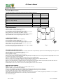
Billy Goat CR550HC is a powerful and versatile machine designed for removing thatch from your lawn, renovation of existing lawns, and to assist in overseeding operations. The slicing reel can be used in grasses that require vertical cutting and assists in lawn overseeding projects. The flail blades can be replaced with the slicing reel for different needs. The spacer bumpers help to maintain mowing height and prevent scalping.
Billy Goat CR550HC is a powerful and versatile machine designed for removing thatch from your lawn, renovation of existing lawns, and to assist in overseeding operations. The slicing reel can be used in grasses that require vertical cutting and assists in lawn overseeding projects. The flail blades can be replaced with the slicing reel for different needs. The spacer bumpers help to maintain mowing height and prevent scalping.


-
 1
1
-
 2
2
-
 3
3
-
 4
4
-
 5
5
-
 6
6
-
 7
7
-
 8
8
-
 9
9
-
 10
10
-
 11
11
-
 12
12
-
 13
13
-
 14
14
-
 15
15
-
 16
16


Billy Goat CR550HC is a powerful and versatile machine designed for removing thatch from your lawn, renovation of existing lawns, and to assist in overseeding operations. The slicing reel can be used in grasses that require vertical cutting and assists in lawn overseeding projects. The flail blades can be replaced with the slicing reel for different needs. The spacer bumpers help to maintain mowing height and prevent scalping.
Ask a question and I''ll find the answer in the document
Finding information in a document is now easier with AI
Related papers
-
Billy Goat CR550HCV User manual
-
-
-
Simplicity POWER RAKE, BILLY GOAT User manual
-
Billy Goat PR550T User manual
-
-
-
-
-
Other documents
-
Simplicity VANGUARD COMPACT POWER RAKE User manual
-
Encore Power Thatch RSA20N-BS50 Owner's manual
-
 Backyard X-Scapes 511-60XL Installation guide
-
 Redexim Verti-Drain 7007 Hydro User manual
-
Flymo 5011759025270 Datasheet
-
Bluebird PR22H5NRA 968 99 94-29 Owner's manual
-
Toro 205 Turf Seeder User manual
-
Husqvarna DT22 User manual
-
Husqvarna 966067001 User manual
-
 Redexim Verti-Drain® 7007 Owner's manual


