Page is loading ...

Ayre P-5xe
Owner’s Manual
MC/MM Phono Preamplifier


Table of
Contents
Welcome to Ayre . . . . . . . . . . . . . . . . . . . . . . . 2
Connections and Installation . . . . . . . . . . . . . . . . . . . . 3
Controls and Operation. . . . . . . . . . . . . . . . . . . . . 6
Optimization and Customization . . . . . . . . . . . . . . . . . . 9
Numbers and Specifications . . . . . . . . . . . . . . . . . . 15
Statement of Warranty . . . . . . . . . . . . . . . . . . . . 16
A Place for Notes . . . . . . . . . . . . . . . . . . . . . . 19

Welcome to
Ayre
Your Ayre P-5xe offers a significant advance in the
musical performance of high-fidelity equipment.
The warmth and immediacy of a live performance
are apparent from the first listening. The
combination of superb resolution and a natural,
relaxed quality will draw you into the music, time
and time again.
This level of performance has been implemented
using the highest level of workmanship and
materials. You can be assured that the Ayre P-5xe
will provide you a lifetime of musical enjoyment.
To our North American customers, please be
sure to mail your warranty registration card and
photocopy of your original sales receipt within 30
days in order to extend the warranty to five
years.
2

Connections and
Installation
The Ayre P-5xe is easy to connect and use. The
following guidelines will ensure that the installation
goes smoothly.
Location
A good location for your phono preamplifier is in a
cabinet or on a shelf. Please note that the high-gain
circuitry required to amplify the low-level signal
from a phono cartridge may be sensitive to the
magnetic fields from transformers in other
equipment.
It is recommended to maintain a distance of 10"
to 20" (25 cm to 50 cm) to other components to
minimize hum levels.
Inputs
The balanced configuration
yields maximum sonic
performance with minimum
noise and hum.
As the phono cartridge is an inherently balanced
device, the Ayre P-5xe offers balanced inputs via
XLR connectors. Since most tone arms and/or
turntables are not currently equipped with XLR
3

connectors, there are two choices for making the
proper connection:
1) Use custom phono cables with XLR connectors at
the phono preamplifier end and the appropriate
connector (RCA or DIN, depending on the
particular installation) at the turntable end. This is
the preferred solution and offers the highest level of
sound quality, or;
2) Use the existing cables with RCA connectors to
connect to the unbalanced inputs of the P-5xe.
Custom phono cables with XLR connectors for
balanced operation are available from your local
Ayre dealer.
A small toggle switch near the input connectors
configures the circuit for either the balanced or
unbalanced inputs.
Only one set of inputs (balanced or
unbalanced) may be connected at a
time.
4
Input
Output
Input
Output
P-5x Phono Preamplifier
A y r e
Boulder, Colorado USA
S.N.
Volts
50/60 Hertz
10 W Max
UnbalUnbal
47k
100
1000
47k
1000
100
Gain Settings Inside
BalBal

Outputs
The Ayre P-5xe offers one pair of balanced (XLR)
outputs and one pair of unbalanced (RCA) outputs.
Although both sets of outputs are always active
regardless of which input (balanced or unbalanced)
is used, it is normally recommended to only use one
set of outputs at a time.
Note that the level of the unbalanced outputs will
be 6 dB lower than the balanced outputs.
AC Power
The phono preamplifier draws
only a small amount of power
and is designed to be left on at
all times.
Connect the Ayre P-5xe to an unswitched AC power
source. The front panel LED will glow blue to
indicate that the unit is powered. Although
proprietary RFI (radio-frequency interference)
filtering is built into the CD player, in some
situations an AC power-line filter (such as those
offered by Ayre) may provide additional sonic
benefits.
5

Controls and
Operation
The Ayre P-5xe offers the ultimate in flexibility and
performance for all types of phono cartridges.
Low-noise FET circuitry provides ultra-quiet
operation even with the lowest output cartridges.
Both gain and loading are easily adjustable to
accommodate both moving coil and moving magnet
designs.
Setting the Gain
Ayre’s exclusive zero-feedback design allows for a
wide range of signal gain, without the need for
step-up transformers or extra gain stages. Changing
the gain is easily accomplished with jumper blocks
inside the unit.
Disconnect the AC power before
removing the cover of the unit.
To access the gain adjustments, remove the 10
screws on the top cover using a 5/64" (2 mm) hex
wrench.
6

Suggested gain settings are:
Cartridge Gain Gain to Out
Output
Setting Bal/Unbal
> 3 mV Low 50/44 dB
1 – 3 mV Med* 60/54 dB
< 1 mV High 70/64 dB
These settings are guidelines only, and variations are
perfectly acceptable. Note that the gain does not
depend on which input is selected (balanced or
unbalanced), but only on which output is connected.
*Factory default setting.
7

Setting the Loading
Cartridge loading can be adjusted with switches on
the rear panel. The loading options built in to the
Ayre P-5xe are 47 kΩ, 1000 Ω, and 100 Ω. There is
a bank of two switches for each channel. When both
switches are in the “Up” position the cartridge load
is 47 kΩ, which is suitable for almost all cartridges.
It is recommended that the
loading not be changed from
47 k
when using a
moving-magnet cartridge.
Some moving-coil cartridges will yield better sonic
performance if they are loaded with a lower
impedance. Usually, a lower load impedance results
in a more focused soundstage, with greater image
solidity and less apparent distortion. A higher load
impedance will give a more open sound, with
greater air and life. The final loading value must be
chosen by ear to give the best sound in your
particular system.
Break-In
100 to 500 hours of music
played through the system will
ensure full break-in.
Due to the manufacturing processes used for the
circuit board and capacitors, a break-in period is
necessary for the phono preamplifier to reach its full
performance potential.
8

Optimization and
Customization
Technically oriented users may wish to explore
additional customization options that are available.
Custom Loading Resistors
When using custom loading
resistors, leave the loading
switches in the “Up” position
(47 kΩ).
Should additional loading values be desired, custom
loading resistors are also easily accommodated. As
there are two types of inputs (balanced and
unbalanced), simply connect the desired value of
loading resistor to the unused inputs using an
appropriate connector (RCA or XLR).
Required materials include a pair of high-quality
resistors of the desired value and an additional pair
of the appropriate connectors (RCA or XLR). Male
polarity connectors are required for the custom
loading resistors.
When using a balanced (XLR) connection to the
turntable, solder the desired value loading resistors
between the center pin and the shell of the
additional male RCA connectors. These additional
connectors are then inserted into the otherwise
unused unbalanced inputs of the P-5xe.
9

When using an unbalanced (RCA) connection to the
turntable, solder the custom loading resistors
between pins 2 and 3 of the additional male XLR
connectors. These additional connectors are then
inserted into the otherwise unused balanced inputs
of the P-5xe.
Custom Phono Cables
As noted in the “Connections and Installation”
section, a balanced connection from turntable to
phono preamplifier will provide the highest level of
performance. While Ayre offers pre-made cables of
the correct configuration, some users will prefer to
have custom phono cables made by another
manufacturer, or to modify their existing cables.
This section gives details on how to achieve the
proper connection.
In general, there will be a total of five connections to
the turntable:
• Left positive
• Left negative
• Right positive
• Right negative
• Tonearm and/or turntable ground
These should be connected to the phono
preamplifier using only a single ground connection,
in order to eliminate hum-inducing ground loops.
10

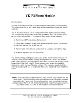
Turntables with RCA Connectors
One common turntable configuration has two RCA
jacks plus a ground post. Following is a schematic
diagram of a suitable custom cable:
This configuration has two separate cables plus a
ground wire, and requires balanced cabling with at
least two conductors plus a shield. If the cabling has
a third conductor (in addition to the shield), it
should be connected to pin 1 of the XLR connector
and left unconnected at the RCA end. If the cabling
has four or more conductors, they should be
paralleled to create two composite conductors.
Normally this turntable configuration has the RCA
connectors mounted to an unsuspended part of the
turntable and the cable’s stiffness will not interfere
with the turntable’s suspension. Should the RCA
connectors be mounted to a suspended part of the
11
1
1
Male RCA Shield
Male XLR
To
Turntable
To Phono
Preamplifier
Ground Wire
Spade Lug Spade Lug

turntable, the custom cables must be made flexible
to allow proper motion of the suspended sub-chassis.
This is normally done by removing a section of the
cable’s outer jacket near the turntable.
A custom phono cable using a single cable may also
be used as shown below:
Please note that this configuration requires cabling
that has a multiple of four conductors plus a shield.
If there are eight or twelve conductors, they must be
paralleled to create four composite conductors. Also,
a short section of the cable jacket must be removed
at each end of the custom cable to allow the
connectors to be physically separated.
Tonearms with a Mini-DIN Connector
Another common tonearm configuration has a 5-pin
mini-DIN connector below the turntable base. This
12
1
1
Shield
Male XLR
To
Turntable
To Phono
Preamplifier
Ground Wire
Spade LugSpade Lug
Male RCA

mini-DIN connector is nearly always on a suspended
part of the turntable, and care must be taken to
provide a flexible section of the custom phono cable
so that the turntable’s suspension can have free
motion.
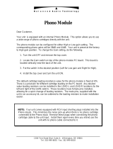
It is usually easier to create the required flexibility
by using a single cable with four conductors plus a
shield, instead of using a separate cable for each
channel. Below is the schematic diagram for a
suitable custom phono cable in this application,
with the DIN connector shown from the rear
(solder) side:
Remember that a section of the cable’s outer jacket
must be removed from each end of the custom cable.
This provides a flexible section at the tonearm end,
and allows the XLR connectors to be physically
separated at the phono preamplifier end.
13
To
Turntable
To Phono
Preamplifier
Female DIN
1
1
Shield
Male XLR
Ground Wire
Spade Lug

In the event that a four conductor cable is not
available, a pair of cables with at least two
conductors each may be used as shown in the
following diagram, with the DIN connector shown
from the rear (solder) side:
In this situation extra care must be taken to provide
a flexible section to avoid interference with the
turntable’s suspension. If the cabling has three
conductors (in addition to the shield), the third
conductor should be connected to pin 1 of the XLR
connectors and left unconnected at the tonearm end.
14
1
1
Shield
Male XLR
To
Turntable
To Phono
Preamplifier
Ground Wire
Spade Lug
Female DIN

Numbers and
Specifications
Input Impedance 47 kΩ, 1000 Ω , 100 Ω
(adjustable)
Gain 50 dB, 60 dB, 70 dB – balanced outputs
44 dB, 54 dB, 64 dB – unbalanced outputs
(adjustable)
Frequency Response RIAA Curve ± 0.05 dB
(20 Hz – 20 kHz)
Output Impedance 110 Ω– balanced outputs (55 Ωper phase)
55 Ω– unbalanced outputs
XLR Input Polarity Pin 1 – Ground
Pin 2 – Non-inverting (Positive)
Pin 3 – Inverting (Negative)
Power Consumption 10 watts
Dimensions 17-¼" W x 13-¾" D x 2-¾" H
44 cm x 35 cm x 7 cm
Weight 12 pounds
5.5 kg
15

Statement of
Warranty
North American Warranty
Your Ayre P-5xe phono preamplifier is warranted
against defects in workmanship and materials for a
period of ninety days from the date of original
purchase. This ninety-day coverage is automatic
upon acceptance of delivery and no registration is
required.
Additionally you have the option, at no cost, to
extend the warranty for a period of five years from
the date of purchase by returning the completed
Warranty Registration Card and a photocopy of
your original purchase receipt in the enclosed
postage-paid envelope to Ayre within thirty days of
product delivery. This optional warranty is only
available within the thirty-day registration period.
16

North American Warranty Statement
1. If any defects are found in the materials or
workmanship of this Ayre product within the
warranty period, the unit will be repaired or
replaced by Ayre Acoustics, Inc. (Ayre) or its
authorized agent.
2. Purchaser must return the product, packed in the
original shipping carton, freight prepaid to:
Ayre Acoustics, Inc.
2300-B Central Avenue
Boulder, Colorado 80301
or to Ayre’s authorized agent. The product must be
accompanied by a written description of the defect
and a photocopy of your original purchase receipt.
Ayre will not be responsible for any shipping
damage and strongly recommends the purchase of
shipping insurance.
3. Ayre reserves the right to inspect any product
that is the subject of any warranty claim prior to
repairing or replacing it. Final determination of
warranty coverage lies solely with Ayre.
Out-of-warranty claims will be billed for labor,
materials, return freight, and insurance as required.
Any product for which a warranty claim is accepted
will be returned to the purchaser and the cost of
shipping and insurance will be factory prepaid
within the boundaries of the USA. Units to be
shipped outside of the USA will be shipped freight
collect only.
17

4. Ayre strives to manufacture the finest possible
equipment, and therefore reserves the right to make
improvements on its products, without necessarily
assuming any obligation to retrofit such changes
upon its previously manufactured models.
5. The above warranty is the sole warranty given by
Ayre, and is in lieu of all other warranties. All
implied warranties, including warranties of
merchantability or fitness for any particular purpose
shall be strictly limited to the duration of the above
warranty. Ayre shall have no further obligation of
any kind, whether express or implied. Further, Ayre
shall in no event be obligated for any incidental or
consequential damages as a result of any defect or
any warranty claim, whether express or implied.
6. Ayre does not authorize any third party,
including any dealer or sales representative, to
assume any liability of Ayre or make any warranty
for Ayre. The unit must not have been altered or
improperly serviced. The serial number on the unit
must not have been altered or removed.
7. The remaining period of this warranty is only
transferable to subsequent purchasers if the product
is resold by an authorized Ayre dealer.
International Warranty
Warranty terms outside of North America may vary.
Please contact the authorized Ayre distributor in
your country of purchase for the terms of warranty
and also the service itself.
18
/